manuals.online logo
Brands
  1. Home
  2. •
  3. Brands
  4. •
  5. turck
  6. •
  7. Amplifier
  8. •
  9. turck interface modul IME-TI-11Ex-Ci/24VDC Operating and maintenance instructions

turck interface modul IME-TI-11Ex-Ci/24VDC Operating and maintenance instructions

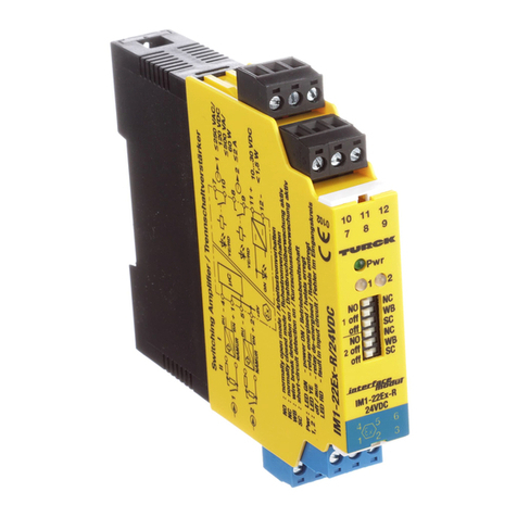
Temperature measuring amplifier
IME-TI-11Ex-Ci/24VDC
Short description
• Single-channel temperature measuring amplier
• Intrinsically safe input circuit Ex ia for connection of Pt100 and Ni100
resistance temperature detectors (RTDs), thermoelements, resistors
and potentiometers and low voltages (mV range)
• Connection of RTDs with 2-, 3- or 4-wire technology
• Thermoelement measuring with external, internal and constant cold
junction compensation
• Wire-break monitoring
• Short-circuit monitoring only of Pt100 or Ni100 RTDs
• Output circuit 0/4…20 mA, short-circuit protected
• Galvanic isolation between input and output circuits and power supply
• Application area according to ATEX: II (1) GD, II 3 G
• Approved for installation in zone 2
• Parameterization via PC via programming adapter IM-PROG III
(optionally available from TURCK, ident-no.: 6890422)
• Simulation of outputs
Terminal configuration (Fig. 2)
1, 2 Thermoelement and mV input
3 – 6 RTD, resistor and potentiometer input
9, 10 Analog current output (0/4...20 mA)
14, 13 Power supply
12, 11 Power supply looped in
Connection via cage-clamp terminals:
Connection prole 0.75 mm2…1.5 mm2or 0.5 mm2…1 mm2with wire
sleeves.
LED indications (Fig. 1 + 2)
Pwr green Power on
óred Error
Note: Status indications, see table 1 on page 2





























Fig. 1 Frontansicht
Front view
Fig. 2 Blockschaltbild
Circuit diagram
Temperaturmessverstärker
IME-TI-11Ex-Ci/24VDC
Gerätekurzbeschreibung
•Einkanaliger Temperaturmessverstärker
• Eigensicherer Eingangskreis Ex ia zum Anschluss von Pt100 and Ni100
Temperaturwiderständen (RTDs), Thermoelementen, Widerständen
und Potentiometer und Kleinspannungen (mV-Bereich)
•Anschluss von RTDs in 2-, 3- oder 4-Draht-Technik
•Thermoelentmessung mit externer, interner und konstanter Kaltstellen-
kompensation
•Drahtbruchüberwachung
•Kurzschlussüberwachung nur von Pt100- oder Ni100-RTDs
•Ausgangskreis 0/4…20 mA, kurzschlussfest
•Galvanische Trennung zwischen Eingangskreis und Ausgangskreis und
zur Versorgung
•Anwendungsbereich nach ATEX: II (1) GD, II 3 G
•Zugelassen für Einbau in Zone 2
•Parametrierung über PC mit dem Programmieradapter IM-PROG III
(optional bei TURCK verfügbar, Ident-Nr.: 6890422)
•Simulation der Ausgänge
Klemmenbelegung (Fig. 2)
1, 2 Thermoelement und mV-Eingang
3 – 6 RTD-, Widerstand- und Potentiometer-Eingang
9, 10 Analoger Stromausgang (0/4...20 mA)
14, 13 Betriebsspannung
12, 11 Betriebsspannung durchgeschlien
Anschluss über Federzugklemmen:
Anschlussquerschnitt 0,75 mm2…1,5 mm2oder 0,5 mm2…1 mm2mit Ader-
Endhülsen.
LED-Anzeigen (Fig. 1 + 2)
Pwr grün Betriebsbereitschaft
órot Fehler
Hinweis: Statusanzeigen, siehe Tabelle 1 auf Seite 2
Die Werte entsprechen der
Leuchtcharakteristik in %
The values agree with the
light characteristic in %
Parameterization and adjustments
The IME... is parameterized and monitored via the Device Type Manager for
IME-Ti...-Ci... (see also “PACTware™ and devices DTM software installation”,
D201354).
Use the TURCK adapter IM-PROG III to establish the connection between the
device and your PC.
Plug the 3.5 mm connector to the measuring amplier (PC-Connect) and the
RS232 connector to the serial interface of your PC.
The following adjustments are made via DTM:
– Mode
Selection of the connection element:
Pt/Ni100, thermoelement, mV input and selection of line compensation.
Settings adjusted in the "Mode" menu:
– Thermoelement
Type selection: E, J, K, N, R, S, T, L, B
Note: If the cables of the thermoelements are routed up to the tempera-
ture measuring amplier, TURCK suggests the use of a cold junction
compensation module.
– Connection mode of temperature resistor 2, 3 or 4-wire connection
technology
– Measuring range
The measuring range is dened by the lower and upper value of the con-
nection element. After selecting the connection mode, the DTM indi-
cates the measuring range.
These indications accord to the analog output signal of 0/4...20 mA.
The lower value accords to an output signal of 0/4 mA.
The adjusted upper value accords to an analog output signal of 20 mA.
– Output signal
The selection comprises 0...20 mA or 4...20 mA signals.
The adjusted values correspond to the adjusted lower and upper tem-
perature values.
– Line compensation
In case of 2-wire connections, the resistor can be adapted to the con-
nection cable. For this purpose it is necessary to short-circuit the measu-
ring point. The LEDs Pwr and óash alternately. If line compensation is
done (LED Pwr = 100 %, LED ó= 10 %), continue by removing the short-
circuit. The mode selected before line compensation remains.
– Error current
Either 0 mA or > 22 mA
Tabelle/Table 1: Statusanzeigen/Status indications
LED LED Output of error current Description
Pwr óAusgabe des Fehlerstromes Beschreibung
100 0 – Betrieb/Operation
100 10 4Eingangsfehler/Input error
10 100 4Softwarefehler/Software error
0 100 4Hardwarefehler/Hardware error
100 50 4Messspanne zu klein/Measuring span too short
100 50 – Messbereich außerhalb des Anwendungsbereichs des RTD bzw. Thermoelements/
Measuring range outside the operating range of the RTD or thermoelement
50 50
4Leitungsabgleich/Line compensation (LEDs ashing alternately)
100 50 4Leitungsabgleich nicht korrekt/Line compensation not correct
50 0 – Stromausgang und Grenzwertrelais im Simulationsbetrieb/Current output in
simultaneous operation
IME-TI-11Ex-Ci/24VDC
Parametrierung und Einstellungen
Die Parametrierung und Einstellung des IME… wird über den DTM für IME-
Ti…-Ci… durchgeführt (siehe auch beigefügte Dokumentation„Software-
Installation PACTware™ und Geräte-DTMs“, D201354).
Der TURCK-Adapter IM-PROG III dient zur Verbindung zwischen dem Gerät
und Ihrem PC.
Verbinden Sie dazu den 3,5-mm-Stecker mit dem Messverstärker (PC-Con-
nect) und den USB-Stecker mit dem PCs.
Die folgenden Einstellungen werden duch den DTM durchgeführt:
– Mode
Auswahl des Anschlusselementes:
Pt/Ni100, Thermoelement, mV-Eingang und Auswahl des
Leitungsabgleiches
– Thermoelement
Auswahl der Typen: E, J, K, N, R, S, T, L, B
Hinweis: Werden die Leitungen des Thermoelements bis zum Tempera-
turmessverstärker geführt, empehlt TURCK den Einsatz eines Kaltstel-
lenkompensationsmoduls.
– Anschlussart des Temperaturwiderstandes 2-, 3- oder 4-Leiter-Technik
– Messbereich
Der Messbereich ergibt sich aus eingestelltem Endwert und Anfangswert
des Anschlusselementes. Nach Auswahl des Anschlusstyps wird der
Messbereich in der DTM-Benutzeroberäche angezeigt.
Diese Angaben entsprechen dem analogen Ausgangssignal 0/4...20 mA.
Der eingestellte Anfangswert entspricht dem analogen Ausgangssignal
von 0/4 mA. Der eingestellte Endwert entspricht dem analogen Ausgangs-
signal von 20 mA.
– Ausgangssignal
Zur Auswahl stehen 0...20 mA bzw. 4...20 mA. Diese Werte entsprechen
den eingestellten Anfangs- und Endwerten.
– Leitungsabgleich
Beim 2-Leiter-Anschluss muss der Widerstand der Anschlussleitung
abgeglichen werden. Dazu ist die Messstelle kurzzuschließen.
Die LEDs Pwr und óblinken abwechselnd. Sobald der Abgleich beendet
ist (LED Pwr = 100 %, LED ó= 10 %), kann der Kurzschluss aufgehoben
werden. Der vor dem Abgleich gewählte Modus bleibt beibehalten.
– Fehlerstrom
Entweder 0 mA oder > 22 mA
2 /1012
Fig. 3 Kabelverbindung
Cable junction
Fig. 4 Maßzeichnung
Dimension drawing
IME-TI-11Ex-Ci/24VDC
Besondere Bedingungen für den Einsatz in Zone 2
Bei Einbau in Zone 2 muss das Gerät in ein Gehäuse nach EN 60079-15 mit
einer Schutzart mindestens IP54 nach IEC/EN 60529 montiert werden.
Bei Einbau in Zone 2 ist das Verbinden und Trennen der Anschlüsse von nicht
energiebegrenzten Stromkreisen unter Spannung nur zulässig, wenn keine
explosionsfähige Atmosphäre vorliegt.
Bei der Verdrahtung mit Litzendrähten sind die Drahtenden unbedingt mit
Aderendhülsen fest zu xieren.
Montage und Installation (Fig. 3 + 4)
Das Gerät ist aufschnappbar auf Hutschiene (EN 60715).
Geräte gleichen Typs können direkt aneinander gesetzt werden.
Sorgen Sie für eine ausreichende Wärmeabfuhr.
Führen Sie die Montage und Installation den gültigen Vorschriften entspre-
chend durch. Dafür sind Sie als Betreiber verantwortlich.
Schützen Sie das Gerät ausreichend gegen Staub, Schmutz, Feuchtigkeit
und andere Umwelteinüsse.
Auch gegen energiereiche Strahlung, Risiken mechanischer Beschädigung,
unbefugter Veränderung und zufälliger Berührung müssen Vorkehrungen
getroen werden.
Führen Sie sämtliche Installationen EMV-gerecht durch.
Die Verbindung der Kabel über Federzugklemmen wird in Fig. 3 dargestellt.
Special conditions for application in zone 2
For installation in zone 2 the device must be installed in a housing which
complies with the requirements of EN 60079-15 with a minimum protection
degree of IP54 according to IEC/EN 60529.
With mounting in zone 2 the connecting and disconnecting of energized
non energy limited circuits is only permitted in non-explosive atmosphere.
The application of litz-wires recommends the xation of cable ends with wire
sleeves.
Mounting and Installation (Fig. 3 + 4)
The device is suited for snap-on clamps for DIN rail mounting (EN 60715).
Devices of the same type may be mounted directly next to each other.
It must be ensured that heat is conducted away from the device.
Mounting and installation must be carried out in accordance with the
applicable regulations. The operator is responsible for compliance with the
regulations.
The device must be protected against dust, dirt, moisture and other environ-
mental inuences as well as against strong electromagnetic emissions.
It should also be protected against the risks of mechanical damaging, unau-
thorized access and incidental contact.
All installations must be carried out observing the regulations of EMC
protection.
The cable junction via cage-clamp terminals is shown in Fig. 3.




3 /1012
4 /1012
IME-TI-11Ex-Ci/24VDC
5 /1012
ì ì
Wichtige Hinweise zum Einsatz von Geräten mit eigen-
sicheren Stromkreisen
Das vorliegende Gerät verfügt an den blau gekennzeichneten Klemmen
über Stromkreise der Zündschutzart„Eigensicherheit“ für den Explosions-
schutz gemäß EN 60079-11.
Die eigensicheren Stromkreise sind von autorisierten Prüfungsstellen be-
scheinigt und für die Verwendung in den jeweiligen Ländern zugelassen.
Beachten Sie für den bestimmungsgemäßen Betrieb in explosionsgefähr-
deten Bereichen unbedingt die nationalen Vorschriften und Bestimmungen
und halten Sie diese ein. Die nicht eigensicheren Stromkreise sind entspre-
chend der nationalen Richtlinien anzuschließen.
Nachfolgend erhalten Sie einige Hinweise, insbesondere hinsichtlich der
Rahmen-Richtlinie der Europäischen Union 94/9/EG (ATEX).
Das vorliegende Gerät ist ein zugehöriges Betriebsmittel, das neben
eigensicheren auch über nichteigensichere Stromkreise verfügt. Es darf nur
außerhalb des Ex-Bereiches in trockenen, sauberen und gut überwachten
Räumen installiert werden.
Liegt eine Konformitätsaussage oder Erklärung des Herstellers als Gerät der
Kategorie 3 vor, darf eine Installation in Zone 2 und Zone 22 erfolgen. Die
besonderen Bedingungen zum sicheren Betrieb sind zu beachten.
An die eigensicheren Anschlüsse können eigensichere elektrische Betriebs-
mittel angeschlossen werden.
Alle Betriebsmittel müssen die Voraussetzungen zum Betrieb in der vorhan-
denen Zone des explosionsgefährdeten Bereiches erfüllen.
Führen die eigensicheren Stromkreise in staubexplosionsgefährdete Berei-
che der Zone 0 oder 1 bzw. 20 oder 21, ist sicherzustellen, dass die Geräte,
die an diese Stromkreise angeschlossen werden, die Anforderungen für
Kategorie 1GD bzw. 2GD erfüllen und entsprechend bescheinigt sind.
Werden die Geräte zusammengeschaltet, z. B. eigensichere Stromkreise,
muss der„Nachweis der Eigensicherheit“ durchgeführt werden
(EN 60079-14, Kap. 12.2.5).
Bereits durch den einmaligen Anschluss von eigensicheren Stromkreisen an
nicht eigensichere Kreise ist eine spätere Verwendung als Betriebsmittel mit
eigensicheren Stromkreisen nicht mehr zulässig.
Für die Errichtung eigensicherer Stromkreise, die Montage an äußeren
Anschlussteilen sowie für die Beschaenheit und Verlegung von Leitungen
gelten einschlägige Vorschriften.
Leitungen und Klemmen mit eigensicheren Stromkreisen müssen gekenn-
zeichnet werden – bei farbiger Kennzeichnung ist hellblau zu verwenden.
Sie sind von nichteigensicheren Stromkreisen zu trennen oder müssen eine
entsprechende Isolierung aufweisen (EN 60079-14).
Die Bereiche der Kontakte für die eigensicheren Stromkreise sind auf der
Geräteoberseite hellblau gekennzeichnet, so dass eine Verwechselung mit
anderen Stromkreisen ausgeschlossen ist. Bei der Verdrahtung der Geräte
sind geeignete Kabel zu verwenden. Sollen feldkonfektionierbare Stecker-
verbinder für die eigensicheren Stromkreise verwendet werden, so sind die
Anschlüsse mit Aderendhülsen (mit Kragen) zu versehen.
Halten Sie von den eigensicheren Anschlüssen dieses Gerätes den vorge-
schriebenen Abstand zu geerdeten Bauteilen und Anschlüssen anderer
Geräte ein.
Soweit nicht ausdrücklich in der gerätespezischen Anleitung angegeben,
erlischt die Zulassung durch Önen des Gerätes, Reparaturen oder Eingrie
am Gerät, die nicht vom Sachverständigen oder Hersteller ausgeführt werden.
Sichtbare Veränderungen am Gerätegehäuse, wie z. B. bräunlich-schwarze
Verfärbungen durch Wärme sowie Löcher oder Ausbeulungen weisen auf
einen schwer wiegenden Fehler hin. Daraufhin das Gerät unverzüglich
abschalten. Bei zugehörigen Betriebsmitteln müssen die angeschlossenen
eigensicheren Betriebsmittel ebenfalls überprüft werden. Die Überprüfung
eines Gerätes hinsichtlich des Explosionsschutzes kann nur von einem Sach-
verständigen oder vom Hersteller vorgenommen werden.
Der Betrieb der Geräte ist nur im Rahmen der auf dem Gehäuse aufgedruck-
ten bzw. in der Dokumentation aufgeführten zulässigen Daten gestattet.
Vor jeder Inbetriebnahme oder nach Änderung der Gerätezusammenschal-
tung ist sicherzustellen, dass die zutreenden Bestimmungen, Vorschriften
und Rahmenbedingungen eingehalten werden, ein bestimmungsgemäßer
Betrieb gegeben ist und die Sicherheitsbestimmungen erfüllt sind.
Die Montage und der Anschluss des Gerätes muss von geschultem und qua-
liziertem Personal mit Kenntnis der einschlägigen nationalen und anzu-
wendenden internationalen Vorschriften über den Ex-Schutz durchgeführt
werden. Die wichtigsten Daten aus der EG-Baumusterprüfbescheinigung sind
umseitig aufgeführt. Alle gültigen nationalen und internationalen Bescheini-
gungen der TURCK-Geräte nden Sie im Internet (www.turck.com). Weitere
Informationen zum Ex-Schutz stellen wir Ihnen auf Anfrage gern zur Verfügung.
Important information on use of devices with intrinsically
safe circuits
This device is equipped with circuits featuring protection type„intrinsic
safety“ for explosion protection per EN 60079-11 at terminals which are
marked in blue.
The intrinsically safe circuits are approved by the authorised bodies for use
in those countries to which the approval applies.
For correct usage in explosion hazardous areas please observe and follow
the national regulations and directives strictly.
Non-intrinsically save circuits have to be installed according to the national
regulations.
Following please nd some guidelines referring to the frame-work directive
of the European Union 94/9/EC (ATEX).
This device is classied as an associated apparatus which is equipped with
intrinsically safe and non-intrinsically safe circuits. Therefore it may only be
installed in the non-explosion hazardous area in dry clean and well monito-
red locations.
If a declaration of conformity or declaration of the manufacturer as a catego-
ry 3 device exists, the device may be installed in zone 2 and zone 22.
Special instructions for safe operation must be observed. .
It is permitted to connect intrinsically safe equipment to the intrinsically safe
connections of this device.
All electrical equipment must comply with the regulations applying to use
in the respective zone of the explosion hazardous area.
If the intrinsically safe circuits lead into explosion hazardous areas subject
to dust hazards, i.e. zones 0 and 1 or 20 and 21, it must be ensured that the
devices which are to be connected to these circuits, meet the requirements
of category 1GD or 2GD and feature an according approval.
When interconnecting devices i.e. connecting intrinsically save circuits to
other circuits, it is required to keep and provide a proof of intrinsic safety
(EN 60079-14, chap. 12.2.5).
Once that intrinsically safe circuits have been connected to the non-
intrinsically safe circuit, it is not permitted to use the device subsequently as
intrinsically safe equipment.
The governing regulations cover installation of intrinsically safe circuits,
mounting to external connections, cable characteristics and cable installa-
tion.
Cables and terminals with intrinsically safe circuits must be marked (use
light blue for coloured marking) and separated from non-intrinsically safe
circuits or feature appropriate isolation (EN 60079-14).
Those areas of the contacts related to the intrinsically safe circuits have to
be indicated in light blue on the top side of the device such that mismach is
not possible.
Appropriate cables have to be used for wiring. If eld wireable connectors
should be used together with intrinsically save circuits, the connector ends
have to be protected with wire end sleeves (plus collar).
Please observe the specied clearances between the intrinsically safe
connections of this device and the earthed components and connections of
other devices.
The approval expires if the device is repaired, modied or opened by a
person other than the manufacturer or an expert, unless the device-specic
instruction manual explicitly permits such interventions.
Visible damages of the device’s housing (e. g. black-brown discolouration
due to heat accumulation, perforation or deformation) indicate a serious
error and the device must be turned o immediately.
When using associated apparatus it is required to check the connected
intrinsically safe equipment too. This inspection may only be carried out by
an expert or the manufacturer.
Operation of the devices is only permissible in accordance with the allowed
specications which are printed on the housing and/or listed in the docu-
mentation.
Prior to initial set-up or after every alteration of the interconnection
assembly it must be assured that the relevant regulations, directives and
framework conditions are observed, that operation is error-free and that all
safety regulations are fullled. Mounting and connection of the device may
only be carried out by qualied and trained sta familiar with the relevant
national and international regulations of explosion protection.
The most important data from the EC type examination certicate are listed
on the right side. All valid national and international approvals covering
TURCK devices are obtainable via the Internet (www.turck.com).
Further information on explosion protection is available on request.
No. ................. TÜV 09 ATEX 555273 / TÜV 09 ATEX 555274 X / IECEx TUN 09.0012 X
U0 .............................................................................................................................................. ≤ 5 V
I0 .......................................................................................................................................... ≤ 2 mA
P0 ..................................................................................................................................... ≤ 2,5 mW
L0/C0
– Ex ia IIC...........................................................................................................100 mH / 2,2 µF
– Ex ia IIB ...........................................................................................................100 mH / 10 µF
– Ex nL IIC..........................................................................................................100 mH / 3,6 µF
– Ex nL IIB...........................................................................................................100 mH / 18 µF
Li/Ci ............................................................................................... vernachlässigbar/negligible
Tamb ................................................................................................................................ -25...+70 °C
7_3f12a.doc Stand: 001 vom 01.08.06
Konformitätserklärung Nr. 4011 M
Declaration of Conformity
Diese Konformitätserklärung entspricht der Europäischen Norm EN 45014 ”Allgemeine Kriterien für Konformitätserklärungen von
Anbietern”. Die Grundlage der Kriterien sind internationale Dokumente, insbesondere ISO/IEC Leitfaden 22, 1982: ”Information on
manufacturer’s declaration of conformity with standards or other technical specifications”.
This “Declaration of Conformity“ complies with the European Standard EN 45014 ”General criteria for a supplier’s declaration of
conformity”. These criteria are based on the relevant international documentation, particularly the ISO/IEC Guide 22, 1982:
”Information on the manufacturer’s declaration of conformity with standards or other technical specifications”.
Wir
/ We
HANS TURCK GMBH & CO KG
WITZLEBENSTR. 7, D - 45472 MÜLHEIM A.D. RUHR
erklären in alleiniger Verantwortung, dass die Produkte
declare under our sole responsibility that the products
Temperaturmessumformer Typ IME-TI-11Ex-Ci/24VDC
auf die sich die Erklärung bezieht, mit den folgenden Normen übereinstimmen
to which this declaration relates are in conformity with the following standards
EN 61326:2006
und wo anwendbar
and where applicable
EN 60079-0:2006 EN 60079-11:2007 EN 60079-15:2005 EN 61241-11:2006
Gemäß den Bestimmungen der Richtlinie
(falls zutreffend)
Following the provisions of Directive (if applicable)
EMV - Richtlinie
/ EMC Directive
2004 / 108 / EG 15. Dez. 2004
Richtlinie ATEX 100a
/ Directive ATEX 100a
94 / 9 / EG 23. März 1994
Weitere Normen
additional standards
Aussteller der EG-Baumusterbescheinigung:
TÜV NORD CERT GmbH
Langemarckstraße 20, 45141 Essen
Kenn-Nr. 0044, Registriernummer: TÜV 09 ATEX 555273 Kennzeichnung II (1) G, II (1) D
Kennzeichnung II 3 G
Mülheim, den 18.09.2009
(i.V. W. Stoll)
Ort und Datum der Austellung /
Place and date of issue
Name und Unterschrift des Befugten /
Name and signature of authorized person
Irrtümer und Änderungen vorbehalten / Subject to change without notice • © Hans Turck GmbH & Co. KG 2012
HansTurckGmbH&Co.KG • Witzlebenstraße 7 • 45472 Mülheim/Ruhr • Germany • Tel. +49 (0) 208/4952-0 • Fax +49 (0) 208/4952-264 • [email protected] • www.turck.com
*D201392ßß1012*
D201392 1012
Internet: www.turck.com →www.turck.de
EG-Baumusterprüfbescheinigung
EC-Type examination certificate
0102
II (1) G [Ex ia/ib] IIC/IIB / II (1) D [Ex iaD]
II 3 G Ex nA [nL] IIC/IIB T4
IME-TI-11Ex-Ci/24VDC

Other turck Amplifier manuals

turck IMXK12-DI Series User manual

turck

turck IMXK12-DI Series User manual

turck IME-DI-22Ex-R/24VDC User manual

turck

turck IME-DI-22Ex-R/24VDC User manual

turck IMC-DI-22Ex-PNO/24VDC User manual

turck

turck IMC-DI-22Ex-PNO/24VDC User manual

turck IM18-DI03-4S-5R-S Series User manual

turck

turck IM18-DI03-4S-5R-S Series User manual

turck IM34-11Ex-Ci/24VDC User manual

turck

turck IM34-11Ex-Ci/24VDC User manual

turck IMX18-DI03-4S-5R-S Series User manual

turck

turck IMX18-DI03-4S-5R-S Series User manual

turck IM1-12 R Series User manual

turck

turck IM1-12 R Series User manual

turck IM12-DI01 -2T Series User manual

turck

turck IM12-DI01 -2T Series User manual

turck IM12-DI-PP Series User manual

turck

turck IM12-DI-PP Series User manual

turck IM1-22Ex-R User manual

turck

turck IM1-22Ex-R User manual

turck IM18-DI03-4S-4T1R-S Series User manual

turck

turck IM18-DI03-4S-4T1R-S Series User manual

turck IMX12-TI02-1TCURTDR-1I-PR/24VDC User guide

turck

turck IMX12-TI02-1TCURTDR-1I-PR/24VDC User guide

turck MK1-22P-Ex0/24VDC User manual

turck

turck MK1-22P-Ex0/24VDC User manual

turck MK13-R-Ex0 User manual

turck

turck MK13-R-Ex0 User manual

turck IM1-451Ex-R User manual

turck

turck IM1-451Ex-R User manual

turck IMX18-DI03-4S-4T1R-S Series User manual

turck

turck IMX18-DI03-4S-4T1R-S Series User manual

turck IM1-231Ex-R User manual

turck

turck IM1-231Ex-R User manual

turck MK13-PF-Ex0/24VDC User manual

turck

turck MK13-PF-Ex0/24VDC User manual

turck IM12-22Ex-R User manual

turck

turck IM12-22Ex-R User manual

turck MK13-11AEx0-R Series User manual

turck

turck MK13-11AEx0-R Series User manual

turck MS15-231E 0-R Series User manual

turck

turck MS15-231E 0-R Series User manual

turck IM12-DI03-1S-2T User manual

turck

turck IM12-DI03-1S-2T User manual

turck IM(X)18-DI03-4S-4T1R User guide

turck

turck IM(X)18-DI03-4S-4T1R User guide

Popular Amplifier manuals by other brands

McIntosh MC402 Service manual

McIntosh

McIntosh MC402 Service manual

Cyrus DAC XP Signature User instructions

Cyrus

Cyrus DAC XP Signature User instructions

Duncan Convertible Head owner's manual

Duncan

Duncan Convertible Head owner's manual

PDA Range VL1 instructions

PDA Range

PDA Range VL1 instructions

Audio-Visual Station PA-1600 operating instructions

Audio-Visual Station

Audio-Visual Station PA-1600 operating instructions

Marantz MM8077 owner's manual

Marantz

Marantz MM8077 owner's manual

Chiayo APEX PRO Operation manual

Chiayo

Chiayo APEX PRO Operation manual

Arcam P1000 manual

Arcam

Arcam P1000 manual

Shure SE20 Professional product data

Shure

Shure SE20 Professional product data

Audio Note M3 Phono Owner's Information

Audio Note

Audio Note M3 Phono Owner's Information

gefran VDA-M instruction manual

gefran

gefran VDA-M instruction manual

Sansui C-1000 Service manual

Sansui

Sansui C-1000 Service manual

Bel Canto e.One C5i user guide

Bel Canto

Bel Canto e.One C5i user guide

powersoft K2 DSP+AESOP user guide

powersoft

powersoft K2 DSP+AESOP user guide

Pioneer A-105 operating instructions

Pioneer

Pioneer A-105 operating instructions

AR 681 Operating and service manual

AR

AR 681 Operating and service manual

Renkforce A-1000 operating instructions

Renkforce

Renkforce A-1000 operating instructions

Sansui AU-7700 Service manual

Sansui

Sansui AU-7700 Service manual

manuals.online logo
manuals.online logoBrands
  • About & Mission
  • Contact us
  • Privacy Policy
  • Terms and Conditions

Copyright 2025 Manuals.Online. All Rights Reserved.