manuals.online logo
Brands
  1. Home
  2. •
  3. Brands
  4. •
  5. TWM
  6. •
  7. Toy
  8. •
  9. TWM La-Flyer-40 User manual

TWM La-Flyer-40 User manual

Wing Span
Wing Area
Flying Weight
Fuselage Length
64 in / 1630 mm
657 sq in / 42.4 sq dm
5.1 lb / 2300 g
50 in / 1270 mm
Warning ! This model is not a toy.
It is designed for maximum performance. Please seek advice if one is not familiar with this kind
of engine powered precision model. Operating this model without prior preparation may cause
injuries. Remember, safety is the most important thing. Always keep this instruction manual
at hand for quick reference.
Requires :
4- channel radio w/ 4 standard servos
0.40-0.46 cu. in. displacement 2-stroke
* Specifications are subject to change without notice.*
INSTRUCTION MANUAL
Specifications
FACTORY PRE-FABRICATED
ALMOST-READY-TO-FLY (ARF) SERIES
MADE IN CHINA
E
A
D
R
-
Y
T
-
T
S
O
O
-
F
M
L
L
Y
A
A234PO28901305
P. 1
P. 3 - 12
Check all parts. If you find any defective or missing parts contact your local dealer. Please DRY FIT
and check for defects for all parts that will require CA or Epoxy for final assembly. Any parts you
find to be defective after the gluing process may be difficult to remove for warranty replacement. The
manufacturer will replace any defective parts but will extend to the parts that are good before
, not
gluing to defective parts during assembly.
Warranty will not cover any parts modified by customer.
INDE X
BEFORE YOU BEGIN
PARTS LIST
ASSEMBLY
P. 1
P. 2
P. 12
BEFORE YOU BEGIN
Read through the manual before you begin, so you will have an overall idea of what to do.
Symbols used throughout this instruction manual comprise of the following : -
1
2
3
SAFETY PRECAUTIONS
3mm
Do not overlook this symbol!
Cut off shaded portion.
Peel off shaded portion
covering film.
Pay close attention here!
Pierce the shaded portion
covering film.
Must be purchased separately!
Drill holes with the specified
diameter (here: 3mm).
Ensure smooth non-binding
movement while assembling.
Apply instant glue
(C.A.glue, super glue.)
Assemble left and right
sides the same way.
Apply epoxy glue.
Apply thread locker
A234PO28901305
P.2
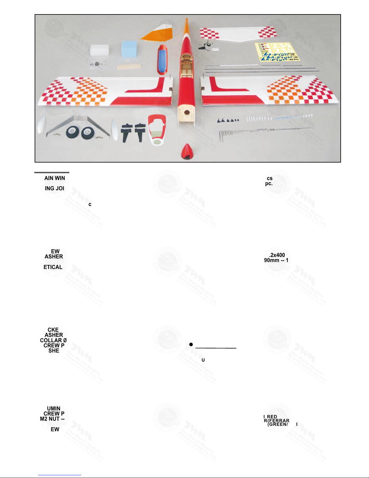
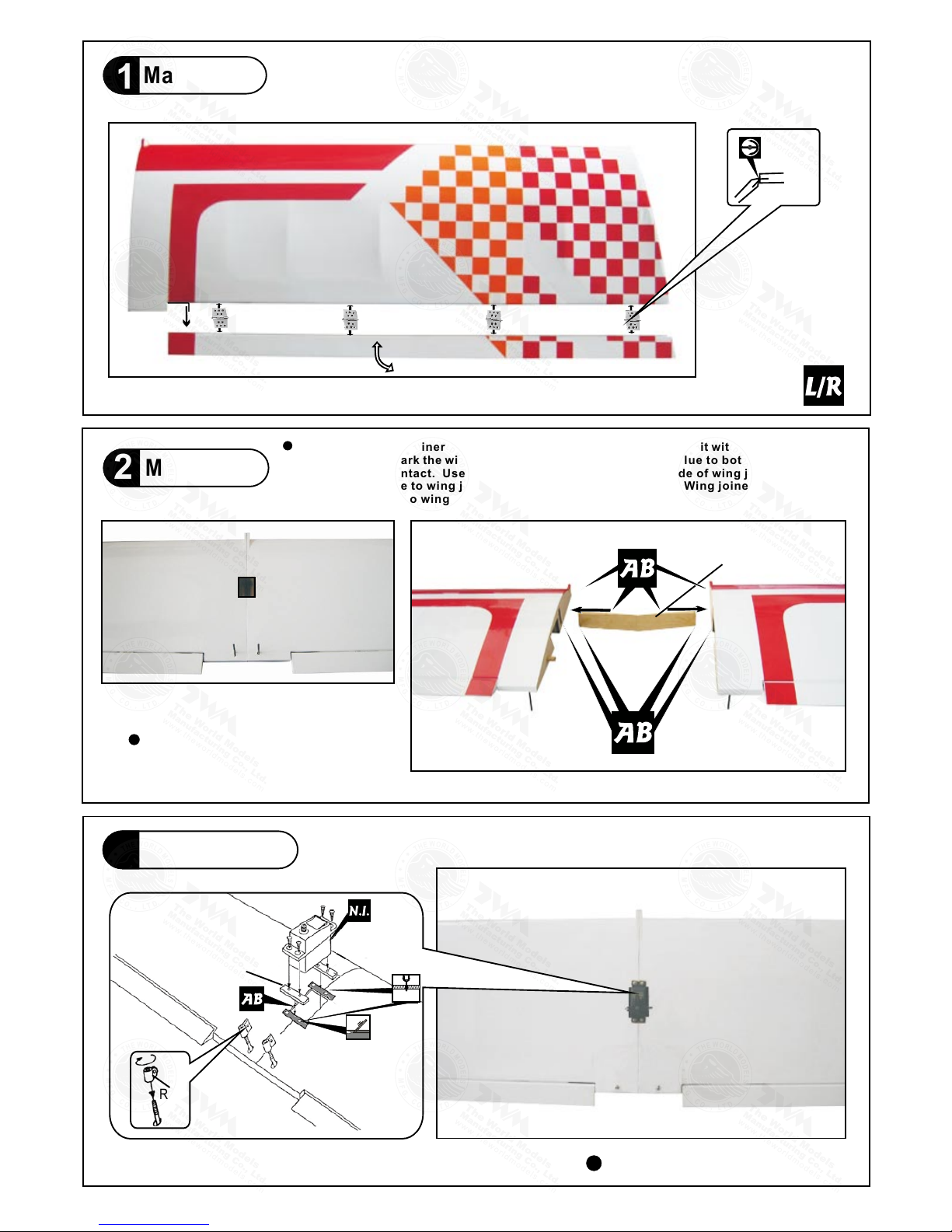
1. MAIN WING -- 1 pair
2. WING JOINER 8x25x201mm -- 1 pc.
3. PLYWOOD 3x10x20mm -- 2 pcs
RING Ø2.3mm -- 2 pcs
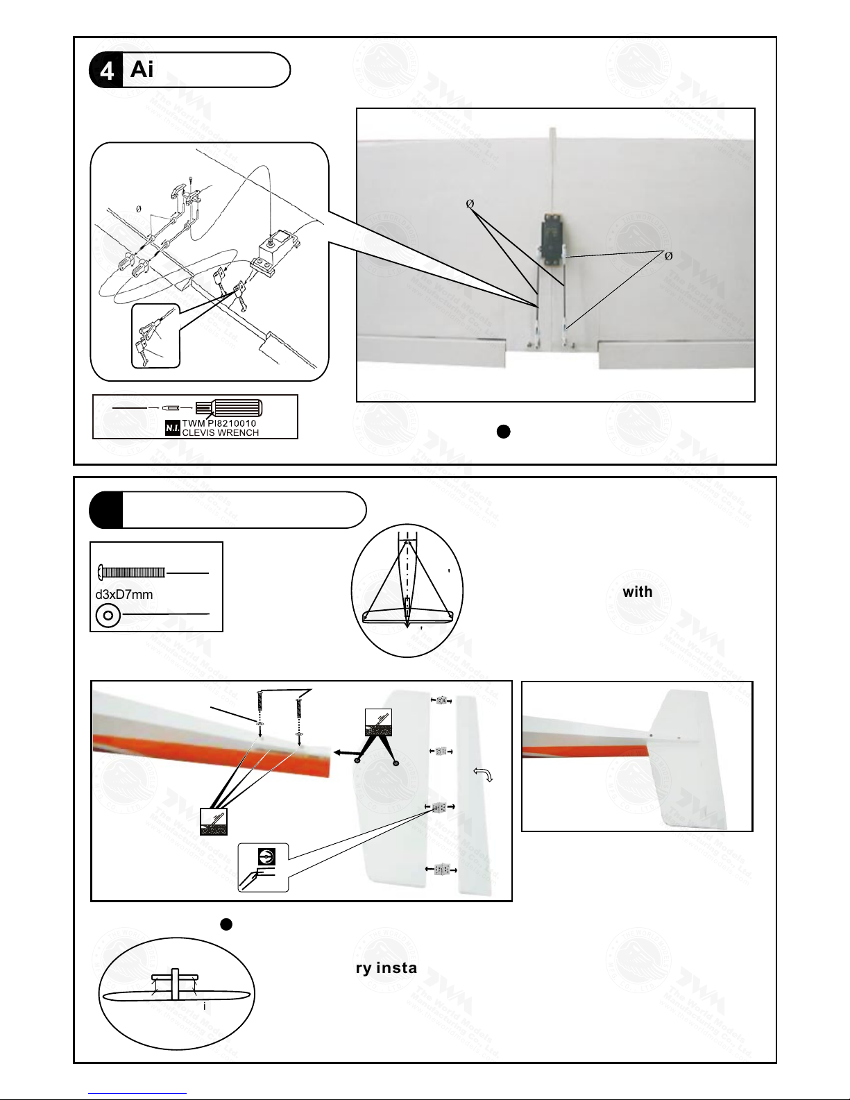
4. PUSHROD Ø1.8x100mm w/ Threads(For Aileron) -- 2 pcs
FUEL TUBE Ø6x5mm -- 4 pcs
STRAPER-- 2 pcs
CLEVIS-- 2 pcs
5. STABILZER & ELEVATOR -- 1 set
FUSELAGE -- 1 pc.
SCREW PM3x16mm -- 2 pcs
WASHER d3xD7mm -- 2 pcs
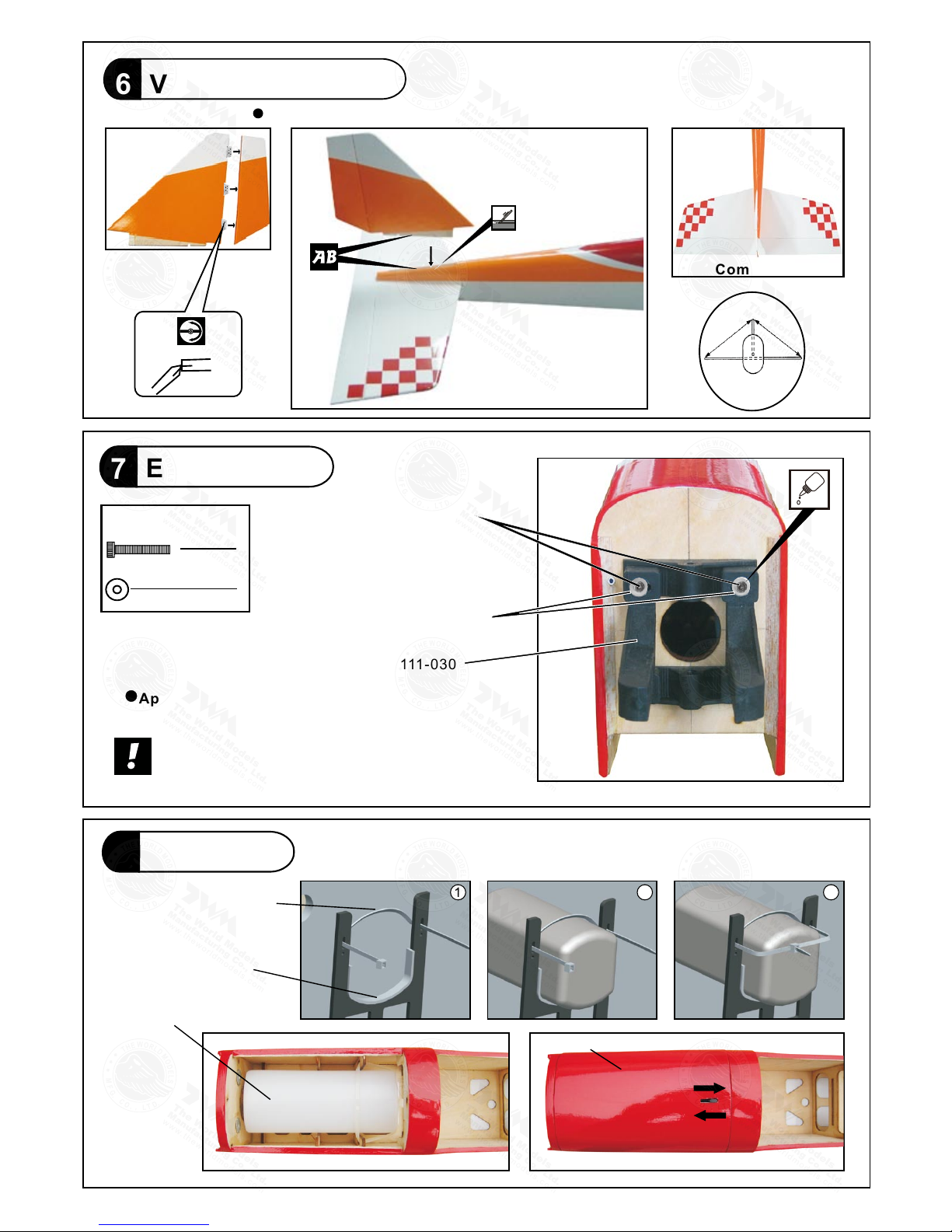
6. VETICAL FIN & RUDDER -- 1 set
7. ENGINE MOUNT PL511030 -- 1 set
SOCKET HEAD SCREW M3x20mm -- 4 pcs
WASHER d3xD7mm -- 4 pcs
8. FUEL TANK 320cc -- 1 set
CABLE TIE 1.5x5x400mm -- 1 pc
DOUBLE-SIDED TAPE 40x100mm -- 1 pc.
BATTERY COVER -- 1 pc.
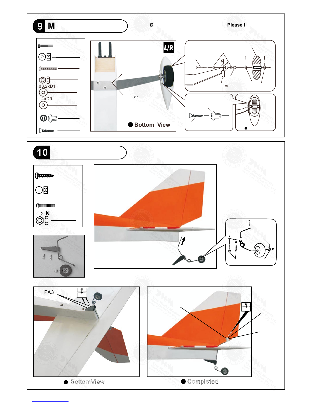
9. MAIN LANDING GEAR -- 1 set
SOCKET HEAD SCREW M3x14mm -- 3 pcs
WASHER d3.2xD12mm -- 3 pcs
COLLAR Ø4.1mm w/ set screw -- 4 sets
SCREW PM4x38mm -- 2 pcs
WASHER d4xD9mm -- 4 pcs
M4 NUT -- 2 pcs
QUICK RELEASE NYLON RIVET PL1208042 -- 4 pcs
MAIN WHEEL Ø62mm -- 2 pcs
ALUMINUM PLATE 1mm -- 2 pcs
WHEEL PANTS -- 1 pair
10. TAIL LANDING GEAR -- 1 set
SCREW PA3x12mm -- 2 pcs
COLLAR Ø2.1mm w/ set screw -- 1 set
TAIL WHEEL Ø25mm -- 1 pc.
ALUMINUM PLATE 0.3mm -- 1 pc.
SCREW PM2x10mm -- 1 pc.
M2 NUT -- 1 pc.
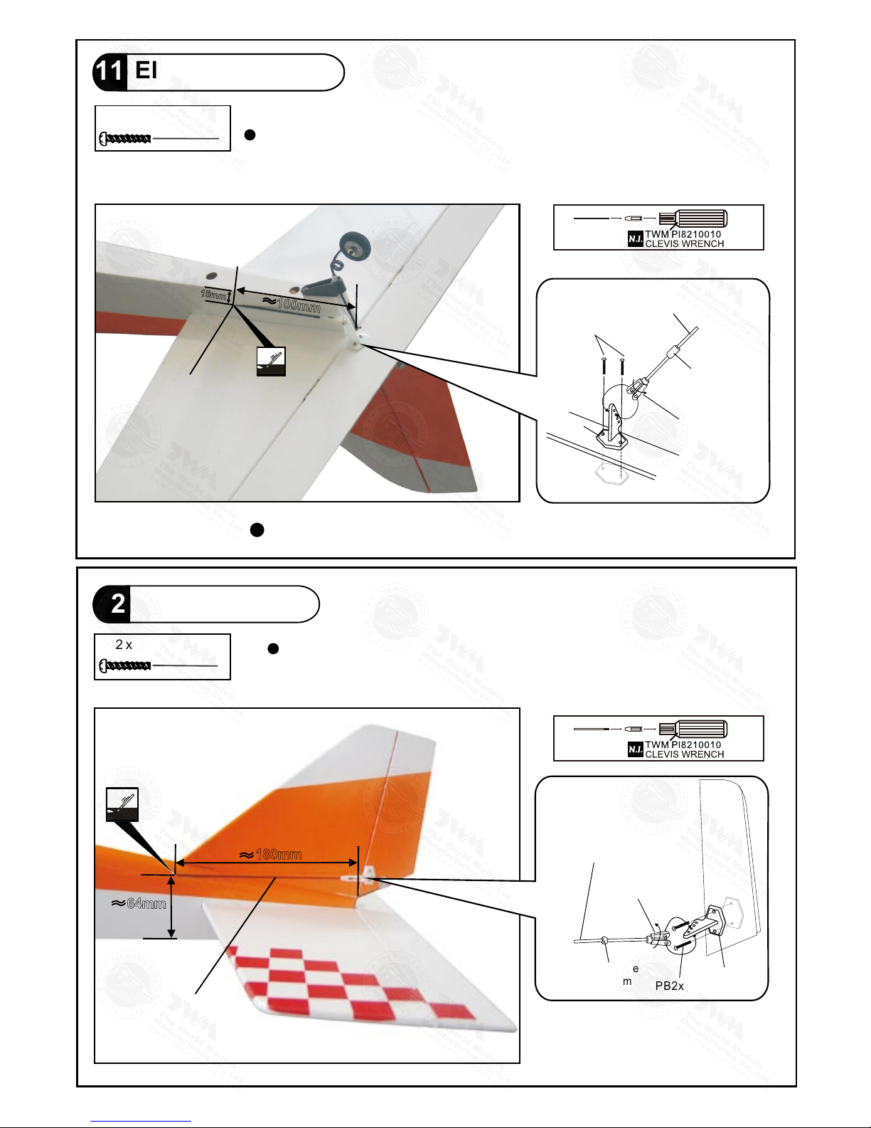
11. SCREW PB2x12mm -- 2 pcs
FUEL TUBE Ø6x5mm -- 1 pc.
CLEVIS -- 1 pc.
HORN -- 1 set
PUSHROD Ø1.8x720mm w/ Threads(For Elevator) -- 1 pc.
FUEL TUBE Ø6x5mm -- 1 pc.
CLEVIS -- 1 pc.
HORN -- 1 set
PUSHROD Ø1.8x720mm w/ Threads(For Rudder) -- 1 pc.
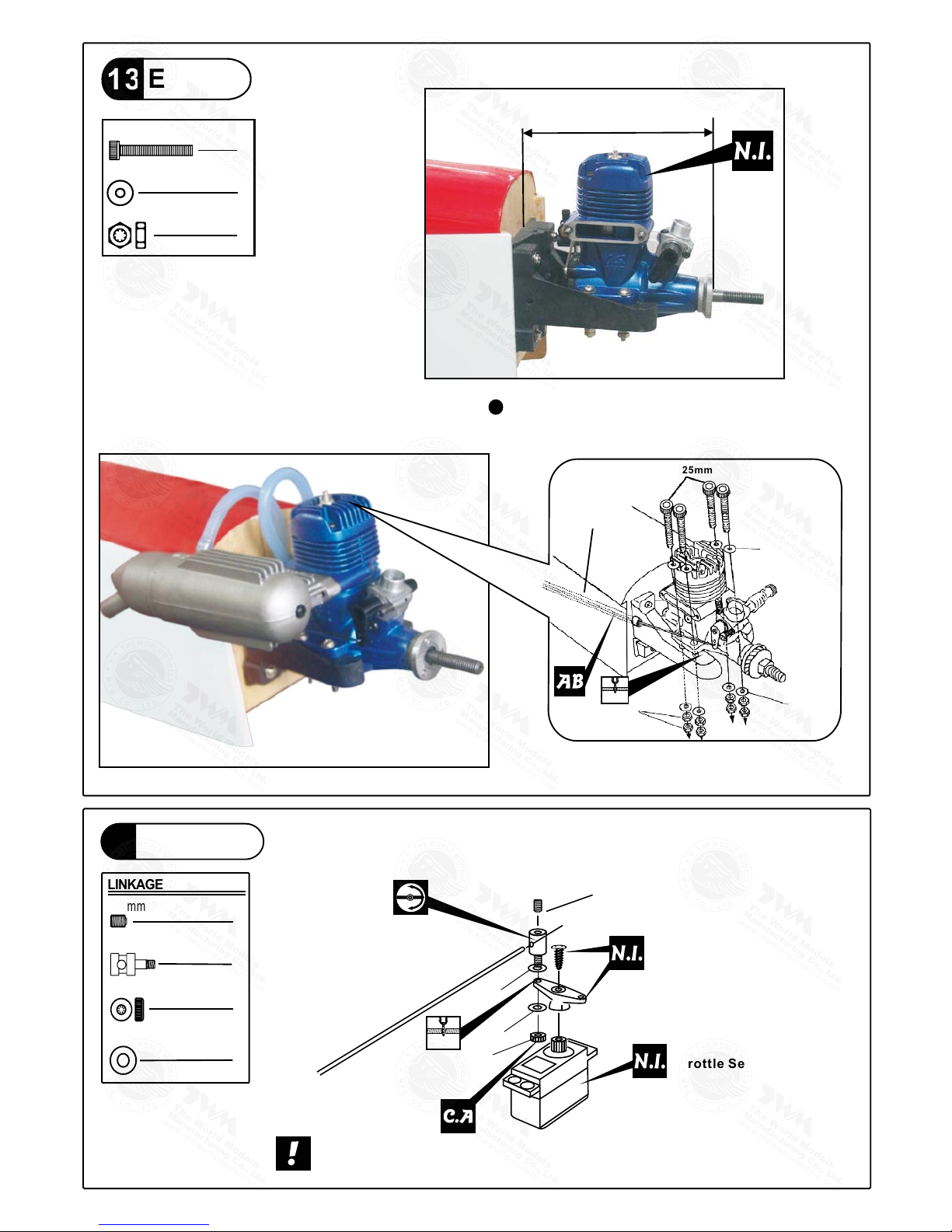
13. SOCKET HEAD SCREW M3x25mm -- 4 pcs
WASHER d3xD7mm -- 8 pcs
M3 NUT -- 8 pcs
14. LINKAGE CONNECTOR Ø2.1mm -- 1 set
15. SPONGE 60x70x80mm -- 1 pc.
FUEL TUBE Ø6x5mm -- 2 pcs
STRAPER -- 2 pcs
THROTTLE PUSH WIRE Ø1.2x400mm -- 1 pc.
w/ Plastic Tube d2xD3x190mm -- 1 pc.
16. CANOPY -- 1 pc.
PVC PLATE 1x14.3x78mm (Wing Protection) -- 1 pc.
SCREW HM4x35mm -- 2 pcs
WASHER d4xD12mm -- 2 pcs
17. COWLING -- 1 pc.
TRANSPARENT 3D TEMPLATE -- 1 pc.
SPINNER Ø57mm -- 1 set
SCREW PWA2.6x12mm -- 4 pcs
SILICON GROMMET d1.5xD6.5mm -- 4 pcs
18. DECALS
:
A234DEC – 1 set
12. SCREW PB2x12mm -- 2 pcs
Parts List
COVERING:--
BLACK COLOR SCHEME:
TOUGHLON STL 100 WHITE
TOUGHLON STL 201 BLACK
TOUGHLON STL 311 FERRARI RED
TOUGHLON STL 402 CHECKER(BLACK/WHITE)
TOUGHLON STL 412 CHECKER(FERRARI/WHITE)
ORANGE COLOR SCHEME:
TOUGHLON STL 100 WHITE
TOUGHLON STL 311 FERRARI RED
TOUGHLON STL 320 ORANGE
TOUGHLON STL 412 CHECKER(FERRARI/WHITE)
TOUGHLON STL 422 CHECKER(ORANGE/WHITE)
GREEN COLOR SCHEME:
TOUGHLON STL 100 WHITE
TOUGHLON STL 240 GREEN
TOUGHLON STL 311 FERRARI RED
TOUGHLON STL 412 CHECKER(FERRARI/WHITE)
TOUGHLON STL 442 CHECKER(GREEN/WHITE)
BLUE COLOR SCHEME:
TOUGHLON STL 100 WHITE
TOUGHLON STL 311 FERRARI RED
TOUGHLON STL 250 BLUE
TOUGHLON STL 412 CHECKER(FERRARI/WHITE)
TOUGHLON STL 452 CHECKER(BLUE/WHITE)
A234PO28901305
Main Wing
1
P.3
Make sure to glue securely.
If not properly glued, a failure
in fight may occur.
Main Wing
2
completed
Aileron Servo
3
Wing Joiner
8x25x201mm
1mm
Ring
Plywood
1.5mm
3x10x20mm
Bottom View
Pre-glued
1.5mm
Please dry fit wing joiner into left and right wing to make sure they fit with the proper
dihedral angle, mark the wing joiner if necessary. Apply epoxy glue to both sides of
all surfaces in contact. Use a stick to apply the glue to inner side of wing joiner sleeve,
and apply the glue to wing joiner before putting them together. Wing joiner not glued
properly will lead to wing failure and plane crash.
A234PO28901305
P.4
Stabilizer & Elevator
5
2
2
PM3x16mm Screw
d3xD7mm Washer
PM3x16mm
Washer
d3xD7mm
Completed
Temporary install the main wing, adjust
leveling of the stabilizer to make it as
parallel to the main wing as possible.
(Stabilizer)
(Main Wing)
BB'
B=B'
A=A
A
A
Aileron Servo
4
Fuel Tube
6 x 5mm
Pushrod 1.8x100mm
Straper
Fuel Tube
6x5mm
Ring
Clevis
Bottom View
Use thread locker when tightening
screw. Don't use excessive force
as you are dealing with balsa.
Bottom View
Pre-glued
A234PO28901305
P.5
Fuel Tank
8
Engine Mount PL5111-030
M3 x 20mm
Blind nuts are off-centered to keep
the spinner at the fuselage axis.
Apply thread locker to screws.
Engine Mount
7
Washer
d3xD7mm
4
4
d3xD7mm Washer
Vertical Fin / Rudder
6
P r e - g l u e d
C=
CC'
C'
Completed
M3x20mm
Socket Head Screw
Fuel Tank 320cc
1 2 3
Cable Tie
1.5x5x400mm
Double-sided Tape
40x100mm
Battery Cover
Remove coverings for all surfaces in contact before applying A/B epoxy glue.
A234PO28901305
Completed
P.6
Tail Landing Gear
10
BottomView
PA3x12mm Screw
2.1mm Collar
2
1
PM2x10mm Screw
M 2 N u t
1
1
PA3x12mm
Completed
PA3x12mm 2.1mm Collar
M3 Set Screw
PM2x10mm
Aluminum Plate
M2 Nut
2mm
2mm
Bottom View
PM4x38mm
Screw
M4 Nut
d3.2xD12mm Washer
Ø
marks at under side of fuselage.
1mm pilot holes are pre-drilled. Please look for pin-hole
Main Landing Gear
9
4.1mm
Collar
4
2
3
Plate 1mm
M3 x14mm
Washer
d3.2 xD12mm
M3x14mm Socket Head Screw
3Wheel Ø62
Washer d4xD9mm 3mm
Set Screw
Ø4.1 Collar
M4 Nut
PM4x38mm
3mm
Set Screw
KA2.3x8mm
d2xD8mm
Quick Release Nylon Rivet
2
d4xD9mm Washer
4
Quick Release Nylon Rivet
4
KA2.3x8mm Screw
4
A234PO28901305
Pushrod
Ø1.8x720mm
180mm
64mm
P.7
Elevator Pushrod
11
2
PB2 x 12mm Screw 1mm pilot holes for World Models tri-horn are pre-drilled.
Ø
Please look for pin-hole marks at under side of control surfaces.
Rudder Pushrod
12
2
PB2 x 12mm Screw 1mm pilot holes for World Models tri-horn are pre-drilled.
Ø
Please look for pin-hole marks at under side of control surfaces.
Pushrod
Ø1.8x720mm
15mm
100mm
Bottom View
Horn
Fuel Tube
6x5mm
Ø
Clevis
PB2x12mm
Pushrod
Ø1.8x720mm
Pushrod
Ø1.8x720mm
PB2x12mm
Clevis
Fuel Tube
Ø6x5mm Horn
A234PO28901305
P.8
3x3mm Set Screw
2mm Nut
Linkage Connector
1
1
1
2
2mm Washer
LINKAGE CONNECTOR
Servo Set
14
Engine
13
M3x25mm Socket Head Screw
d3xD7mm Washer
M3 Nut
4
8
8
Installed Engine Position
M3x25mm
Throttle Pushwire
w/plastic tube
3mm Washer
M3 Nut
3mm
Washer
3.2mm
100mm
3.93 in
3.2mm
Throttle pushwire
3mm
Included with the radio Set.
Throttle Servo.
2mm
M2 Nut
Please refer to attached sheet for linkage connector installation.
2mm
2mm
A234PO28901305
16 Main Wing & Canopy
2
2
HM4x35mm Screw
d4xD12mm Washer
Washer
d4xD12mm
HM4x35mm
Wing Protection
1x14.3x78mm
Install and arrange the servo as shown in the diagram.
Servos
15
Elevator Pushrod
Sponge
Throttle Pushwire
Ø1.2x400mm
Rudder Pushrod
Fuel Tube
Ø6x5mm
18
17
Cowling
4
4
PWA2.6x12mm Screw
d1.5xD6.5mm Silicon Grommet
Spinner Ø57mm
1mm
P.9
Front
First insert the grommet to the cowling then apply screw.
1mm
Please refer to the attached sheet for usage of the
transparent 3D template.
Elevator Servo
Rudder Servo
Throttle Servo
Battery
Switch Harness
Receiver
PWA2.6x12mm
Silicon Grommet
d1.5xD6.5mm
Cowling
Fuselage
Charge Receptacles
KP0041300
straper
A234PO28901305
P.10
Adjust the wing and fuselage configuration as shown
in the diagrams.
C = C'
A = A'
B = B'
Wing Setting
18
C'C
A
B B'
A'
A234PO28901305
#First time flyer should never fly by himself / herself. Assistance from experienced flyer is
absolutely necessary.
#Pre-flight adjustment must be done before flying, it is very dangerous to fly a badly
pre-adjusted aircraft.
# is specially designed to be powered by 2-stroke 0.40~0.46
engine, using a more powerful engine does not mean better performance. In fact, over
powered engine may cause severe damage and injuries.
#Make sure the air field is spacious, never fly the plane too close to people and never get
too close to a running propeller.
#If you find wrinkles on the covering as a result of weather changes, you can use hot iron
to remove the wrinkles. Please begin with lower temperature setting and gradually raise
the temperature until the wrinkles are gone. Too hot an iron may damage the covering.
Don't use hot iron near the seams or edges, hot iron will melt the glue and shrink
the covering at the same time, causing the seams to pull away.
#Check and re-tighten up all factory assembled screws, use thread locker if necessary.
Control Throws
19
Elevator
Rudder
Aileron
Important Safety Precautions
C.G.
20
C.G.
81mm
3.19in
6 mm
6 mm
Adjust the control throws as shown in
the diagram. These throws are good for
general flying. You can adjust according
to your personal preference.
The ideal C.G. position is 81mm (3.19 in) behind the leading edge
measured at where the wing meets the fuselage. In order to obtain
the C.G. specified, add weight to the fuselage or move the battery
position. Check the C.G. before flying.
If you are converting this model to electric, please move the C.G.
forward 10% of current C.G. distance from leading edge to
compensate for weight of fuel.
15 mm
15 mm
20 mm
20 mm
Warning!
P.11
http://www.theworldmodels.com/para/instruction/instructionManuals.php
A234PO28901305
LINKAGE CONNECTOR
HW7111050 & HW7111060
Drill 2mm hole at servo horn.
Insert linkage connector
into servo horn.
Make sure shoulder of
screw is cleared from
servo horn.
Add washer to reduce
play if necessary.
Shoulder
Tighten up the round nut
against the shoulder. Apply
CA or permanent thread
locker.
After fastening the round nut, make sure that
the linkage connector can rotate freely.
Product Registration Form (US Customers)
We would like to share with you any relevant information regarding your model, including
product news and free upgrade parts when applicable. Please fill in the following and send to
1.Name:
2.Address:
3.Phone #: e-mail:
4.Model:
Wing QC# Fuselage QC#
(QC numbers are stamped on wing and fuselage)
5.Date of Purchase:
6.Store Name:
Please call AirBorne Models at 925 371 0922 for any assistance in filling this form.
Thank you very much for purchasing our product.
Air orne Models, 4749-K,Bennett Drive, Livermore, CA 94551 USAB .
A234PO28901305
12
34
Usage of the transparent 3D template
This transparent 3D template
is used for position guidance
of the actual cutting of the
pre-painted cowling.
Simply cut the transparent 3D template to fit your engine and
exhaust pipe, then slide onto the actual cowling and use as
template to mark the openings required for final cutting.
P. 1 2
A234PO28901305
Optional Parts
180mm Extension
KW0011800 180mm 1 set
Code No. Size Package
Fuel Filler
PL8110030 15 x 22 x 49mm 1 x 1 pc
Code No. Size Package
Charge Receptacles
KP0041300
Code No. Size Package
Field Stand
MS9111450 600 x 240 x 350mm 1 pc
Code No. Size Package
180mm Y-Cord
KW0021800 180mm 1 pc
Code No. Size Package
Clevis Wrench
PL8210010 1 set
Code No. Size Package
Small Clevis Large Clevis
Special tool for clevis installation.
Suitable for standard and small
(EP) clevis.
Standard Servo
Code No SV4031
0.14 sec / 60° @6.0V
Torque : 3.2kg.cm / 44.8 oz - in @4.8V
4.1kg.cm / 57.4 oz - in @6.0V
Size : 40.6 x 20 x 37mm /
1.60 x 0.79 x 1.46 in
Weight : 39.4 g / 1.39 oz
Speed : 0.17 sec / 60° @4.8V
A234PO28901305
The World Models
Manufacturing Co., LTD.
www.theworldmodels.com
A234PO28901305

Other TWM Toy manuals

TWM EXTRA 330L 60 User manual

TWM

TWM EXTRA 330L 60 User manual

TWM UniJet User manual

TWM

TWM UniJet User manual

TWM Sky Link EP User manual

TWM

TWM Sky Link EP User manual

TWM 1/3 CLIPPED WING CUB User manual

TWM

TWM 1/3 CLIPPED WING CUB User manual

TWM P-51D Strega-40 User manual

TWM

TWM P-51D Strega-40 User manual

TWM Ultimate-90 User manual

TWM

TWM Ultimate-90 User manual

TWM Extra 300 EP (40) User manual

TWM

TWM Extra 300 EP (40) User manual

TWM INTRUDER 90R User manual

TWM

TWM INTRUDER 90R User manual

TWM 1/4 Clipped Wing Cub User manual

TWM

TWM 1/4 Clipped Wing Cub User manual

TWM Zero Fighter 60S User manual

TWM

TWM Zero Fighter 60S User manual

TWM AT-6 TEXAN EP User manual

TWM

TWM AT-6 TEXAN EP User manual

TWM INTRUDER 90R User manual

TWM

TWM INTRUDER 90R User manual

TWM 1/3 SUPER CUB User manual

TWM

TWM 1/3 SUPER CUB User manual

TWM Super Chipmunk-90 RF User manual

TWM

TWM Super Chipmunk-90 RF User manual

TWM MENTOR T-34 User manual

TWM

TWM MENTOR T-34 User manual

TWM WORLD STAR 40 F User manual

TWM

TWM WORLD STAR 40 F User manual

TWM LA Racer-40 User manual

TWM

TWM LA Racer-40 User manual

TWM 1/3 PAULISTINA P-56 User manual

TWM

TWM 1/3 PAULISTINA P-56 User manual

TWM KATANA User manual

TWM

TWM KATANA User manual

TWM 1/3 SUPER CUB User manual

TWM

TWM 1/3 SUPER CUB User manual

TWM Ultimate-40S User manual

TWM

TWM Ultimate-40S User manual

TWM Bard User manual

TWM

TWM Bard User manual

TWM SPITFIRE G.S User manual

TWM

TWM SPITFIRE G.S User manual

TWM Ultimate-90 User manual

TWM

TWM Ultimate-90 User manual

Popular Toy manuals by other brands

Phoenix Model DECATHLON MK2 instruction manual

Phoenix Model

Phoenix Model DECATHLON MK2 instruction manual

Model Rockets BOOSTAR-C Assembly instructions

Model Rockets

Model Rockets BOOSTAR-C Assembly instructions

REVELL Ju 52/3mg 4e military manual

REVELL

REVELL Ju 52/3mg 4e military manual

REVELL Control TURACO user manual

REVELL

REVELL Control TURACO user manual

X4-TECH Bobby Joey Fairytale Owl user manual

X4-TECH

X4-TECH Bobby Joey Fairytale Owl user manual

Canon CREATIVE PARK 3D Decoupage Assembly instructions

Canon

Canon CREATIVE PARK 3D Decoupage Assembly instructions

SL Model SL-30 instruction manual

SL Model

SL Model SL-30 instruction manual

MGA Entertainment Ultra Hair Surprise 563822 quick start guide

MGA Entertainment

MGA Entertainment Ultra Hair Surprise 563822 quick start guide

Makeblock mDrawBot Kit user manual

Makeblock

Makeblock mDrawBot Kit user manual

Hangar 9 Piper Pawnee 40 ARF Assembly manual

Hangar 9

Hangar 9 Piper Pawnee 40 ARF Assembly manual

Mattel Hot Wheels Trick Tracks Ultimate Stunt World instructions

Mattel

Mattel Hot Wheels Trick Tracks Ultimate Stunt World instructions

Eduard P-47D-25 Thunderbolt manual

Eduard

Eduard P-47D-25 Thunderbolt manual

Fisher-Price R9698 manual

Fisher-Price

Fisher-Price R9698 manual

Hasbro Disney Princess Secret Styles instructions

Hasbro

Hasbro Disney Princess Secret Styles instructions

Fisher-Price B9172 instructions

Fisher-Price

Fisher-Price B9172 instructions

LEGO Dump Gear Attachment Assebly instructions

LEGO

LEGO Dump Gear Attachment Assebly instructions

Faller 130175 instructions

Faller

Faller 130175 instructions

Hornby Railroad Compound Class Operating and maintenance instructions

Hornby

Hornby Railroad Compound Class Operating and maintenance instructions

manuals.online logo
manuals.online logoBrands
  • About & Mission
  • Contact us
  • Privacy Policy
  • Terms and Conditions

Copyright 2025 Manuals.Online. All Rights Reserved.