TWM EXTRA 330L 60 User manual

Wing Span
Wing Area
Flying Weight
Fuselage Length
65.0 in / 1650mm
797 sq in / 51.4 sq dm
8.2 lbs / 3720g
56.0 in / 1420mm
Warning !This model is not a toy.
It is designed for maximum performance. Please seek advice if one is not familiar with this kind
of engine powered precision model. Operating this model without prior preparation may cause
injuries. Remember, safety is the most important thing. Always keep this instruction manual at
hand for quick reference.
* Specifications are subject to change without notice.*
Specifications
INSTRUCTION MANUAL
E
A
D
R
-
Y
T
-
T
S
O
O
-
F
M
L
L
Y
A
0.6 -0.75 cu. in. displacement 2-stroke
0.91 cu. in. displacement 4-stroke
0
R s - radio w/ standard equire : 4 channel 5 servos
FACTORY PRE-FABRICATED
ALMOST-READY-TO-FLY (ARF) SERIES
MADE IN CHINA
A156SPO25891108

P.1
Apply thread locker
Apply epoxy glue.
Pierce the shaded portion
covering film.
Apply instant glue
(C.A.glue, super glue.)
Ensure smooth non-bindin g
movement while assembling.
Do not overlook this symbol !
Check all parts. If you find any defective or missing parts contact your local dealer. Please DRY FIT
and check for defects for all parts that will require CA or Epoxy for final assembly. Any parts you
find to be defective after the gluing process may be difficult to remove for warranty replacement. The
manufacturer will replace any defective parts, but will not extend to the parts that are good before
gluing to defective parts during assembly. Warranty will not cover any parts modified by customer.
Read through the manual before you begin, so you will have an overall idea of what to do.
Symbols used throughout this instruction manual comprise of the following : -
1
2
3
Assemble left and right
sides the same way.
Peel off shaded portion
covering film.
Drill holes with the specified
diameter (here: 3mm) .
Pay close attention here!
Cut off shaded portion.
Must be purchase d separately !
Warning!
3mm
P. 3 -11
INDEX
BEFORE YOU BEGIN
PARTS LIST
ASSEMBLY
SAFETY PRECAUTIONS
P. 1
P. 2
P.11
BEFORE YOU BEGIN
A156SPO25891108

Parts List
COVERING:--
TOUGHLON STL 100 WHITE
TOUGHLON STL 201 BLACK
TOUGHLON STL 241 TURQUOISE
TOUGHLON STL 360 VIOLET
TOUGHLON STL 311 FERRARIRED
TOUGHLON STL 351 DARK BLUE
P.2
1. MAIN WING -- 1 pair
2. SCREW PB2x25mm -- 6 pcs
SCREW PWA2x8mm -- 8 pcs
FUEL TUBE Ø6x5mm -- 4 pcs
STRAPER PL4112102 -- 2 pcs
CLEVIS PL4112103 -- 2 pcs
TRI-HORN M3x14mm PL4111185 -- 2 sets
PUSHROD Ø1.8x120mm w/ Threads (For Aileron) -- 2 pcs
SERVO MOUNTING PANEL PL5310000-- 1 pair
3. STABILIZER & ELEVATOR -- 1 set
FUSELAGE -- 1 pc.
4. VERTICAL FIN & RUDDER -- 1 set
5. TAIL LANDING GEAR PL7100001 -- 1 set
TAIL WHEEL Ø30mm -- 1 pc.
COLLAR Ø2.1mm w/ set screw -- 1 set
SCREW PA3x12mm -- 2 pcs
6. SCREW PM2x25mm -- 3 pcs
M2 NUT -- 3 pcs
FUEL TUBE Ø6x5mm -- 2 pcs
CLEVIS PL4112103 -- 2 pcs
TRI-HORN M3x14mm (w/ o-Base For Rudder) PL4111185 -- 2 sets
RIGGING COUPLER Ø1.8x27mm w/ Threads HW4201304 -- 2 pcs
COPPER TUBE d2.5xD3.2x8mm --2 pcs
WIRE Ø1x700mm (For Rudder) -- 2 pcs
7. SCREW PB2x25mm -- 6 pcs
FUEL TUBE Ø6x5mm -- 2 pcs
CLEVIS PL4112103 -- 2 pcs
TRI-HORN M3x14mm (For Elevator) PL4111185 -- 2 sets
PUSHROD Ø1.8x600mm w/ Threads (For Elevator) -- 2 pcs
8. MAIN LANDING GEAR HW2404045 -- 1 set
MAIN LANDING GEAR COVER -- 1 pair
WHEEL Ø76mm PL3111760 -- 2 pcs
COLLAR Ø5.1mm w/ set screw -- 4 sets
SCREW HM4x16mm -- 4 pcs
SCREW PM5x43mm -- 2 pcs
SCREW PWA2.3x8mm -- 14 pcs
SCREW KA2.3x8mm -- 4 pcs
M5 NUT -- 2 pcs
WASHER d5xD12mm -- 4 pcs
QUICK RELEASE NYLON RIVET PL1208042 -- 4 pcs
WHEEL PANTS -- 1 pair
WHEEL PANT DECORATIVE COVER -- 1 pair
PLASTIC WHEEL COLLAR d5.1xD9x3mm -- 2 pcs
ALUMINUM PLATE 1mm -- 2 pcs
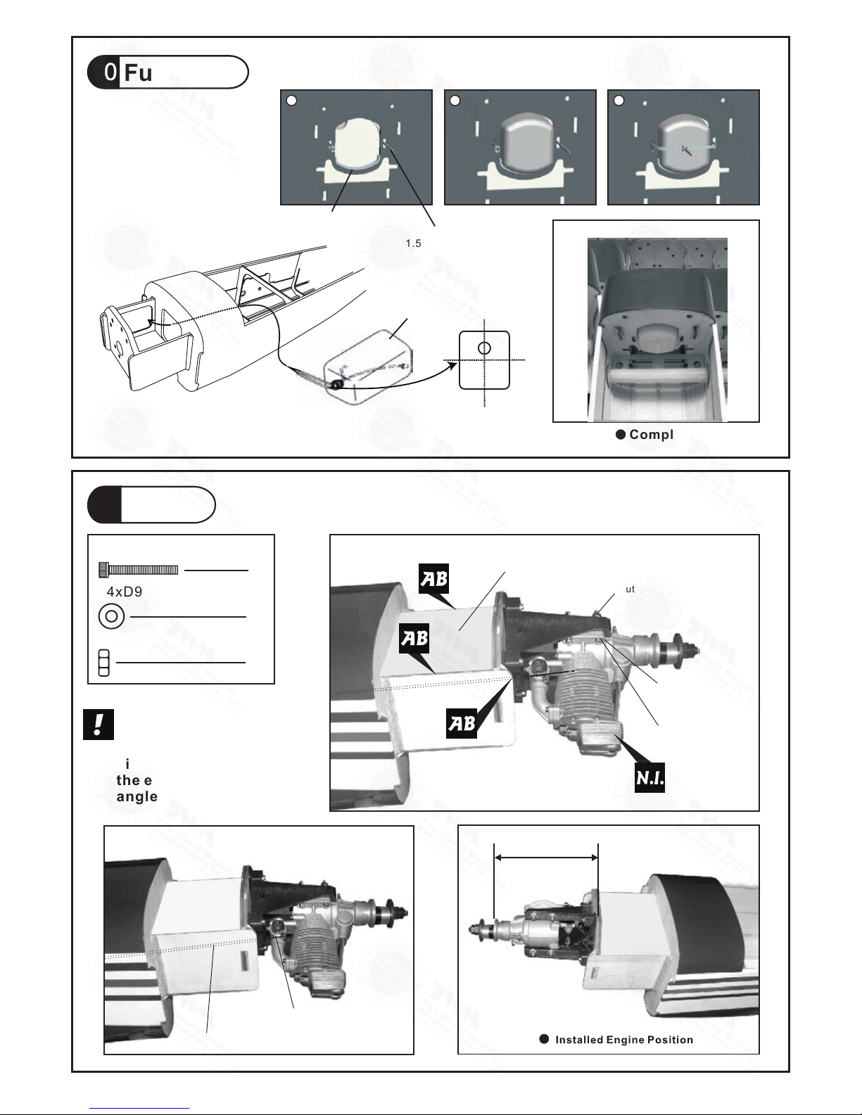
9. ENGINE MOUNT PL5111070 -- 1 set
SOCKET HEAD SCREW M4x25mm -- 4 pcs
WASHER d4xD12mm -- 4 pcs
M4 BLIND NUT -- 4 pcs
WOODEN DOWEL Ø5.5x8mm (For Firewall) -- 4 pcs
10. FUEL TANK 380cc PL1111380 -- 1 set
DOUBLE-SIDED TAPE 40x100mm -- 1 pc.
CABLE TIE 1.5x5x400mm -- 1 pc.
11. SOCKET HEAD SCREW M4x30mm -- 4 pcs
WASHER d4xD9mm -- 8 pcs
M4 NUT -- 8 pcs
PLYWOOD 2x93.8x120mm (Engine Box Upper Plate) (F21) -- 1 pc.
THROTTLE PUSHWIRE Ø1.2x350mm -- 1 pc.
PLASTIC TUBE d2xD3x140mm -- 1 pc.
12. LINKAGE CONNECTOR Ø2.1mm HW7111060 -- 1 set
13. BALSA 6x6x41 (For Elevator & Rudder Servo Stand) (F43) -- 4 pcs
PLYWOOD 3x57x154.6mm (For Elevator Servo)( F44A) -- 1 pc.
BALSA 6x6x143.6mm (For Elevator Servo) (F45B) -- 1 pc.
BALSA 6x6x150.3mm (For Elevator Servo) (F45C) -- 1 pc.
PLYWOOD 3x61x144.6mm (For Rudder Servo) (F44) -- 1 pc.
BALSA 6x6x131.5mm (For Rudder Servo) (F45) -- 1 pc.
BALSA 6x6x140.7mm (For Rudder Servo) (F45A) -- 1 pc.
COPPER TUBE d2.5xD3.2x8mm -- 2 pcs
STRAPER PL4112102 -- 1 pc.
FUEL TUBE Ø6x5mm -- 1 pc.
SPONGE 60x70x160mm (For Radio Equipment) -- 1 pc.
PUSHROD Ø1.8x100mm (For Elevator) -- 1 pc.
RIGGING Z BEND Ø1.8x27mm (For Rudder ) HW4201303 -- 2 pcs
PUSHROD CONNECTOR 4x9x20mm PL4410010 -- 1 set
14. COWLING -- 1 pc.
TRANSPARENT 3D TEMPLATE -- 1 pc.
SPINNER Ø70mm PH24W0700 / PH24B0700 -- 1 set
SCREW PWA2.6x12mm -- 4 pcs
SILICON GROMMET d1.5xD6.5mm -- 4 pcs
15. WING TUBE Ø22x814mm -- 1 pc.
WIRE Ø0.8mm -- 2 pcs
SELF-TIGHTENING LATCHING PIN -- 2 pcs
16. CANOPY -- 1 pc.
PILOT PC001085A -- 1 pc.
SCREW PM2.5x25mm -- 2 pcs
SCREW PWA2.3x8mm -- 6 pcs
SILICON GROMMET d1.5xD6.5mm -- 6 pcs
WASHER d2.5xD8mm -- 2 pcs
DOUBLE-SIDED TAPE 900mm -- 1 pc.
PLASTIC PLATE (For Pilot Stand) -- 1 pc.
17. DECALS: A156DEC -- 1 set
A156SPO25891108

Main Wing
1
Aileron Servo
2
Bottom View
6
PB2x25mm Screw
8
PWA2x8mm Screw
Fuel Tube
Ø6x5mm
PB2x25mm
Tri-horn
M3x14mm
Clevis
Pushrod
Ø1.8x120mm
Fuel Tube
Ø6x5mm
Straper
PWA2x8mm
1mm
PWA2 x 8mm
Aileron Servo Lead
Bottom View
P.3
Ø1mm pilot holes for World Models tri-horn are pre-drilled.
Please look for pin-hole marks at under side of control surfaces.
Apply instant type CA gule to both sides of each hinge.
A156SPO25891108

Apply instant type CA glue to
both sides of each hinge.
Stabilizer Elevator &
3
Apply instant type CA glue to
both sides of each hinge.
A=A
A
A
Completed
(Stabilizer)
(Main Wing)
BB'
B
B
Temporary install the main wing, adjust leveling
of the stabilizer to make it as parallel to the main
wing as possible.
C=C'
CC
Completed
5Tail Landing Gear
2.1mm Collar
2
PA3 x 12mm Screw
2
M3 x 3mm
Set Screw
PA3 x 12mm
2.1mm Collar
Bottom View
P.4
1.5mm
2.1mm
A156SPO25891108

Rudder Pullwire
6
PM2x25mm Screw
3
149mm
36mm
Clevis
Rigging Coupler
Ø1.8 x 27mm
Fuel Tube
6x5mmØ
2mm
Ring
Copper Tube
7Elevator Pushrod
PB2x25mm Screw
6
Bottom View
Elevator Pushrod
Fuel Tube
Ø6x5mm
Tri-horn
M3x14mm
Ø1.8x600mm
PB2x25mm
176mm
PM2x25mm
M2 Nut
71mm
3
M2 NUT
Bottom View
Bottom View
P.5
Ø1mm pilot holes for World Models tri-horn are pre-drilled.
Please look for pin-hole marks at under side of control surfaces.
Ø1mm pilot holes for World Models
tri-horn are pre-drilled. Please look
for pin-hole marks at side of control
surfaces.
2mm
A156SPO25891108

8Main Landing Gear
2
4
PWA2.3x8mm Screw
14
M5 Nut
5.1mm Collar
4
PM5x 43mm Screw
2
KA x mm Screw2.3 8
4
Apply thread locker to screws
Blind nuts are off-centered to keep
the spinner at the fuselage axis.
4
4
4
A: Inverted mount
B: Incl i ne d moun t
A
Ø5.5x8mm
Wooden Dowel
d5xD12mm washer
4
HM4x16mm
Bottom View
Engine Mount
PL 5111070
B
d4xD12mm Washer
M4 Blind Nut
M4 Blind Nut
d4xD12mm
Washer
Bottom View
PWA2.3x8mm
PWA2.3x8mm
M4x25mm Socket Head Screw
M4x25mm
Socket Head Screw
P.6
4
HM4x16mm Socket Head Screw
Completed
Completed
KA2.3x8mm
PWA2.3x8mm
d5xD12mm Washer
PM5x43mm
Wheel Ø76mm
3mm
Set Screw
M5 Nut
5.1mm
Collar
Plate 1mm
Plastic Collar
1.5mm
1.5mm
1.5mm
Wheel Pant
Quick Release
Nylon Rivet
Quick Release Nylon Rivet
A156SPO25891108

Completed
10 Fuel Tank
11 Engine
8
M4 Nut
d4xD9mm Washer
4
8
2x93.8x120mm
Plywood
M4x30mm
d4xD9mm
Washer
M4 Nut
135mm
5.32in.
Throttle Pushwire
.Ø1 2x350mm
Plastic Tube
d2xD3x140mm
IIIustration is for inverted
mounting. You can mount
the engine upright or
sideways simply by rotation
the engine mount. Thrust
angles will not be affected.
P.7
Fuel Tank
380cc UP
M4x30mm Socket Head Screw
Double-sided Tape
40x100mm Cable Tie
1.5x5x400mm
12 3
A156SPO25891108

Install and arrange the servo as shown in the diagram.
14 Cowling
Spinner
First insert the grommet to the cowling then apply screw.
d1.5 x D6.5mm Silicon Grommet
PWA2.6X 12mm Screw
4
4
P.8
Sponge
Front
Throttle Servo
Elevator Servo
Throttle Pushrod
1.2x350mmØ
Elevator Pushrod
F45B
F44A
F45C
F44A
F45C
F43
F43
F45B
PWA2.6x12mm
d1.5xD6.5mm
Silicon Grommet
Rudder Pullwire
Ø1x700mm
Rudder Servo
Elevator Pushrod
F43
F45A
Please refer to the
attached sheet for
usage of the
transparent 3D
template.
Servo Set
12
3 x 3mm Set Screw
Linkage Stopper
M2 Nut
2mm Washer
1
1
1
2
Pushrod Connector
Elevator Servo
Press down the center
1/3 portion
Copper Tube
KM 2x8mm
2mm
Elevator Pushrod
Ø1.8x100mm
F45
F44
Radio Equipment
13
Please refer to the attached sheet for linkage connector installation.
Throttle Pushwire
3mm
Throttle Servo.
2mm
2mm
Washer
M2 Nut
2mm
Washer
1.5mm
J2(Pushrod Ø1.8x600)
J1(Pushrod Ø1.8x100) J1
J2
A156SPO25891108

PWA2.3x8mm Screw
6
6
d1.5 x D6.5 mm
Silicon Grommet
d2.5xD8mm Washer
2
2
PM2.5x25mm Screw
Canopy & Pilot
16
3
Main Wing
15
P.9
Self Tightening Wing Latch PWA2x12mm
Wing Tube
PWA2.3 x 8mm
Silicon Grommet
d1.5 x D6.5 mm
PM2.5x25mm
d2.5xD8mm
Washer
Pilot
First insert the grommet to the canopy then apply screw.
Plastic
Plate
A156SPO25891108

A=A' B=B' C =C '
17 Wing Setting Adjust the wing and fuselage configuration as shown in the diagrams.
P.10
A A '
B
C
B '
C '
A156SPO25891108

20mm
50mm
50mm
30mm
30mm
20mm
Control Throws
C.G.
Elevator
Rudder
19
Ailerons
120 mm
Important Safety Precautions
4.8in.
P.11
The ideal C.G. position is 120mm (4.8 in.) behind the leading edge
measured at where the wing meets the fuselage. In order to obtain
the C.G. specified, add weight to the fuselage or move the battery
position. Check the C.G. before flying.
Adjust the control throws as shown in
the diagram. These throws are good for
general flying. You can adjust according
to your personal preference.
Warning!
# First time flyer should never fly by himself / herself. Assistance from experienced
flyer is absolutely necessary.
# Pre-flight adjustment must be done before flying, it is very dangerous to fly a badly
pre-adjusted aircraft.
# is specially designed to be powered by 2C 0.60-0.75 or 4C 0.91
engine, using a more powerful engine does not mean better performance. In fact,
over powered engine may cause severe damage and injuries.
# Make sure the air field is spacious, never fly the plane too close to people and never
get too close to a running propeller.
# If you find wrinkles on the covering as a result of weather changes, you can use hot
iron to remove the wrinkles. Please begin with lower temperature setting and
gradually raise the temperature until the wrinkles are gone. Too hot an iron may
damage the covering. Don't use hot iron near the seams or edges, hot iron will
melt the glue and shrink the covering at the same time, causing the seams to pull away.
# Check and re-tighten up all factory assembled screws, use thread locker if necessary.
http://www.theworldmodels.com/para/instruction/instructionManuals.php
A156SPO25891108

LINKAGE CONNECTOR
HW7111050 & HW7111060
Drill 2mm hole at servo horn.
Insert linkage connector
into servo horn.
Make sure shoulder of
screw is cleared from
servo horn.
Add washer to reduce
play if necessary.
Shoulder
Tighten up the round nut
against the shoulder. Apply
CA or permanent thread
locker.
After fastening the round nut, make sure that
the linkage connector can rotate freely.
Product Registration Form (US Customers)
We would like to share with you any relevant information regarding your model, including
product news and free upgrade parts when applicable. Please fill in the following and send to
1.Name:
2.Address:
3.Phone #: e-mail:
4.Model:
Wing QC# Fuselage QC#
(QC numbers are stamped on wing and fuselage)
5.Date of Purchase:
6.Store Name:
Please call AirBorne Models at 925 371 0922 for any assistance in filling this form.
Thank you very much for purchasing our product.
Air orne Models, 4749-K,Bennett Drive, Livermore, CA 94551 USAB .
A156SPO25891108

12
34
Usage of the transparent 3D template
This transparent 3D template
is used for position guidance
of the actual cutting of the
pre-painted cowling.
Simply cut the transparent 3D template to fit your engine and
exhaust pipe, then slide onto the actual cowling and use as
template to mark the openings required for final cutting.
A156SPO25891108

A156SPO25891108
Table of contents
Other TWM Toy manuals

TWM
TWM AT-6 TEXAN EP User manual

TWM
TWM P-51 MUSTANG 60 User manual

TWM
TWM INTRUDER 90R User manual

TWM
TWM KATANA User manual

TWM
TWM INTRUDER 90R User manual

TWM
TWM Zero Fighter 60S User manual

TWM
TWM Ultimate-40S User manual

TWM
TWM MENTOR T-34 User manual

TWM
TWM P-51D Strega-40 User manual

TWM
TWM 1/3 CLIPPED WING CUB User manual

TWM
TWM SPITFIRE G.S User manual

TWM
TWM Extra 300 EP (40) User manual

TWM
TWM Sky Link EP User manual

TWM
TWM Ultimate-90 User manual

TWM
TWM Bard User manual

TWM
TWM 1/3 SUPER CUB User manual

TWM
TWM UniJet User manual

TWM
TWM Ultimate-90 User manual

TWM
TWM 1/4 Clipped Wing Cub User manual

TWM
TWM 1/3 PAULISTINA P-56 User manual