manuals.online logo
Brands
  1. Home
  2. •
  3. Brands
  4. •
  5. Tyco Fire Product
  6. •
  7. Irrigation System
  8. •
  9. Tyco Fire Product CENTRAL S176 User manual

Tyco Fire Product CENTRAL S176 User manual

General
Description
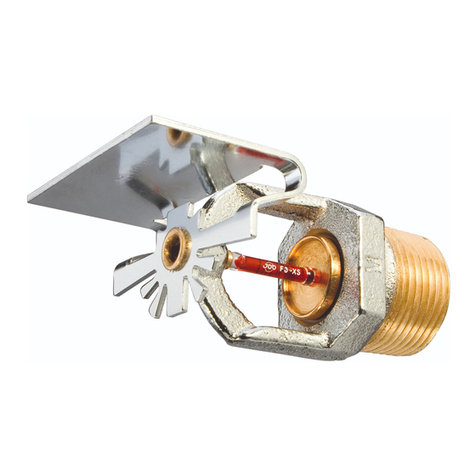
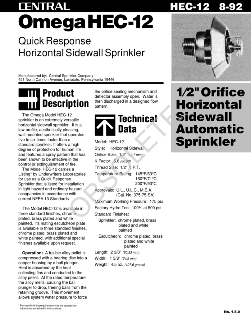
The Central Model S176, 5.6 K-Fac-
tor (1/2 inch orifice), Standard or
Quick Response, Standard Cover-
age, Dry Horizontal Sidewall Sprin-
klers are decorative glass bulb auto-
matic sprinklers designed for use in
applications where the sprinklers
and/or a portion of the connecting
piping may be exposed to freezing
temperatures (e.g., horizontal piping
extensions from a wet pipe sprinkler
system through a wall to protect a
freezer or unheated area of a build-
ing).
The Model S176 Dry Horizontal Side-
wall Sprinklers are available in
standard response (5 mm bulb) or
quick response (3 mm bulb) and in a
wide range of operating tempera-
tures and order lengths. The Model
S176 Sprinklers are intended for use
in fire sprinkler systems designed in
accordance with the standard instal-
lation rules recognized by the appli-
cable Listing or Approval agency
(e.g., UL Listing is based on NFPA
13 requirements).
They are designed for installation
along a wall and just beneath a
smooth ceiling. Installed with their
centerline of waterway horizontal,
these sprinklers produce a quarter-
spherical water distribution pattern
that is predominately directed down-
ward and outward from the sprinkler
with a portion of the spray being di-
rected towards the backwall.
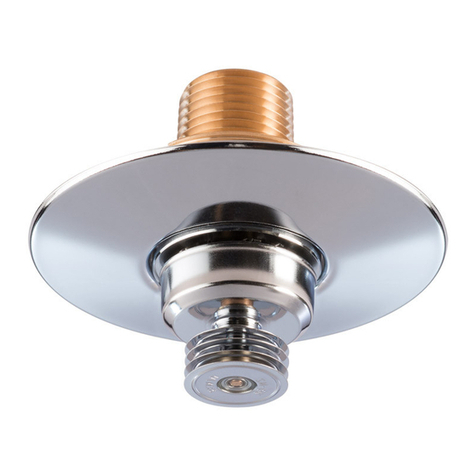
The Standard Escutcheon for the
Model S176 is a separable two-piece
design which allow installation of the
sprinklers and pressure testing of
the fire protection system prior to
wall construction and/or application
of a finish coat to the wall. It also per-
mits refinishing of a wall surface with-
out having to first shut down the fire
protection system and remove the
sprinklers.
Operation: When the Model S176 is
in service, water is prevented from
entering the assembly by the Plug &
O-ring(Ref.Figure2)intheInletof
the Sprinkler. The glass Bulb con-
tains a fluid which expands when ex-
posed to heat. When the rated tem-
perature is reached, the fluid
expands sufficiently to shatter the
glass Bulb, and the Bulb Seat is re-
leased. The compressed Spring is
then able to expand and push the
WaterTubeaswellastheGuide
Tube outward. This action simultane-
ously pulls inward on the Yoke, with-
drawing the Plug & O-ring from the
Inlet, which then allows the sprinkler
to activate and flow water.
WARNINGS
The Model S176 Dry Horizontal Side-
wall Sprinklers described herein
must be installed and maintained in
compliance with this document, as
well as with the applicable standards
of the National Fire Protection Asso-
ciation, in addition to the standards
of any other authorities having juris-
diction. Failure to do so may impair
the integrity of these devices.
The owner is responsible for main-
taining their fire protection system
and devices in proper operating con-
dition. The installing contractor or
sprinkler manufacturer should be
contacted relative to any questions.
The Model S176 Dry Horizontal Side-
wall Sprinklers must only be in-
stalled in fittings that meet the re-
quirements of the Design Criteria
section.
Technical
Data
Sprinkler Identification Number
SIN C3355 (Standard Response)
SIN C3335 (Quick Response)
Approvals
UL and ULC Listed. FM Approved.
(Refer to Table A)
Maximum Working Pressure
175 psi (12,1 bar)
Pipe Thread Connection
1 inch NPT or ISO 7-R1
Discharge Coefficient
K=5.6GPM/psi
1/2
(80,6 LPM/bar1/2)
Temperature Ratings
RefertoTableA
Finishes
Sprinkler: Natural Brass, Chrome
Plated, White Polyester
Escutcheon: White Coated or
Chrome Plated
(Colors other than white are avail-
able on request.)
Physical Characteristics
The Plug and Inlet are brass, and
the O-ring is silicone rubber. The
Casing is galvanized carbon steel.
Standard
Escutcheon
No. 5-6.5
Model S176
Standard or Quick Response
Standard Coverage
Dry Hor. Sidewall Sprinklers
Tyco Fire Products — www.centralsprinkler.com
451 North Cannon Avenue, Lansdale, Pennsylvania 19446
Customer Services/Sales: Tel: (215) 362-0700 / Fax: (215) 362-5385
Technical Services: Tel. (800) 381-9312 / Fax: (800) 791-5500
CENTRAL S176 3-01
OBSOLETE
The Frame is bronze, the Deflector
is brass, and the Compression
Screw is bronze. The Water Tube is
brass, and the Bulb Seat, Spring,
and Yoke are stainless steel. The
Guide Tube sub-assembly is con-
structed of stainless steel and brass.
The two pieces of the three available
Escutcheons are low carbon steel.
Design
Criteria
The Model S176 Dry Sprinklers are
to be installed in the 1 inch NPT out-
let of a malleable iron threaded tee
fitting per ANSI B16.3 or cast iron
threaded tee fitting per ANSI B16.4
with the end sprinkler fitting on a
branch line to be plugged as shown
in Figure 1.
NOTE
Do not install the Model S176 into
any other type fitting without first con-
sulting the Technical Services De-
partment. Failure to use the appropri-
ate fitting may result in: failure of the
sprinkler to properly operate due to
binding of the inlet Plug; or, insuffi-
cient engagement of the inlet pipe
threads with consequent leakage.
When Dry Sprinklers are to be used
in wet pipe sprinkler systems protect-
ing areas subject to freezing tem-
peratures (e.g., coolers or freezers),
consideration must be given to the
appropriate length of the sprinkler
that will prevent freezing of the water
in the connecting pipes, due to con-
duction. When the temperature sur-
rounding the wet pipe sprinkler sys-
tem is maintained at a minimum
Table A
Model S176 Standard and Quick Response
Dry Horizontal Sidewall Sprinkler
Laboratory Listings and Approvals
SPRINKLER FINISH
Temperature
Rating
Bulb
Color Code
Natural
Brass
Chrome
Plated
135°F/57°C
155°F/68°C
175°F/79°C
Red
Yellow
Orange
“A” Order Length:
2-1/2 to 48 inches
(63.5 to 1219.2 mm)
Deflector-to-Ceiling
Distance:
4 to 12 inches
(100 to 300 mm)
See Note 4
1, 2, 3
Notes:
1. Listed by Underwriters Laboratories, Inc. for use in Light or
Ordinary Hazards.
2. Listed by Underwriters’ Laboratories of Canada for use in
Light or Ordinary Hazards.
3. Approved by Factory Mutual Research Corporation for use
in Light or Ordinary Hazards. (FM limits Quick Response
Sprinklers to wet pipe systems.)
4. To meet the requirement of a deflector-to-ceiling distance of
4 to 12 inches, the centerline of the sprinkler waterway
shown in Figure 1 must be 4-5/16 to 12-5/16 inches below
the ceiling.
* Available in Standard Response Only.
1, 2, 3
1, 2, 3
200°F/93°C
286°F/141°C
Green
Blue
1, 2, 3
1, 2, 3
360°F/182°C* Mauve 1, 2
Polyester
(All
Colors)
1, 2
1, 2
1, 2
1, 2
1, 2
1, 2
Figure 1
Model S176 Dry Horizontal Sidewall Sprinkler Installation Dimensions
SPRINKLER FITTING
(REFER TO DESIGN
1" NPT (ISO 7/1 ON SPECIAL REQUEST)
SURFACE
MOUNTING
4" ± 1/8"
(101.6 ± 3.2 mm)
2-1/2" (63.5 mm) MINIMUM
"A" ORDER LENGTH
48" (1.22 m) MAXIMUM
(44.5 mm)
1-3/4" DIA.
FLAT
WRENCH
(WALL)
CRITERIA SECTION)
(76.2 mm)
3" DIA.
3.5°
5/16"
(7.9 mm)
CENTERLINE
OF WATERWAY
SPRINKLER
FITTING
FACE OF
IN 1/4" INCREMENTS
OBSOLETE
temperature of 40°F/4°C, the follow-
ing are the minimum recommended
lengths between the face of the
sprinkler fitting and the outside sur-
face of the protected area (i.e.,
length exposed to minimum ambient
of 40°F/4°C):
•12 inches (300 mm) when the tem-
perature within the protected area is
-20°F/-29°C
•18 inches (450 mm) when the tem-
perature within the protected area is
-40°F/-40°C
•24 inches (600 mm) when the tem-
perature within the protected area is
-60°F/-51°C
For protected area temperatures be-
tween those given above, the mini-
mum recommended length from the
face of the fitting to the outside of
the protected area may be deter-
mined by interpolating between the
indicated values.
NOTE
When Dry Sprinklers penetrate a
wall into an area subject to freezing,
the clearance space around the
Sprinkler Casing must be completely
sealed in order to prevent the leak-
age of moist air into the freezing
area which might result in the forma-
tion of condensate around the
Frame, Deflector, Bulb Seat, or Bulb.
Failure to prevent the formation of
condensate could result in the build-
up of ice around the releasing com-
ponents and, consequently, either
an inadvertent operation of the sprin-
kler or impaired operation due to re-
duced thermal sensitivity.
Installation
The Model S176 must be installed in
accordance with the following instruc-
tions:
NOTES
The Model S176 must only be in-
stalled in fittings that meet the re-
quirements of the Design Criteria
section.
Refer to the Design Criteria section
for other important requirements re-
garding sealing of the clearance
space around the Sprinkler Casing.
Do not install any bulb type sprinkler
if the bulb is cracked or there is a
loss of liquid from the bulb. With the
sprinkler held horizontally, a small
air bubble should be present. The di-
ameter of the air bubble is approxi-
mately 1/16 inch (1,6 mm) for the
135°F/57°C rating to 1/8 inch (3,2
mm) for the 360°F/182°C rating.
A leak tight 1 inch NPT sprinkler
joint should be obtained with a
torque of 20 to 30 ft.lbs. (26,8 to
40,2 Nm). Higher levels of torque
may distort the sprinkler inlet with
consequent leakage or impairment
of the sprinkler.
Do not attempt to compensate for in-
sufficient adjustment in an Escutch-
eon Plate by under- or over-tighten-
ing the Sprinkler. Readjust the
position of the sprinkler fitting to suit.
Step 1. The sprinkler must be in-
stalled only in the horizontal posi-
tion, and the word “TOP” on the de-
flector must face upwards toward the
ceiling.
Step 2. With pipe thread sealant ap-
plied to the pipe threads, hand
Figure 2
Model S176 Dry Horizontal Sidewall Sprinkler Assembly
WATER
TUBE
GUIDE
TUBE HOLEINLET
INSERT DEFLECTOR5mm
SCREW
COMPRESSIO
N
O-RING
PLUG &
BULB
SEAT
YOKE
1" NPT
CASING
SPRING
VENT
FRAME
BULB
Figure 3
W-Type 7 Sprinkler
Wrench
RECESS
WREN
C
H
ENSURE ENGAGEMENT WITH
PUSH WRENCH IN TO
SPRINKLER WREN
C
HIN
G
AREA
Figure 4
Escutcheon Installation
OBSOLETE
tighten the sprinkler into the sprin-
kler fitting.
Step 3. Wrench tighten the sprinkler
by wrenching on the Casing with a
pipe wrench whenever the casing is
readily accessible. Otherwise, use a
W-Type 7 Sprinkler Wrench (Ref. Fig-
ure 3). The wrench recess of the W-
Type7istobeappliedtothesprin-
kler wrench flats (Ref. Figure 1).
Step 4. After the wall construction is
completed or the finish coat has
been applied to the wall (as applica-
ble), slide on the outer piece of the
Escutcheon until it comes in contact
with the wall (Ref Figure 4)
Care &
Maintenance
The Model S176 must be maintained
and serviced in accordance with the
following instructions:
NOTES
Absence of the outer piece of an es-
cutcheon, which is used to cover a
clearance hole, may delay the time
to sprinkler operation in a fire situ-
ation.
Before closing a fire protection sys-
tem main control valve for mainte-
nance work on the fire protection sys-
tem which it controls, permission to
shut down the affected fire protec-
tion systems must be obtained from
the proper authorities and all person-
nel who may be affected by this ac-
tion must be notified.
A Vent Hole is provided in the Bulb
Seat (Ref. Figure 2) to indicate if the
Dry Sprinkler is remaining dry. Evi-
dence of leakage from the Vent Hole
is an indication that there may be
weepage past the O-ring seal and,
therefore, it is an indication that the
sprinkler needs to be removed for de-
termining the cause of leakage (e.g.
an improper installation or an ice
plug). The fire protection system con-
trol valve must be closed and the
system drained before removing the
sprinkler.
Sprinklers which are found to be
leaking or exhibiting visible signs of
corrosion must be replaced.
Automatic sprinklers must never be
shipped or stored where their tem-
perature will exceed 100°F/38°C and
they must never be painted, plated,
coated, or otherwise altered after
leaving the factory. Modified sprin-
klers must be replaced. Sprinklers
that have been exposed to corrosive
products of combustion, but have not
operated, should be completely
cleaned by wiping the sprinkler with
a cloth or by brushing it with a soft
bristle brush.
Care must be exercised to avoid
damage - before, during, and after
installation. Sprinklers damaged by
dropping, striking, wrench twist/slip-
page, or the like, must be replaced.
Also, replace any sprinkler that has
a cracked bulb or that has lost liquid
from its bulb (Ref. Installation Sec-
tion).
The owner is responsible for the in-
spection, testing, and maintenance
of their fire protection system and de-
vices in compliance with this docu-
ment, as well as with the applicable
standards of the National Fire Protec-
tion Association (e.g., NFPA 25), in
addition to the standards of any
other authorities having jurisdiction.
The installing contractor or sprinkler
manufacturer should be contacted
relative to any questions.
It is recommended that automatic
sprinkler systems be inspected,
tested, and maintained by a qualified
Inspection Service.
Limited
Warranty
Products manufactured by Tyco Fire
Products are warranted solely to the
original Buyer for ten (10) years
against defects in material and work-
manship when paid for and properly
installed and maintained under nor-
mal use and service. This warranty
will expire ten (10) years from date
of shipment by Tyco Fire Products.
No warranty is given for products or
components manufactured by com-
panies not affiliated by ownership
with Tyco Fire Products or for prod-
ucts and components which have
been subject to misuse, improper in-
stallation, corrosion, or which have
not been installed, maintained, modi-
fied or repaired in accordance with
applicable Standards of the National
Fire Protection Association, and/or
the standards of any other Authori-
ties Having Jurisdiction. Materials
found by Tyco Fire Products to be de-
fective shall be either repaired or re-
placed, at Tyco Fire Products’ sole
option. Tyco Fire Products neither as-
sumes, nor authorizes any person to
assume for it, any other obligation in
connection with the sale of products
or parts of products. Tyco Fire Prod-
ucts shall not be responsible for
sprinkler system design errors or in-
accurate or incomplete information
supplied by Buyer or Buyer’s repre-
sentatives.
IN NO EVENT SHALL TYCO FIRE
PRODUCTS BE LIABLE, IN CON-
TRACT, TORT, STRICT LIABILITY
OR UNDER ANY OTHER LEGAL
THEORY, FOR INCIDENTAL, INDI-
RECT, SPECIAL OR CONSEQUEN-
TIAL DAMAGES, INCLUDING BUT
NOT LIMITED TO LABOR
CHARGES, REGARDLESS OF
WHETHER TYCO FIRE PRODUCTS
WAS INFORMED ABOUT THE POS-
SIBILITY OF SUCH DAMAGES,
ANDINNOEVENTSHALLTYCO
FIRE PRODUCTS’ LIABILITY EX-
CEED AN AMOUNT EQUAL TO THE
SALES PRICE.
THE FOREGOING WARRANTY IS
MADE IN LIEU OF ANY AND ALL
OTHER WARRANTIES EXPRESS
OR IMPLIED, INCLUDING WAR-
RANTIES OF MERCHANTABILITY
AND FITNESS FOR A PARTICU-
LAR PURPOSE.
Ordering
Information
Ordering Information:
1. When placing an order, indicate
the full product name. Please include
the quantity, model, response charac-
teristic, temperature rating, finish,
and order length.
Dry Sprinklers are furnished based
upon Order Length as measured
from the face of the wall to the face
of the sprinkler fitting in which the in-
dividual sprinkler is to be installed.
After the measurement is taken,
round it to the nearest 1/4 inch incre-
ment.
2. W-Type 7 Sprinkler Wrench.
Patents:
U.S.A. Patent Number 5,188,185 is
applicable to the Model S176 Dry
Horizontal Sidewall Sprinklers.
Printed in U.S.A. 3-01
OBSOLETE

Other Tyco Fire Product Irrigation System manuals

Tyco Fire Product CENTRAL TY-B User manual

Tyco Fire Product

Tyco Fire Product CENTRAL TY-B User manual

Tyco Fire Product Star Galaxy SG User manual

Tyco Fire Product

Tyco Fire Product Star Galaxy SG User manual

Tyco Fire Product Gem RFII Series User manual

Tyco Fire Product

Tyco Fire Product Gem RFII Series User manual

Tyco Fire Product CENTRAL K25-1 User manual

Tyco Fire Product

Tyco Fire Product CENTRAL K25-1 User manual

Tyco Fire Product Gem F978 User manual

Tyco Fire Product

Tyco Fire Product Gem F978 User manual

Tyco Fire Product CENTRAL K17-231 User manual

Tyco Fire Product

Tyco Fire Product CENTRAL K17-231 User manual

Tyco Fire Product Gem F898 User manual

Tyco Fire Product

Tyco Fire Product Gem F898 User manual

Tyco Fire Product Gem F960/Q-48 User manual

Tyco Fire Product

Tyco Fire Product Gem F960/Q-48 User manual

Tyco Fire Product Star SuperNova S124 User manual

Tyco Fire Product

Tyco Fire Product Star SuperNova S124 User manual

Tyco Fire Product Star Luminous S170 User manual

Tyco Fire Product

Tyco Fire Product Star Luminous S170 User manual

Tyco Fire Product CENTRAL GB-LO 17/32 User manual

Tyco Fire Product

Tyco Fire Product CENTRAL GB-LO 17/32 User manual

Tyco Fire Product CENTRAL GB User manual

Tyco Fire Product

Tyco Fire Product CENTRAL GB User manual

Tyco Fire Product CENTRAL BVR User manual

Tyco Fire Product

Tyco Fire Product CENTRAL BVR User manual

Tyco Fire Product Gem STAINLESS STEEL QUARTZOID User manual

Tyco Fire Product

Tyco Fire Product Gem STAINLESS STEEL QUARTZOID User manual

Tyco Fire Product Star SG-R User manual

Tyco Fire Product

Tyco Fire Product Star SG-R User manual

Tyco Fire Product RFII Series User manual

Tyco Fire Product

Tyco Fire Product RFII Series User manual

Tyco Fire Product CENTRAL A-1 User manual

Tyco Fire Product

Tyco Fire Product CENTRAL A-1 User manual

Tyco Fire Product TY-QRF User manual

Tyco Fire Product

Tyco Fire Product TY-QRF User manual

Tyco Fire Product STAR SIN S3400 SR User manual

Tyco Fire Product

Tyco Fire Product STAR SIN S3400 SR User manual

Tyco Fire Product CENTRAL A User manual

Tyco Fire Product

Tyco Fire Product CENTRAL A User manual

Tyco Fire Product CENTRAL GB-20 User manual

Tyco Fire Product

Tyco Fire Product CENTRAL GB-20 User manual

Tyco Fire Product Star StarMax S100 User manual

Tyco Fire Product

Tyco Fire Product Star StarMax S100 User manual

Tyco Fire Product Gem F960 User manual

Tyco Fire Product

Tyco Fire Product Gem F960 User manual

Tyco Fire Product SIN S2983 User manual

Tyco Fire Product

Tyco Fire Product SIN S2983 User manual

Popular Irrigation System manuals by other brands

Viking MICROFAST VK352 Technical data

Viking

Viking MICROFAST VK352 Technical data

Senju Sprinkler RC-QR manual

Senju Sprinkler

Senju Sprinkler RC-QR manual

Viking FREEDOM VK470 Technical data

Viking

Viking FREEDOM VK470 Technical data

Reliable F156 Series Bulletin

Reliable

Reliable F156 Series Bulletin

Tyco DS-2 Series manual

Tyco

Tyco DS-2 Series manual

Seametrics EX90 quick start guide

Seametrics

Seametrics EX90 quick start guide

Viking VK950 manual

Viking

Viking VK950 manual

Viking FREEDOM VK466 Technical data

Viking

Viking FREEDOM VK466 Technical data

Johnson Controls Tyco EC-8 Series manual

Johnson Controls

Johnson Controls Tyco EC-8 Series manual

Gardena OS 140 operating instructions

Gardena

Gardena OS 140 operating instructions

General Air Products Vapor Pipe Shield VPS-500A Installation, operation and maintenance manual

General Air Products

General Air Products Vapor Pipe Shield VPS-500A Installation, operation and maintenance manual

Tyco ESFR-17 manual

Tyco

Tyco ESFR-17 manual

Toro 53763 Installation and operating instructions

Toro

Toro 53763 Installation and operating instructions

Reliable LT56 Series manual

Reliable

Reliable LT56 Series manual

Tyco Ultra K34 Operation

Tyco

Tyco Ultra K34 Operation

Hunter PRO-C Hydrawise Software/App Owner's Manual

Hunter

Hunter PRO-C Hydrawise Software/App Owner's Manual

Eden 94120-EDAMZ manual

Eden

Eden 94120-EDAMZ manual

SNOWJOE Aquajoe AJ-OMS18-TRB manual

SNOWJOE

SNOWJOE Aquajoe AJ-OMS18-TRB manual

manuals.online logo
manuals.online logoBrands
  • About & Mission
  • Contact us
  • Privacy Policy
  • Terms and Conditions

Copyright 2025 Manuals.Online. All Rights Reserved.