TFP461
Page 2 of 6
Operation
When the TYCO Series LFII Dry Type
Residential Horizontal Sidewall Sprin-
kler is in service, water is prevented
from entering the assembly by the Plug
with Sealing Assembly (see Figure 1) in
the Inlet of the Sprinkler.
The glass Bulb contains a fluid that
expands when exposed to heat. When
the rated temperature is reached, the
fluid expands sufficiently to shatter the
glass Bulb to release the Bulb Seat. The
system’s water pressure is then able to
unseat the Plug with Sealing Assem-
bly. The Plug Spring turns the Plug with
Sealing Assembly aside, allowing the
sprinkler to activate and flow water.
Design
Criteria
The TYCO Series LFII Dry Type Resi-
dential Horizontal Sidewall Sprinklers
(TY2335) are UL and C-UL Listed for
installation in accordance with this
section.
Residential Sprinkler Design Guide
When conditions exist that are outside
the scope of the criteria provided in
this section, refer to the technical data
sheet entitled Residential Sprinkler
Design Guide (TFP490) for the manu-
facturer’s recommendations that may
be acceptable to the local authority
having jurisdiction.
System Type
Wet Pipe
Hydraulic Design
(NFPA 13D and 13R)
For systems designed to NFPA 13D or
NFPA 13R, the minimum required sprin-
kler flow rates are given in Table A as a
function of temperature rating and the
maximum allowable coverage areas.
The sprinkler flow rate is the minimum
required discharge from each of the
total number of design sprinklers, as
specified in NFPA 13D or NFPA 13R.
Hydraulic Design
(NFPA 13)
For systems designed to NFPA 13, the
number of required design sprinklers is
the four most hydraulically demanding
sprinklers. The minimum required dis-
charge from each of the four sprinklers
is the greater of the following:
•
ow rates listed in Table A as a
function of temperature rating and
the maximum allowable coverage
area.
•
minimum discharge of 0.1 gpm/ft²
over the design area comprised
of the four most hydraulically
demanding sprinklers for the actual
coverage areas protected by four
sprinklers.
Obstruction to Water Distribution
Sprinklers are to be located in accor-
dance with the obstruction rules of
NFPA 13D, 13R, and 13 as applicable
for residential sprinklers as well as with
the obstruction criteria described within
the Technical Data Sheet TFP490.
Operational Sensitivity
The sprinkler must be located relative
to the mounting surface as shown in
Figures 2 and 3.
Sprinkler Spacing
The minimum lateral spacing between
sprinklers is 8 ft (2,4 m). The maximum
lateral spacing between sprinklers
cannot exceed the length of the cov-
erage area (see Table A) hydraulically
calculated (for example, a maximum of
12 ft for a 12 ft x 12 ft coverage area or
18 ft for a 18 ft x 20 ft coverage area.)
Sprinkler Fittings
The following fittings may be used:
•
the 1 in. NPT outlet or run of a
malleable or ductile iron threaded
tee ttings that meet the dimen-
sional requirements of ANSI B16.3
(Class 150)
•
the 1 in. NPT outlet or run of a cast
iron threaded tee tting that meet
the dimensional requirements of
ANSI B16.4 (Class 125)
Technical
Data
Approvals
UL and C-UL Listed
Certified to all requirements of
NSF/ANSI 61
Note: Sprinklers with a polyester finish are
UL and C-UL Listed as corrosion-resistant
sprinklers.
See the Design Criteria section for details
on these approvals.
Maximum Working Pressure
175 psi (12,1 bar)
Discharge Coefficient
K=4.4 GPM/psi½(63,4 LPM/bar½)
Inlet Thread Connections
1 in. NPT
ISO 7-R 1
Sprinkler Temperature Rating
155°F (68°C)
Finishes
Natural Brass, Signal White Polyester
Coated, or Chrome Plated
Order Lengths
Minimum: 3-3/4 in. (95,3 mm)
Maximum: 24 in. (609,6 mm)
Physical Characteristics
Inlet . . . . . . . . . . . . . . . . . . . . . . . . . . . . . . Brass
Plug . . . . . . . . . . . . . . . . . . . . . . . . . . . . . Brass
Yoke....................... Stainless Steel
Casing ....................Galvanized Steel
Insert . . . . . . . . . . . . . . . . . . . . . . . . . . . Bronze
Bulb Seat. . . . . . . . . . . . . . . . . . . Stainless Steel
Bulb . . . . . . . . . . . . . . . . . . . . . . . . . . . . . . . Glass
Compression Screw . . . . . . . . . . . . . . . . . .Brass
Deflector . . . . . . . . . . . . . . . . . . . . . . . . . . Brass
Frame . . . . . . . . . . . . . . . . . . . . . . . . . . . . .Brass
Guide Tube . . . . . . . . . . . . . . . . . Stainless Steel
Water Tube . . . . . . . . . . . . . . . . . Stainless Steel
Bushing . . . . . . . . . . . . . . . . . . . . . . . . . . . .Brass
Plug Spring . . . . . . . . . . . . . . . . . Stainless Steel
Sealing Assembly ..Beryllium Nickel w/TEFLON
Escutcheon . . . . . . . . . . . . . . . . . . .Carbon Steel
TUBE
VENT
HOLE
TUBE
BULB
SEAT
SCREW
BULB
INLET
BAND
SPRING
ESCUTCHEON
MOUNTING PLATE
INLET
YOKE
CASINGBUSHING
FRAMEPLUG WITH
SEALING
ASSEMBLY
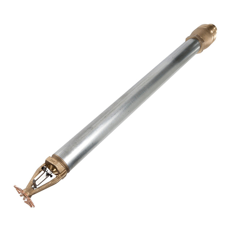
FIGURE 1
SERIES LFII DRY TYPE
RESIDENTIAL HORIZONTAL SIDEWALL SPRINKLERS (TY2335) ASSEMBLY
