Tyco Grinnell F692 DESIGNER User manual

CONCEALED PENDENT SPRINKLER with 1/2" ADJUSTMENT
MODEL F692 DESIGNER
STANDARD RESPONSE, 4 mm BULB TYPE, 1/2" ORIFICE, 1/2" NPT
GENERAL DESCRIPTION
The 1/2 inch (15 mm) orifice Model
F692, Standard Response Designer
Concealed Pendent Sprinklers (Ref.
Figure A) are pendent automaticsprin-
klers of the frangible bulb type. They
are “standard response - standard ori-
fice spray sprinklers” intended for use
in fire sprinkler systems designed in
accordance with the standard installa-
tion rules recognized by the applicable
Listing or Approval agency (e.g. UL
Listing is based on NFPA 13 require-
ments). The F692 produces a hemi-
spherical water distribution pattern be-
low the deflector. Each unit includes a
Cover Plate Assembly which conceals
the sprinkler operating components
above the ceiling.
The small Cover Plate is flat with a low
profile which blends in with the ceiling
for an aesthetically pleasing appear-
ance. Standard finishes for the Cover
Plate are satin chrome plated and
painted white. Other factory applied
paintedfinishes fortheCoverPlateare
available on special order.
The separable two-piece design of the
Cover Plate and Mounting Cup As-
semblies allows installation of the
sprinklers and pressure testing of the
fire protection system prior to installa-
tion of a suspended ceiling or applica-
tion of the finish coating to a fixed
ceiling.The separable designalso per-
mits removal of suspended ceiling
panels for access to building service
equipment, without having to first shut
down the fire protection system and
remove sprinklers.
Also, the separable two-piece design
of the the F692 Concealed Sprinkler
provides for 1/2 inch of vertical adjust-
ment, to reduce the accuracy to which
the length of fixed pipe drops to the
sprinklers must be cut.
Each sprinkler is shipped with a dam-
age resistant Protective Cap, which
can be temporarily left in place until
installation of the ceiling is complete.
APPROVALS AND STANDARDS
The1/2 inchorifice Model F692Stand-
ard Response Concealed Pendent
Sprinklers are listed by Underwriters
Laboratories Inc. and listed by Under-
writers Laboratories Inc. for use in
Canada (i.e., C-UL Listed).
The1/2 inchorifice Model F692Stand-
ard Response Concealed Pendent
SprinklersareapprovedbyFactory
Mutual Research Corporation for use
in Hazard Occupancies up to and in-
cluding Ordinary, Group II. The Ordi-
nary Hazard Occupancy approval is
limited to use in wet pipe systems and
preaction systems qualifying as wet
pipe systems.
The laboratory listings and approvals
apply to the temperature ratings and
Cover Plate finishes indicated in Fig-
ure A. WARNING
The Model F692 Standard Response
Concealed Pendent Sprinklers de-
Printed in U.S.A. 6-98 TD579Q
TEMPERATURE RATINGS:
135°F / 57°C
155°F / 68°C
175°F / 79°C
200°F / 93°C
K-FACTOR (NOMINAL):
5.6 ( GPM ÷psi1/2)
80.6 ( LPM ÷bar1/2)
ADJUSTMENT:
1/2 INCH (12.7mm)
COVER PLATE FINISHES:
CHROME PLATED
WHITE PAINTED
SPECIAL COLOR PAINTED
Dim. Inches MM
A- 3-5/16 84,1
B- 3/16 4,8
C- 2-5/8 66,8
D-Min. 1-13/16 46,0
D-Nom. 2-1/16 52,4
D-Max. 2-5/16 58,7
FIGURE A
MODEL F692 STANDARD RESPONSE CONCEALED PENDENT SPRINKLER
OBSOLETE

scribed herein must be installed and
maintained in compliance with this
document, as well as with the appli-
cable standards of the National Fire
Protection Association, in addition to
the standards of any other authorities
having jurisdiction. Failure to do so
may impair the integrity of these de-
vices.
The F692 Standard Response Con-
cealedPendentSprinklersmustnotbe
used in applications where the air
pressure above the ceiling is greater
than that below. Downdrafts through
the Mounting Cup could delay sprin-
kler operation in a fire situation.
The owner is responsible for main-
taining their fire protection system
and devices in proper operating con-
dition. The installing contractor or
manufacturer should be contacted
relative to any questions.
TECHNICAL DATA
The 1/2 inch (15 mm) orifice Model
F692 Standard Response Concealed
Pendent Sprinklers are rated for use at
a maximum service pressure of 175
psi (12,1 bar). The available tempera-
ture ratings and nominal installation
dimensions are given in Figure A. Ta-
ble 1 summarizes the maximum per-
missible ceiling temperatures for use
with the F692.
Standard finishes for the Cover Plate
are satin chrome and painted white;
however, other factory painted finishes
for the Cover Plate are available on
special order.
The nominal discharge curves plotted
in Figure C represents the flow “Q” in
GPM (LPM) as determined by the for-
mula:
where the nominal sprinkler discharge
coefficient “K” = 5.6 (80,7); and “p” =
the residual flowing pressure in psi
(bar). Listing standards permit the ac-
tual value of “K” to vary from 5.3 to 5.8
(76,4 to 83,6); however for hydraulic
calculations, a K-factor of 5.6 (80,7) is
to be applied.
The F692 Sprinkler consists of two
sub-assemblies, as shown in Figure B:
the Sprinkler/Mounting Cup Assembly
and the Cover Plate Assembly.
Sprinkler/Mounting Cup Assembly
The Sprinkler Assembly utilizes a 4
mm Bulb and has a die-cast dezincifi-
cation resistant (DZR) bronze alloy
Frame. The two pieces of the Button
Assembly are constructed from brass
per ASTM B16 (C36000) and copper
(C12200). The Gasketed Spring Plate
consists of an Beryllium Nickel
(N03360) disc spring that is sealed on
both its inside and outside edges with
aTeflon†gasket. The Compression
Screw is brass per ASTM B16
(C36000). The Deflector is bronze per
ASTM B36 (C22000), the Arms are
phosphor bronze per CDA Alloy 510.
The Mounting Cup is chrome plated
low carbon sheet steel.
The Mounting Cup Assembly is pro-
vided with a Protective Cap (Ref. Fig-
ure E), which helps prevent damage to
the Deflector and Arms before the
Cover Plate Assembly is installed.The
Protective Cap is designed such that
the Cap can be opened to expose the
sprinkler for temporary fire protection,
until the ceiling installation is com-
pleted and the Cover Plate can be in-
stalled. The Protective Cap is dis-
cardedoncetheCoverPlateAssembly
is installed.
Cover Plate Assembly
The Cover Plate Assembly, which
screws onto the Sprinkler/Mounting
Cup Assembly, consists of a Cover
Plate which is soldered to an Enclo-
sure at three equidistant locations
around their peripheries. The Cover
Plate and Enclosure are brass per
ASTM B36 (C26000 or C26800). A
QKp
=
SPRINKLER
TEMPERATURE
RATING
COVER PLATE
TEMPERATURE
RATING
MAXIMUM
CEILING
TEMPERATURE
135°F / 57°C
200°F / 93°C
135°F / 57°C
135°F / 57°C 100°F / 38°C
100°F / 38°C
TABLE 1
SUMMARY OF MAXIMUM PERMITTED CEILING TEMPERATURE RATINGS
155°F / 68°C
175°F / 79°C 165°F / 74°C
165°F / 74°C 150°F / 68°C
150°F / 68°C
FIGURE B
MODEL F692 STANDARD RESPONSE
CONCEALED PENDENT SPRINKLER ASSEMBLY
†DuPont Registered Trademark
OBSOLETE

Type 302 stainless steel compression
Spring is locatedbetweentheflangeof
the Enclosure and the Cover Plate, to
ensure separation of the two pieces
when the solder melts.
Solder having a temperature rating of
135°F/57°C is used with Cover Plate
Assemblies for the 135°F/57°C and
155°F/68°Csprinklers,and solderwith
a temperature rating of 165°F/74°C is
used with Cover Plate Assemblies for
the 175°F/79°C and 200F/93C sprin-
klers (Ref. Table 1). When the Cover
Plate Assembly is exposed to a tem-
perature sufficient to fuse the solder,
the Cover Plate will fall away from the
Enclosure which allows the Deflector
to drop into position and, to expose the
Sprinkler for operation.
Alabel locatedonthesideoftheCover
Plate Assembly indicates the tempera-
ture rating of the Cover Plate Assem-
blyandthetemperatureratingofthe
F692Sprinklerwithwhichitistobe
used.
INSTALLATION
NOTES
Do not install any bulb type sprinkler
if the bulb is cracked or there is a loss
ofliquidfromthebulb.Withthesprin-
kler held horizontally, a small air
bubble should be present. The diame-
teroftheairbubblevariesfromap-
proximately1/16inch(1,6mm)for
the 135°F/57°C rating to 3/32 inch
2,4 mm) for the 200° F/93°C rating.
Only use the Model 2111 Sprinkler
Wrench for installation of the F692
Sprinkler. Do not wrench on the
Sprinkler other than as shown in Fig-
ure D.
Do not attempt to make-up for insuf-
ficient adjustment in the Sprinkler
Assembly by under- or over-tightening
the Sprinkler/Mounting Cup Assem-
bly. Readjust the position of the sprin-
kler fitting to suit.
A leak tight 1/2 inch NPT sprinkler
joint should be obtainedwith a torque
of 7 to 14 ft.lbs.(9,5 to 19,0 Nm).More
than 21 ft. lbs. (28,5 Nm) of torque
may distort the sprinkler orifice seat
with consequent leakage.
Proceed with the installation as fol-
lows:
1. The pipe connected to the sprinkler
fitting should be cut so that the bot-
tom face of the fitting is between
1-15/16 and 2-3/16 inch (49,2 mm
and 55,6 mm) abovethe ceiling line.
By using a 1/4 inch (6,4 mm) range
for the “D” dimension, the remaining
1/4 inch (6,4 mm) of adjustment can
be used to compensate for the pos-
sible manufacturing variations in the
make-in of the sprinklers and the
take-out of fittings (as permitted by
ANSI B1.20.1).
FIGURE C
NOMINAL DISCHARGE CURVES
FIGURE D
MODEL 2111 SPRINKLER WRENCH
FIGURE E
PROTECTIVE CAP
OBSOLETE

2. Remove the Protective Cap.
3. With pipe thread sealant applied to
the pipe threads, and using the
Model 2111 Wrench positioned as
showninFigureD,install andtighten
the F692 Sprinkler/Mounting Cup
Assembly into the fitting. The 2111
will accept a 1-1/16 inch hex socket
or a 1/2 inch ratchet drive.
4. Refer to Figure E and replace the
Protective Cap by pushing it up-
wardsuntilitbottoms out against the
Mounting Cup. The Protective Cap
helps prevent damage to the Deflec-
tor and Arms during ceiling installa-
tion and/or during application of the
finish coating of the ceiling. It may
also be used to locate the center of
theclearance holebygentlypushing
the ceiling material up against the
center point of the Cap.
Open the Protective Cap as shown
in Figure E, if the fire protection sys-
tem is to be in service while the
ceiling installation is being com-
pleted.
5. After theceilinghasbeencompleted
withthe2-5/8inch (66,7mm)diame-
ter clearance hole, remove and dis-
card the Protective Cap, and verify
that the Deflector moves up and
down freely.
If the F692 Sprinkler has been dam-
aged and the Deflector does not
move up and down freely, replace
the entire F692 Sprinkler assembly.
Do not attempt to modify or repair a
damaged sprinkler.
6. Screw-on the Cover Plate Assembly
until its flange just comes in contact
with the ceiling.
Do not continue to screw-on the
Cover Plate Assembly such that it
lifts a ceiling panel out of its normal
position.
If the Cover Plate Assembly cannot
be engaged with the Mounting Cup
or the Cover Plate Assembly cannot
be engaged sufficiently to contact
the ceiling, the Sprinkler has been
positioned incorrectly and must be
repositionedaccording toStepNo.1.
CARE AND MAINTENANCE
Automatic sprinklers must never be
shippedorstoredwheretheirtempera-
ture will exceed 100°F/38°C and they
must never be painted, plated, coated
or otherwise altered after leaving the
factory.Modified sprinklers must be re-
placed. Sprinklers that have been ex-
posed to corrosive products of com-
bustion, but have not operated, should
be replaced if they cannot be com-
pletely cleaned by wiping the sprinkler
with a cloth or by brushing it with asoft
bristle brush.
Care must be exercised to avoid dam-
age to the sprinklers - both before and
after installation. Sprinklers damaged
by dropping, striking, wrench
twist/slippage, or the like, must be re-
placed.Also, replace any sprinkler that
has a cracked bulb or that has lost
liquid from its bulb. (Ref. Installation
Section).
If a sprinkler must be removed for
some reason, do not reinstall it or a
replacement without reinstalling the
Cover Plate Assembly.If a Cover Plate
Assembly becomes dislodged during
service, replace it immediately.
NOTES
1. Absence of the Cover Plate Assem-
bly may delay sprinkler operation
in a fire situation.
2. When properly installed, there is a
nominal 3/32 inch (2,4 mm) air
gap between the lip of the Cover
Plate and the ceiling, as shown in
Figure A. This air gap is necessary
for proper operation of the sprin-
kler. If the ceiling is to be repainted
after the installation of the F692,
care must be exercised to ensure
that the new paint does NOT seal
off any of the air gap
3. Factory painted Cover Plates
MUST NOT be repainted. They
should be replaced, if necessary, by
factory painted units.
4. Do not pull the Cover Plate relative
to the Enclosure. Separation may
result.
5. Before closing a fire protection sys-
tem main control valve for mainte-
nance work on the fire protection
system which it controls, permis-
sion to shut down the affected fire
protection system must be obtained
from the proper authorities and all
personnel who may be affected by
this action must be notified.
It is recommended that automatic
sprinkler systems be inspected quar-
terly by a qualified Inspection Service.
WARRANTY
Seller warrants for a period of one year
from the date of shipment (warranty
period) that the products furnished
hereunder will be free from defects in
material and workmanship.
For further details on Warranty, see
Price List.
ORDERING PROCEDURE
Sprinkler Assemblies:
Specify: 1/2 inch orifice, (specify tem-
perature rating), Model F692Standard
Response Concealed Pendent Sprin-
kler with (specify type finish) Cover
Plate, PSN (specify from Table 2).
Contact your local distributor for avail-
ability.
Product Symbol Numbers are not
specified when ordering F692 Sprin-
klers with a special painted finish for
the Cover Plate. It is suggested that a
color chip be provided when ordering
specialpaintedfinishes.Otherwise,re-
sponsibility for duplication of the de-
sired finish cannot be accepted.
Separately Ordered Parts:
Specify: Model 2111 Sprinkler
Wrench, PSN 56-000-2-111.
Replacement Parts:
Specify: (description) for use with
F692 Sprinklers, PSN (specify).
Sprinkler/Mounting Cup Assemblies
arenotavailableasreplacementparts.
Painted White
135°F/57C Cover Plate Assembly
for 135°F/57°C or 155°F/68°C Sprinklers
. . . . . . . . . . . . . . . . . . . . . . PSN 56-690-0-155
Painted White
165°F/74C Cover Plate Assembly
for 175°F/ 79°C or 200°F/93°C Sprinklers
. . . . . . . . . . . . . . . . . . . . . . PSN 56-690-0-200
Chrome Plated
135°F/57C Cover Plate Assembly
for 135°F/57°C or 155°F/68°C Sprinklers
. . . . . . . . . . . . . . . . . . . . . . PSN 56-690-9-155
Chrome Plated
165°F/74C Cover Plate Assembly
for 175°F/ 79°C or 200°F/93°C Sprinklers
. . . . . . . . . . . . . . . . . . . . . . PSN 56-690-9-200
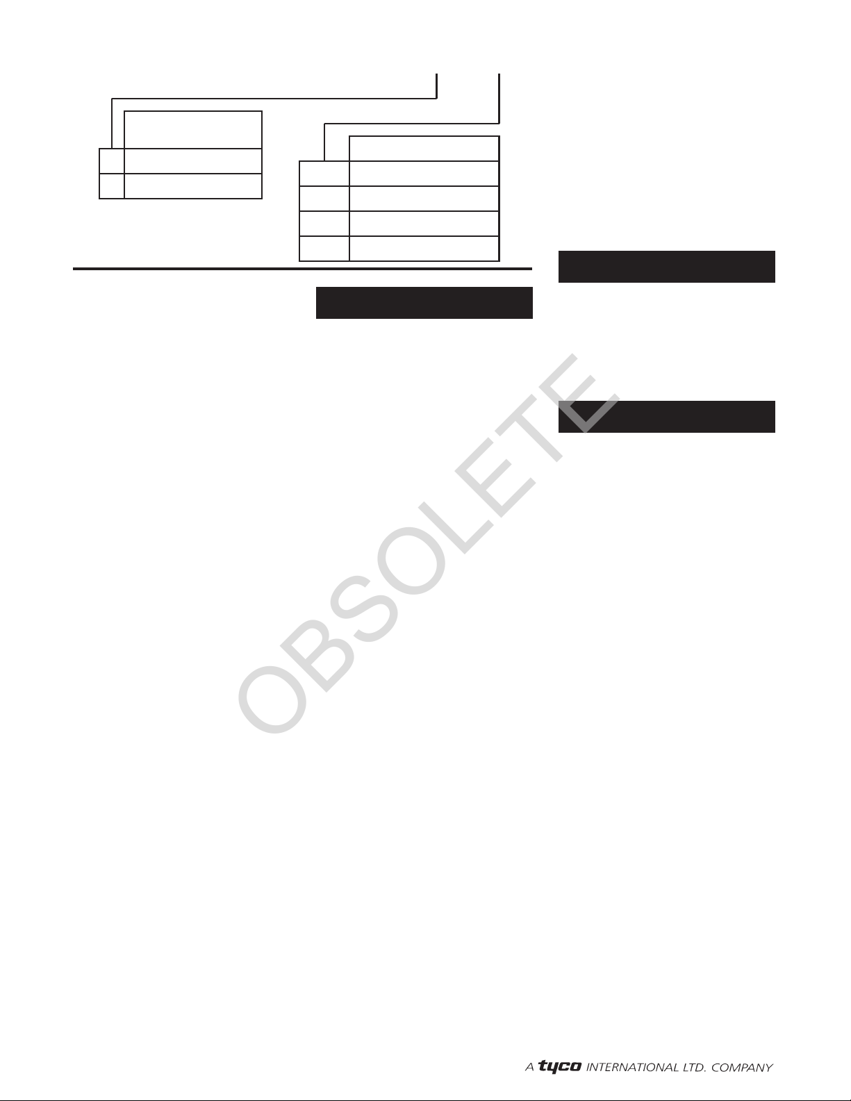
PSN51 -692-X- XXX
9
0
COVER PLATE
FINISH
Chrome Plated
Painted White 155
TEMPERATURE RATING
155°F/68°C
TABLE 2
PRODUCT SYMBOL NUMBER
SELECTION 200 200°F/93°C
135°F/57°C
175°F/79°C175
135
® Reg.trademark of GRINNELL CORPORATION, 3 TYCO PARK, EXETER, NH 03833
OBSOLETE

OBSOLETE
Table of contents
Other Tyco Irrigation System manuals

Tyco
Tyco ELO-231 Series User manual

Tyco
Tyco RFII Series User manual

Tyco
Tyco ESFR-25 Operating and maintenance instructions

Tyco
Tyco EC-8 Series User manual

Tyco
Tyco AquaMist AM4 User manual

Tyco
Tyco TY-B Series User manual

Tyco
Tyco ELOC User manual

Tyco
Tyco CCU Rack Installation guide

Tyco
Tyco CC3 User manual

Tyco
Tyco ESFR-17 User manual

Tyco
Tyco EC-8C User manual

Tyco
Tyco RFII Series User manual

Tyco
Tyco Power Pro Series User manual

Tyco
Tyco Style 60 User manual

Tyco
Tyco Ultra K17 User manual

Tyco
Tyco FTR-1 User manual

Tyco
Tyco ESFR-17 User manual

Tyco
Tyco SW-20 User manual

Tyco
Tyco RapidResponse SIN TY4334 Instruction Manual

Tyco
Tyco RSV-1 User manual