Tyco RapidResponse SIN TY4334 Instruction Manual

Series LFII Residential, NFPA13 Optimized
Horizontal Sidewall Sprinklers
5.8 K-factor
Technical Services: Tel: (800) 381-9312 / Fax: (800) 791-5500
Page 1 of 6 FEBRUARY, 2008 TFP417
IMPORTANT
Always refer to Technical Data
Sheet TFP700 for the “INSTALLER
WARNING” that provides cautions
with respect to handling and instal-
lation of sprinkler systems and com-
ponents. Improper handling and in-
stallation can permanently damage
a sprinkler system or its components
and cause the sprinkler to fail to
operate in a fire situation or cause it
to operate prematurely.
tal adjustment from the flush mounting
surface position. The adjustment pro-
vided by the Recessed Escutcheon re-
duces the accuracy to which the pipe
nipples to the sprinklers must be cut.
The Series LFII (TY4334) has been de-
signed with heat sensitivity and water
distribution characteristics proven to
help in the control of residential fires
and to improve the chance for occu-
pants to escape or be evacuated.
WARNINGS
The Series LFII (TY4334) Residen-
tial Horizontal Sidewall Sprinklers de-
scribed herein must be installed and
maintained in compliance with this
document, as well as with the applica-
ble standards of the National Fire Pro-
tection Association, in addition to the
standards of any other authorities hav-
ing jurisdiction. Failure to do so may
impair the performance of these
devices.
The owner is responsible for maintain-
ing their fire protection system and de-
vices in proper operating condition.
The installing contractor or sprinkler
manufacturer should be contacted
with any questions.
Sprinkler/ Model
Identification
Number
SIN TY4334
General
Description
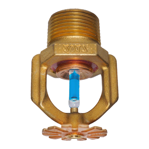
The Tyco®Rapid Response™Series
LFII (TY4334) Residential Horizontal
Sidewall Sprinklers are decorative, fast
response, frangible bulb sprinklers de-
signed for use in residential occupan-
cies such as homes, apartments, dor-
mitories, and hotels. When enhanced
flow characteristics for residential por-
tions of any occupancy per NFPA 13 is
the major consideration, the Series LFII
(TY4334) should be the first choice.
When higher flow demands are re-
quired for residential sprinklers used
in an NFPA 13 design, the large 5.8 K-
factor of the Series LFII (TY4334) is an
attractive choice. Although mostly in-
tended where residential sprinklers are
to be used in an NFPA 13 design, the
Series LFII (TY4334) can also be used
in wet pipe residential sprinkler sys-
tems for one- and two-family dwell-
ings and mobile homes per NFPA 13D,
and wet pipe residential sprinkler sys-
tems for residential occupancies up to
and including four stories in height per
NFPA 13R.
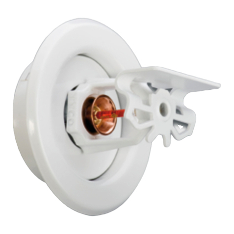
The recessed version of the Series LFII
(TY4334) is intended for use in areas
with finished walls. It employs a two-
piece Style 20 Recessed Escutcheon.
The Recessed Escutcheon provides
1/4 inch (6,4 mm) of recessed adjust-
ment or up to 1/2 inch (12,7 mm) of to-

Page 2 of 6 TFP417
1-3/8" (34,9 mm)
1-1/8" (28,6 mm)
MOUNTING
PLATE
TY4334
MOUNTING
SURFACE
CLOSURE
(73,0 mm)
1/2" (12,7 mm)
(57,2 mm)
2-1/4" DIA.
1/4" (6,4 mm)
1/8"
(3,2 mm)
(11,1±3,2 mm)
SPRINKLER
FITTING
FACE OF
7/16±1/8"
2-7/8" DIA.
BOSS
END-OF-
DEFLECTOR
TOP-OF-
DEFLECTOR
3/8"
(9,5 mm)
Sealing
-
3
5
4
*
6
Compression
of Deflector.
is indicated on top
Temperature rating
Bulb
Deflector
-
-
-
*
1
Components:
2 Button
Frame
-
-
TOP
WRENCH
STYLE 20
RECESSED
ESCUTCHEON
FLATS
2-7/8" DIA.
RECESSED
(73,0 mm)
5
NOMINAL
PLATE SEATING
SURFACE
ESCUTCHEON
1/2" NPT
MAKE-IN
CENTERLINE
OF WATERWAY
7/16" (11,1 mm)
(57,2 mm)
(41,3 mm)
DEFLECTOR
BOSS
(9,5 mm)
3/8"
END-OF-
2-1/4"
1-5/8"
DEFLECTOR
TOP-OF-
FLATS
WRENCH
Ejection Spring7 -
43
7
6
*
1
2
Assembly
Screw
FIGURE 1
SERIES LFII (TY4334) RESIDENTIAL
HORIZONTAL SIDEWALL AND RECESSED HORIZONTAL SIDEWALL SPRINKLERS
WRENCH RECESS
(END "A" USED
FOR TY4334)
RECESS
WRENCH
WITH SPRINKLER
ENGAGEMENT
IN TO ENSURE
WRENCHING AREA
PUSH WRENCH
FIGURE 2
STYLE 20 RECESSED ESCUTCHEON
FOR USE WITH THE SERIES LFII (TY4334)
RESIDENTIAL HORIZONTAL SIDEWALL SPRINKLER
FIGURE 3
W-TYPE 6 SPRINKLER WRENCH
FIGURE 4
W-TYPE 7 RECESSED
SPRINKLER WRENCH

TFP417 Page 3 of 6
Technical
Data
Approvals:
UL and C-UL Listed (Refer to Table A
and the Design Criteria section - Re-
cessed and Non-Recessed).
FM Approved (Refer to Table B
and the Design Criteria section - Re-
cessed and Non-Recessed).
Maximum Working Pressure:
175 psi (12,1 bar)
Discharge Coefficient:
K = 5.8 GPM/psi1/2 (83,5 LPM/bar1/2)
Temperature Rating:
155°F (68°C) or 175°F (79°C)
Finishes:
White Polyester Coated, Chrome
Plated, or Natural Brass
Physical Characteristics:
Frame.................... Brass
Button................... Bronze
Sealing Assembly. . . . . . . . . . . . . . . .
Beryllium Nickel w/Teflon †
Bulb . . . . . . . . . . . . . 3 mm dia. Glass
Compression Screw. . . . . . . . Bronze
Deflector.................. Brass
Ejection Spring. . . . . . Stainless Steel
†Dupont Registered Trademark
Operation
The glass bulb contains a fluid which
expands when exposed to heat. When
the rated temperature is reached, the
fluid expands sufficiently to shatter the
glass bulb, allowing the sprinkler to
activate and water to flow.
Design Criteria
UL AND C-UL LISTING CRITERIA
The Series LFII (TY4334) Residential
Horizontal Sidewall Sprinklers are UL
and C-UL Listed for installation in ac-
cordance with the following criteria.
NOTE
When conditions exist that are outside
the scope of the provided criteria, re-
fer to the Residential Sprinkler Design
Guide TFP490 for the manufacturer’s
recommendations that may be ac-
ceptable to the local Authority Having
Jurisdiction.
System Type. Only wet pipe systems
may be utilized.
Hydraulic Design. The minimum re-
quired sprinkler flow rate for systems
designed to NFPA 13D or NFPA 13R
are given in Table A as a function of
temperature rating and the maximum
allowable coverage areas. The sprin-
kler flow rate is the minimum required
discharge from each of the total num-
ber of “design sprinklers” as specified
in NFPA 13D or NFPA 13R.
For systems designed to NFPA 13, the
number of design sprinklers is to be
the four most hydraulically demanding
sprinklers. The minimum required dis-
charge from each of the four sprinklers
is to be the greater of the following:
• The flow rates given in Table A for
NFPA 13D and 13R as a function of
temperature rating and the maximum
allowable coverage area.
• A minimum discharge of 0.1 gpm/
sq. ft. over the “design area” com-
prised of the four most hydraulically
demanding sprinklers for the actual
coverage areas being protected by
the four sprinklers.
Example No. 1: A corridor being pro-
tected is 8 ft. wide; consequently, an
actual coverage area of 8 ft. x 20 ft.
is being contemplated. Based on us-
ing the LFII (TY4334) Residential Hor-
izontal Sidewall Sprinklers, the flow
rate provided in Table A for a 16 ft x
20 ft. coverage area is 29 GPM. How-
ever based on minimum discharge of
0.1 gpm/sq. ft. the flow rate would be
16 GPM. In this case a minimum flow
rate of 29 GPM for this design sprin-
kler must be utilized.
Example No. 2: The room being pro-
tected is 16 x 16 ft.. Based on using
the LFII (TY4334) Residential Hori-
zontal Sidewall Sprinklers, the flow
rate provided in Table A for a 16 ft. x
16 ft. coverage area is 21 GPM. How-
ever based on minimum discharge of
0.1 gpm/sq. ft. the flow rate would be
26 GPM. In this case a minimum flow
rate of 26 GPM for this design sprin-
kler must be utilized.
Obstruction To Water Distribution.
Locations of sprinklers are to be in ac-
cordance with the obstruction rules of
NFPA 13 for residential sprinklers.
Operational Sensitivity. The sprin-
klers are to be installed with an end-of-
deflector-boss to wall distance of 1-3/8
to 6 inches or in the recessed position
using only the Style 20 Recessed Es-
cutcheon as shown in Figure 2.
In addition the top-of-deflector-to-
ceiling distance is to be within the
range (Ref. Table A) being hydraulically
calculated.
Sprinkler Spacing. The minimum
spacing between sprinklers is 8 feet
(2,4 m). The maximum spacing be-
tween sprinklers can not exceed the
width of the coverage area (Ref. Table
A) being hydraulically calculated (e.g.,
maximum 12 feet for a 12 ft. x 12 ft.
coverage area, or 16 feet for a 16 ft. x
20 ft. coverage area).
FM APPROVAL CRITERIA
The Series LFII (TY4334) Residen-
tial Horizontal Sidewall Sprinklers are
FM Approved for installation in accor-
dance with the applicable Factory Mu-
tual Loss Prevention Data Sheet. Cri-
teria provided by FM may differ for UL
and/or NFPA, therefore the designer
should review and become familiar
with Factory Mutual requirements be-
fore proceeding with design
NOTE
When conditions exist that are outside
the scope of the provided criteria, re-
fer to the Residential Sprinkler Design
Guide TFP490 for the manufacturer’s
recommendations that may be ac-
ceptable to the local Authority Having
Jurisdiction.
The following information pertaining to
System Type, Hydraulic Design, and
Sprinkler spacing are provided for ref-
erence and are not intended to provide
complete installation criteria as pro-
vided in the applicable Factory Mutual
Loss Prevention Data Sheet.
System Type. Only wet pipe systems
may be utilized.
Hydraulic Design. The number of de-
sign sprinklers is to be the four most
hydraulically demanding sprinklers.
The minimum required discharge from
each of the four sprinklers is to be
greater than the following:
• The flow rates given in Table B as a
function of the maximum allowable
coverage area.
• A minimum discharge of 0.1 gpm/
sq. ft. over the “design area” com-
prised of the four most hydraulically
demanding sprinklers for the actual
coverage areas being protected by
the four sprinklers.
Example No. 1: A corridor being pro-
tected is 8 ft. wide; consequently, an
actual coverage area of 8 ft. x 20 ft.
is being contemplated. Based on us-
ing the LFII (TY4334) Residential Hor-
izontal Sidewall Sprinklers, the flow
rate provided in Table B for a 16 ft x
20 ft. coverage area is 32 GPM. How-
ever based on minimum discharge of
0.1 gpm/sq. ft. the flow rate would be
16 GPM. In this case a minimum flow
rate of 32 GPM for this design sprin-
kler must be utilized.
Example No. 2: The room being pro-
tected is 16 x 16 ft.. Based on using
the LFII (TY4334) Residential Hori-
zontal Sidewall Sprinklers, the flow
rate provided in Table B for a 16 ft x
16 ft. coverage area is 24 GPM. How-
ever based on minimum discharge of
0.1 gpm/sq. ft. the flow rate would be
26 GPM. In this case a minimum flow
rate of 26 GPM for this design sprin-
kler must be utilized.
(Continued on Page 5)
Page 4 of 6 TFP417
Maximum
Coverage Area(a)
Width x Length(b)
Ft. x Ft. (m x m)
Maximum
Spacing
Ft. (m)
Minimum Flow(c) and Residual Pressure
Top- Of- Deflector- To- Ceiling:
4 to 6 Inches (102 to 152 mm)
Top- Of- Deflector- To- Ceiling:
6 to 12 Inches (152 to 305 mm)
155° F/68° C 175° F/79° C 155° F/68° C 175° F/79° C
Recessed or Non-Recessed
12 x 12
(3,7 x 3,7)
12
(3,7)
19 GPM (71,9 LPM)
10.7 psi (0,74 bar)
19 GPM (71,9 LPM)
10.7 psi (0,74 bar)
19 GPM (71,9 LPM)
10.7 psi (0,74 bar)
19 GPM (71,9 LPM)
10.7 psi (0,74 bar)
14 x 14
(4,3 x 4,3)
14
(4,3)
21 GPM (79,5 LPM)
13.1 psi (0,90 bar)
21 GPM (79,5 LPM)
13.1 psi (0,90 bar)
23 GPM (87,1 LPM)
15.7 psi (1,08 bar)
23 GPM (87,1 LPM)
15.7 psi (1,08 bar)
16 x 14
(4,9 x 4,3)
16
(4,9)
21 GPM (79,5 LPM)
13.1 psi (0,90 bar)
21 GPM (79,5 LPM)
13.1 psi (0,90 bar)
23 GPM (87,1 LPM)
15.7 psi (1,08 bar)
23 GPM (87,1 LPM)
15.7 psi (1,08 bar)
16 x 16
(4,9 x 4,9)
16
(4,9)
21 GPM (79,5 LPM)
13.1 psi (0,90 bar)
21 GPM (79,5 LPM)
13.1 psi (0,90 bar)
23 GPM (87,1 LPM)
15.7 psi (1,08 bar)
23 GPM (87,1 LPM)
15.7 psi (1,08 bar)
16 x 18
(4,9 x 5,5)
16
(4,9)
23 GPM (87,1 LPM)
15.7 psi (1,08 bar)
23 GPM (87,1 LPM)
15.7 psi (1,08 bar)
24 GPM (90,8 LPM)
17.1 psi (1,18 bar)
24 GPM (90,8 LPM)
17.1 psi (1,18 bar)
16 x 20
(4,9 x 6,1)
16
(4,9)
29 GPM (109,8 LPM)
25.0 psi (1,72 bar)
29 GPM (109,8 LPM)
25.0 psi (1,72 bar)
30 GPM (113,6 LPM)
26.8 psi (1,85 bar)
30 GPM (113,6 LPM)
26.8 psi (1,85 bar)
18 x 18
(5,5 x 5,5)
18
(5,5)
29 GPM (109,8 LPM)
25.0 psi (1,72 bar)
29 GPM (109,8 LPM)
25.0 psi (1,72 bar)
30 GPM (113,6 LPM)
26.8 psi (1,85 bar)
30 GPM (113,6 LPM)
26.8 psi (1,85 bar)
Non-Recessed
16 x 22
(4,9 x 6,7)
16
(4,9)
38 GPM (143,8 LPM)
42.9 psi (2,96 bar)
38 GPM (143,8 LPM)
42.9 psi (2,96 bar)
40 GPM (151,4 LPM)
47.6 psi (2,96 bar)
40 GPM (151,4 LPM)
47.6 psi (2,96 bar)
(a) For coverage area dimensions less than or between those indicated, it is necessary to use the minimum required flow for the
next highest coverage area for which hydraulic design criteria are stated.
(b) Width (backwall where sprinkler is located) x Length (horizontal throw of sprinkler).
(c) Requirement is based on minimum flow in GPM (LPM) from each sprinkler. The associated residual pressures are calculated
using the nominal K-factor. Refer to Hydraulic Design Criteria Section for details.
(d) Sidewall sprinklers, where installed under a ceiling with a slope greater than 0 inch rise for a 12 inch run to a slope up to
2 inch rise for 12 inch run, must be located per one of the following:
• Locate the sprinklers at the high point of the slope and positioned to discharge down the slope.
• Locate the sprinklers along the slope and positioned to discharge across the slope.
TABLE A
UL AND C-UL LISTED
NFPA 13D AND NFPA 13R HYDRAULIC DESIGN CRITERIA
FOR THE SERIES LFII (TY4334) RESIDENTIAL
HORIZONTAL SIDEWALL AND RECESSED HORIZONTAL SIDEWALL SPRINKLERS
FOR HORIZONTAL CEILING (MAXIMUM 2 INCH RISE FOR 12 INCH RUN (d))

TFP417 Page 5 of 6
Maximum
Coverage Area(a)
Width x Length(b)
Ft. x Ft. (m x m)
Maximum
Spacing
Ft. (m)
Minimum Flow(c)
and Residual Pressure
Top- Of- Deflector- To- Ceiling:
4 to 12 Inches (102 to 305 mm)
175° F/79° C
Recessed or Non-Recessed
12 x 12
(3,7 x 3,7)
12
(3,7)
22 GPM (83,3 LPM)
14.4 psi (0,99 bar)
14 x 14
(4,3 x 4,3)
14
(4,3)
22 GPM (83,3 LPM)
14.4 psi (0,99 bar)
16 x 16
(4,9 x 4,9)
16
(4,9)
24 GPM (90,8 LPM)
17.1 psi (1,18 bar)
16 x 18
(4,9 x 5,5)
16
(4,9)
28 GPM (106,0 LPM)
23.3 psi (1,61 bar)
16 x 20
(4,9 x 6,1)
16
(4,9)
32 GPM (121,0 LPM)
30.4 psi (2,10 bar)
18 x 18
(5,5 x 5,5)
18
(5,5)
33 GPM (125,0 LPM)
32.4 psi (2,23 bar)
(a) For coverage area dimensions less than or between those indicated,
it is necessary to use the minimum required flow for the next highest
coverage area for which hydraulic design criteria are stated.
(b) Width (backwall where sprinkler is located) x Length (horizontal throw
of sprinkler).
(c) Requirement is based on minimum flow in GPM (LPM) from each
sprinkler. The associated residual pressures are calculated using the
nominal K-factor. Refer to Hydraulic Design Criteria Section for details.
(d) Sidewall sprinklers, where installed under a ceiling with a slope greater
than 0 inch rise for a 12 inch run to a slope up to
2 inch rise for 12 inch run, must be located per one of the following:
• Locate the sprinklers at the high point of the slope and positioned to
discharge down the slope.
• Locate the sprinklers along the slope and positioned to discharge
across the slope.
TABLE B
FM APPROVED
HYDRAULIC DESIGN CRITERIA
FOR THE SERIES LFII (TY4334) RESIDENTIAL
HORZ. SIDEWALL AND REC. HORZ. SIDEWALL SPRINKLERS
FOR HORZ. CEILING
(MAXIMUM 2 INCH RISE FOR 12 INCH RUN (d))
Sprinkler Spacing. The minimum
spacing between sprinklers is 8 feet
(2,4 m). The maximum spacing be-
tween sprinklers can not exceed the
width of the coverage area (Ref. Table
B) being hydraulically calculated (e.g.,
maximum 12 feet for a 12 ft. x 12 ft.
coverage area, or 16 feet for a 16 ft. x
20 ft. coverage area).
Installation
The Series LFII (TY4334) must be in-
stalled in accordance with the follow-
ing instructions:
NOTES
Do not install any bulb type sprinkler
if the bulb is cracked or there is a loss
of liquid from the bulb. With the sprin-
kler held horizontally, a small air bub-
ble should be present. The diameter
of the air bubble is approximately 1/16
inch (1,6 mm).
A 1/2 inch NPT sprinkler joint should
be obtained with a minimum to maxi-
mum torque of 7 to 14 ft. lbs. (9,5 to
19,0 Nm). Higher levels of torque may
distort the sprinkler inlet with conse-
quent leakage or impairment of the
sprinkler.
Do not attempt to compensate for in-
sufficient adjustment in an Escutcheon
Plate by under- or over-tightening the
Sprinkler. Readjust the position of the
sprinkler fitting to suit.
The Series LFII Horizontal Sidewall
Sprinklers must be installed in accor-
dance with the following instructions.
Step 1. Horizontal sidewall sprinklers
are to be installed in the horizontal po-
sition with their centerline of waterway
perpendicular to the back wall and
parallel to the ceiling. The word “TOP”
on the Deflector is to face towards the
ceiling with the front edge of the De-
flector parallel to the ceiling.
Step 2. With pipe thread sealant ap-
plied to the pipe threads, hand tighten
the sprinkler into the sprinkler fitting.
Step 3. Tighten the sprinkler into the
sprinkler fitting using only the W-Type
6 Sprinkler Wrench (Ref. Figure 3).
With reference to Figure 1, the W-Type
6 Sprinkler Wrench is to be applied to
the wrench flats.
The Series LFII Recessed Horizontal
Sidewall Sprinklers must be installed
in accordance with the following
instructions.
Step A. Recessed horizontal sidewall
sprinklers are to be installed in the hor-
izontal position with their centerline of
waterway perpendicular to the back
wall and parallel to the ceiling. The
word “TOP” on the Deflector is to face
towards the ceiling.
Step B. After installing the Style 20
Mounting Plate over the sprinkler
threads and with pipe thread seal-
ant applied to the pipe threads, hand
tighten the sprinkler into the sprinkler
fitting.
Step C. Tighten the sprinkler into the
sprinkler fitting using only the W-Type 7
Recessed Sprinkler Wrench (Ref. Fig-
ure 4). With reference to Figure 1, the
W-Type 7 Recessed Sprinkler Wrench
is to be applied to the sprinkler wrench
flats.
Step D. After the wall has been in-
stalled or the finish coat has been ap-
plied, slide on the Style 20 Closure
over the Series LFII Sprinkler and push
the Closure over the Mounting Plate
until its flange comes in contact with
the wall.

Page 6 of 6 TFP417
©2008 TYCO FIRE & BUILDING PRODUCTS
, 451 North Cannon Avenue, Lansdale Pennsylvania 19446
Care and
Maintenance
The Tyco®Rapid Response™ Series
LFII (TY4334) must be maintained and
serviced in accordance with the fol-
lowing instructions:
NOTES
Absence of an Escutcheon Plate may
delay the sprinkler operation in a fire
situation.
Before closing a fire protection system
main control valve for maintenance
work on the fire protection system
which it controls, permission to shut
down the affected fire protection sys-
tem must be obtained from the prop-
er authorities and all personnel who
may be affected by this action must be
notified.
Sprinklers which are found to be leak-
ing or exhibiting visible signs of corro-
sion must be replaced.
Automatic sprinklers must never be
painted, plated, coated, or otherwise
altered after leaving the factory. Mod-
ified sprinklers must be replaced to
corrosive products of combustion, but
have not operated, should be replaced
if they can not be completely cleaned
by wiping the sprinkler with a cloth or
by brushing it with a soft bristle brush.
Care must be exercised to avoid dam-
age to the sprinklers- before, during,
and after installation. Sprinklers dam-
aged by dropping, striking, wrench
twist/slippage, or the like, must be re-
placed. Also, replace any sprinkler that
has a cracked bulb or that has lost
liquid from its bulb. (Ref. Installation
Section).
The owner is responsible for the in-
spection, testing, and maintenance of
their fire protection system and devic-
es in compliance with this document,
as well as with the applicable stan-
dards of the National Fire Protection
Association (e.g., NFPA 25), in addition
to the standards of any other authori-
ties having jurisdiction. The installing
contractor or sprinkler manufacturer
should be contacted relative to any
questions.
NOTE
The owner must assure that the sprin-
klers are not used for hanging of any
objects and that the sprinklers are only
cleaned by means of gently dusting
with a feather duster; otherwise, non-
operation in the event of a fire or inad-
vertent operation may result.
Automatic sprinkler systems should be
inspected, tested, and maintained by a
qualified Inspection Service in accor-
dance with local requirements and/or
national code.
Limited
Warranty
Products manufactured by Tyco Fire
& Building Products (TFBP) are war-
ranted solely to the original Buyer for
ten (10) years against defects in mate-
rial and workmanship when paid for
and properly installed and maintained
under normal use and service. This
warranty will expire ten (10) years from
date of shipment by TFBP. No warran-
ty is given for products or components
manufactured by companies not af-
filiated by ownership with TFBP or for
products and components which have
been subject to misuse, improper in-
stallation, corrosion, or which have not
been installed, maintained, modified or
repaired in accordance with applicable
Standards of the National Fire Protec-
tion Association, and/or the standards
of any other Authorities Having Juris-
diction. Materials found by TFBP to be
defective shall be either repaired or re-
placed, at TFBP’s sole option. TFBP
neither assumes, nor authorizes any
person to assume for it, any other ob-
ligation in connection with the sale of
products or parts of products. TFBP
shall not be responsible for sprinkler
system design errors or inaccurate or
incomplete information supplied by
Buyer or Buyer’s representatives.
In no event shall TFBP be liable, in
contract, tort, strict liability or under
any other legal theory, for incidental,
indirect, special or consequential dam-
ages, including but not limited to labor
charges, regardless of whether TFBP
was informed about the possibility of
such damages, and in no event shall
TFBP’s liability exceed an amount
equal to the sales price.
The foregoing warranty is made in lieu
of any and all other warranties, ex-
press or implied, including warranties
of merchantability and fitness for a
particular purpose.
This limited warranty sets forth the ex-
clusive remedy for claims based on
failure of or defect in products, materi-
als or components, whether the claim
is made in contract, tort, strict liability
or any other legal theory.
This warranty will apply to the full ex-
tent permitted by law. The invalidity,
in whole or part, of any portion of this
warranty will not affect the remainder.
Ordering
Procedure
When placing an order, indicate the full
product name. Contact your local dis-
tributor for availability.
Sprinkler Assembly:
Series LFII (TY4334), K=5.8, Resi-
dential Horizontal Sidewall Sprinkler
with (specify) temperature rating and
(specify) finish, P/N (specify).
155°F/68° C
Chrome Plated . . . . . . . . . . . . P/N 51-534-9-155
White Coated . . . . . . . . . . . . . P/N 51-534-4-155
Natural Brass . . . . . . . . . . . . . P/N 51-534-1-155
175° F/79° C
Chrome Plated . . . . . . . . . . . . P/N 51-534-9-175
White Coated . . . . . . . . . . . . . P/N 51-534-4-175
Natural Brass . . . . . . . . . . . . . P/N 51-534-1-175
Recessed Escutcheon:
Specify: Style 20 Recessed Escutcheon
with (specify*) finish, P/N (specify*).
* Refer to Technical Data Sheet TFP770.
Sprinkler Wrench:
Specify: W-Type 6 Sprinkler Wrench,
P/N 56-000-6-387.
Specify: W-Type 7 Sprinkler Wrench,
P/N 56-850-4-001.
Table of contents
Other Tyco Irrigation System manuals

Tyco
Tyco RFII Series User manual

Tyco
Tyco TY-FRB Series User manual

Tyco
Tyco LFII Series User manual

Tyco
Tyco LFII Series Instruction Manual

Tyco
Tyco ESFR-1 User manual

Tyco
Tyco Mulsifyre F822 User manual

Tyco
Tyco DS-2 Series User manual

Tyco
Tyco DS-1 TY3255 Operating and maintenance instructions

Tyco
Tyco TFP PH5 Owner's manual

Tyco
Tyco ESFR-17 User manual

Tyco
Tyco TFP PH2 Instruction Manual

Tyco
Tyco ESFR-17 User manual

Tyco
Tyco RAPID RESPONSE Series User manual

Tyco
Tyco ESFR-1 User manual

Tyco
Tyco ESFR-25 User manual

Tyco
Tyco AM11 User manual

Tyco
Tyco Central ESFR-25/WilFlow User manual

Tyco
Tyco BB User manual

Tyco
Tyco Rapidresponse LFII Series User manual

Tyco
Tyco TY-FRB Series Instruction Manual