Tyco DS-1 Series User manual

Series DS-1 – 5.6 K-factor, Dry-Type Sprinklers,
Pendent, Standard Response, Standard Coverage
VdS Approved Criteria
Page 1 of 6 JUNE 2019 TFP501
IMPORTANT
Refer to Technical Data Sheet
TFP2300 for warnings pertaining to
regulatory and health information.
Always refer to Technical Data
Sheet TFP700 for the “INSTALLER
WARNING” that provides cautions
with respect to handling and instal-
lation of sprinkler systems and com-
ponents. Improper handling and
installation can permanently damage
a sprinkler system or its compo-
nents and cause the sprinkler to fail
to operate in a fire situation or cause
it to operate prematurely.
Worldwide
Contacts
www.tyco-fire.com
General
Description
TYCO Series DS-1 5.6K Pendent, Stan-
dard Response (5 mm bulb), Standard
Coverage Dry-Type Sprinklers are dec-
orative glass bulb automatic sprinklers
typically used where:
• pendent sprinklers are required on
dry pipe systems that are exposed
to freezing temperatures (e.g., sprin-
kler drops from unheated portions of
buildings)
• sprinklers and/or a portion of the
connecting piping may be exposed
to freezing temperatures (e.g., sprin-
kler drops from wet systems into
freezers, sprinkler sprigs from wet
systems into unheated attics, to
protect unheated areas of a building
such as loading docks, overhangs,
and building exteriors)
• sprinklers are used on systems that
are seasonably drained to avoid
freezing (e.g., vacation resort areas)
NOTICE
Series DS-1 Dry-Type Sprinklers
described herein must be installed
and maintained in compliance with this
document, as well as with the appli-
cable standards of the VdS CEA 4001
“Sprinkler System: Planning and Instal-
lation” or EN12845 “Fixed Firefight-
ing Systems - Design, Installation and
Maintenance”, in addition to the stan-
dards of any other authorities having
jurisdiction. Failure to do so may impair
the performance of these devices.
The owner is responsible for main-
taining their fire protection system
and devices in proper operating con-
dition. Contact the installing contrac-
tor or product manufacturer with any
questions.
Series DS-1 Dry-Type Sprinklers must
only be installed in fittings that meet
the requirements of the Design Crite-
ria section.
Sprinkler
Identification
Numbers (SINs)
TY3255 – Pendent
Technical
Data
Approvals
VdS Approved
Maximum Working Pressure
175 psi (12,1 bar)
Inlet Thread Connections
ISO 7-R 1
Discharge Coefficient
K=5.6 gpm/psi½(80,6 lpm/bar½)
Temperature Ratings
135°F (57°C)
155°F (68°C)
175°F (79°C)
200°F (93°C)
286°F (141°C)
360°F (182°C)
Finishes
Sprinkler: Natural Brass, Chrome Plated,
Signal White (RAL9003) Polyester
Escutcheon: Brass Plated, Chrome
Plated, Signal White (RAL9003) Polyester,
Stainless Steel
Baffle Plate: Chrome Plated
Physical Characteristics
Inlet . . . . . . . . . . . . . . . . . . . . . . . . . . . . . Copper
Plug . . . . . . . . . . . . . . . . . . . . . . . . . . . . . Copper
Yoke....................... Stainless Steel
Casing .............Galvanized Carbon Steel
Insert . . . . . . . . . . . . . . . . . . . . . . . . . . . . .Bronze
Bulb Seat. . . . . . . . . . . . . . . . . . . Stainless Steel
Bulb (5 mm dia.) . . . . . . . . . . . . . . . . . . . . . Glass
Compression Screw . . . . . . . . . . . . . . . . .Bronze
Deflector . . . . . . . . . . . . . . . . . . . . . . . . . .Bronze
Frame . . . . . . . . . . . . . . . . . . . . . . . . . . . .Bronze
Guide Tube . . . . . . . . . . . . . . . . . Stainless Steel
Water Tube . . . . . . . . . . . . . . . . . Stainless Steel
Spring ..................... Stainless Steel
Sealing Assembly ..Beryllium Nickel w/TEFLON
Escutcheon . . . . . . . . . . . . . . . . . . .Carbon Steel
Operation
When TYCO Series DS-1 5.6K Pendent,
Standard Response, Standard Cover-
age Dry-Type Sprinklers are in service,
water is prevented from entering the
assembly by the Plug with Sealing
Assembly (See Figure 1) in the Inlet of
the sprinkler.
The glass bulb contains a fluid that
expands when exposed to heat. When
the rated temperature is reached, the
fluid expands sufficiently to shatter
the glass bulb, and the Bulb Seat is
released.
The compressed Spring is then able
to expand and push the Water Tube as
well as the Guide Tube outward. This
action simultaneously pulls inward on
the Yoke, withdrawing the Plug with
Sealing Assembly from the Inlet, allow-
ing the sprinkler to activate and flow
water.

TFP501
Page 2 of 6
Design
Criteria
TYCO Series DS-1 5.6K Pendent, Stan-
dard Response, Standard Coverage
Dry-Type Sprinklers are intended for
use in fire sprinkler systems designed in
accordance with the standard installa-
tion rules. For more information contact
Johnson Controls Technical Services.
The unused outlet of the threaded tee is
plugged as shown in Figure 6.
Series DS-1 Dry-Type Sprinkler may
also be installed in the outlet of a
GRINNELL G-FIRE Figure 522 Sprinkler
Outlet Fittings with ISO 7-R1 threads;
however, the use of the Figure 522 for
this arrangement is limited to wet pipe
systems.
The configuration shown in Figure 7 is
only applicable for wet pipe systems
where the sprinkler fitting and water-
filled pipe above the sprinkler fitting are
not subject to freezing and where the
length of the dry-type sprinkler has the
minimum exposure length depicted in
Figure 5. Refer to the Exposure Length
section.
NOTICE
Do not install Series DS-1 Dry-Type
Sprinklers into any other type fitting
without first consulting the Johnson
Controls Technical Services. Failure to
use the appropriate fitting may result in
one of the following:
•
failure of the sprinkler to operate
properly due to formation of ice
over the Inlet Plug or binding of the
Inlet Plug
•
insufficient engagement of the
Inlet pipe-threads with consequent
leakage
Drainage
Follow installation instructions accord-
ing to VdS CEA 4001 to set pitch for
proper drainage.
Exposure Length
When using Dry Sprinklers in wet pipe
sprinkler systems to protect areas
Sprinkler Fittings
Install ISO 7-R1 DS-1 Dry-Type Sprin-
klers in the ISO 7-R1 outlet or run of the
ductile iron threaded tees fittings that
meet the dimensional requirements of
EN10242.
Do not install Series DS-1 Dry-Type
Sprinklers into elbow fittings. The Inlet
of the sprinkler can contact the interior
of the elbow.
ORDER LENGTHS:
(69,9 to 1219,2 mm)
2-3/4" to 48"
IN 1/4" (6,4 mm)
INCREMENTS
FITTING
FACE OF
SPRINKLER
(76,2 mm)
3" DIA.
1-3/4" DIA.
(44,5 mm)
(55,6 ± 3,2 mm)
2-3/16" ± 1/8"
CEILING
FACE OF
SPRINKLER FITTING
(REFER TO DESIGN
CRITERIA SECTION)
BULB
WATER
TUBE
VENT HOLE
GUIDE
TUBE
INSERT
YOKE
INLETPLUG WITH
SEALING
ASSEMBLY
CASING
DEFLECTOR
BULB
SEAT
SPRING
COMPRESSION
SCREW
FRAME
INLET
BAND
MOUNTING
CUP
RECESS
WRENCH
FLAT
WRENCH
WITH SPRINKLER
ENGAGEMENT
IN TO ENSURE
WRENCHING AREA
PUSH WRENCH
ORDER LENGTHS:
5" to 48"
(127,0 to 1219,2 mm)
IN 1/4" (6,4 mm)
INCREMENTS
FACE OF
SPRINKLER
FITTING
4-1/8" DIA.
(105 mm)
SPRINKLER FITTING
(REFER TO DESIGN
CRITERIA SECTION)
FIGURE 1
SERIES DS-1 DRY-TYPE SPRINKLER, 5.6K, STANDARD RESPONSE
ASSEMBLY
FIGURE 2
W-T YPE 7
WRENCH
FIGURE 3
SERIES DS-1 DRY-TYPE
PENDENT SPRINKLER (TY3255)
WITH STANDARD ESCUTCHEON
FIGURE 4
SERIES DS-1 DRY-TYPE
PENDENT SPRINKLER (TY3255)
WITH BAFFLE

TFP501
Page 3 of 6
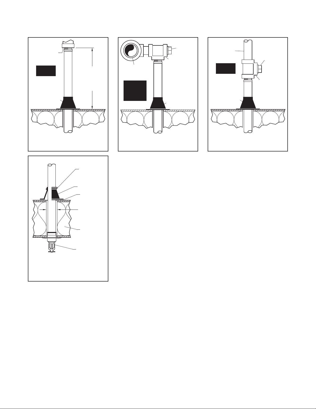
subject to freezing temperatures, use
Table A to determine a sprinkler’s
appropriate exposed barrel length to
prevent water from freezing in the con-
necting pipes due to conduction. The
exposed barrel length measurement
must be taken from the face of the
sprinkler fitting to the surface of the
structure or insulation that is exposed
to the heated area. Refer to Figure 5 for
an example.
For protected area temperatures
between those given above, the
minimum recommended length from
the face of the fitting to the outside of
the protected area may be determined
by interpolating between the indicated
values.
Clearance Space
In accordance with VdS CEA 4001,
when connecting an area subject to
freezing and an area containing a
wet pipe sprinkler system, the clear-
ance space around the sprinkler
barrel of dry-type sprinklers must be
sealed. Due to temperature differences
between two areas, the potential for
the formation of condensation in the
sprinkler and subsequent ice build-up
is increased. If this condensation is not
controlled, ice build-up can occur that
might damage the dry-type sprinkler
and/or prevent proper operation in a
re situation.
Use of the Model DSB-2 Dry Sprinkler
Boot, described in technical data sheet
TFP591 and shown in Figures 8, can
provide the recommended seal.
Installation
TYCO Series DS-1 5.6K Pendent, Stan-
dard Response, Standard Coverage
Dry-Type Sprinklers must be installed
in accordance with this section.
General Instructions
Series DS-1 Dry-Type Sprinklers must
only be installed in fittings that meet
the requirements of the Design Crite-
ria section. Refer to the Design Criteria
section for other important require-
ments regarding piping design and
sealing of the clearance space around
the Sprinkler Casing.
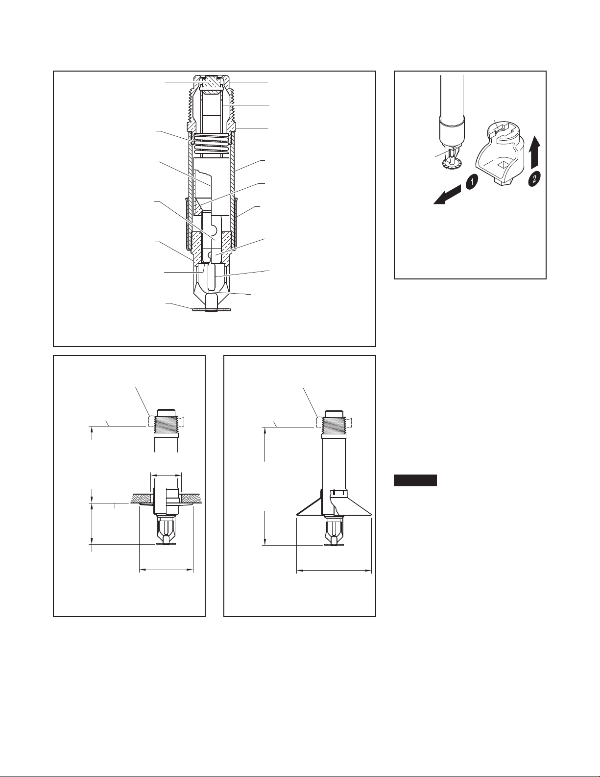
Do not install any bulb-type sprinkler
if the bulb is cracked or there is a loss
of liquid from the bulb. With the sprin-
kler held horizontally, a small air bubble
should be present. The diameter of the
air bubble is approximately 1/16 in.
(1,6 mm) for the 135°F (57°C) rating to
1/8 in. (3,2 mm) for the 360°F (182°C)
rating.
Obtain a leak-tight ISO 7-R1 sprinkler
joint by applying a minimum-to-maxi-
mum torque of 20 to 30 lb-ft (26,8 to
40,2 N·m). Higher levels of torque may
distort the sprinkler Inlet with conse-
quent leakage or impairment of the
sprinkler.
Do not attempt to compensate for
insufficient adjustment in an Escutch-
eon Plate by under or over-tightening
the Sprinkler. Re-adjust the position of
the sprinkler fitting to suit.
Note: Install pendent sprinklers only in
the pendent position. The deflector of
a pendent sprinkler is to be parallel to
the ceiling.
Step 1. With a non-hardening pipe-
thread sealant such as TEFLON applied
to the inlet threads, hand-tighten the
sprinkler into the sprinkler fitting.
Step 2. Wrench-tighten the sprinkler
using either:
• a pipe wrench on the Inlet Band or
the Casing (See Figure 1)
• the W-Type 7 Sprinkler Wrench on
the Wrench Flat (See Figure 2)
Apply the wrench recess of the W-Type
7 Sprinkler Wrench to the wrench flat.
Note: If sprinkler removal becomes
necessary, remove the sprinkler using
the same wrenching method noted
above. Sprinkler removal is easier when
a non-hardening sealant was used
and torque guidelines were followed.
After removal, inspect the sprinkler for
damage.
Step 3. After installing the ceiling and
applying a ceiling finish, slide on the
outer piece of the escutcheon until
it comes in contact with the ceiling.
Do not lift the ceiling panel out of its
normal position.
To install the baffle plate properly, push
on until the top edge reaches the flared
edge of the escutcheon.
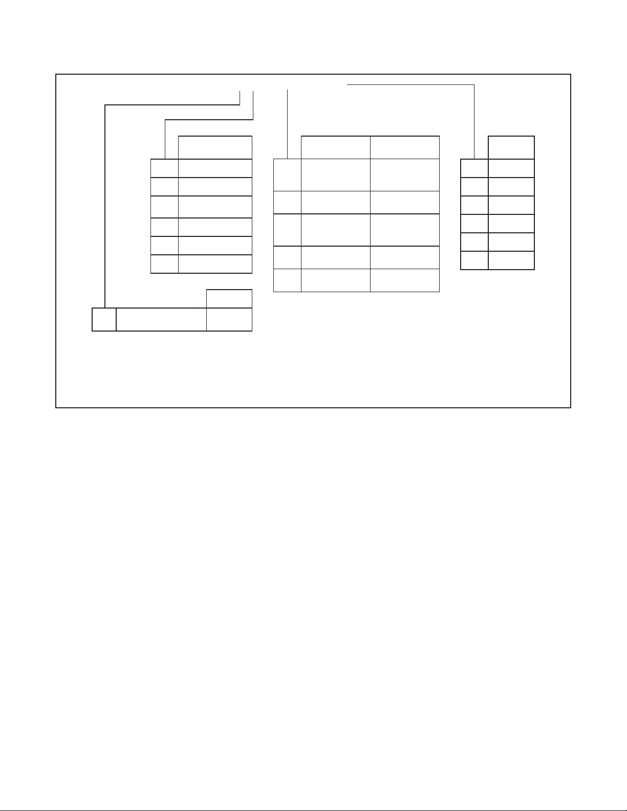
Ambient Temperature
Exposed to
Discharge End of Sprinkler
Temperatures for Heated Area(1)
40°F
(4°C) 50°F
(10°C) 60°F
(16°C)
Minimum Exposed Barrel Length(2),
Inches
(mm)
40°F
(4°C) 000
30°F
(-1°C) 000
20°F
(-7°C)
4
(100) 0 0
10°F
(-12°C)
8
(200)
1
(25) 0
0°F
(-18°C)
12
(305)
3
(75) 0
-10°F
(-23°C)
14
(355)
4
(100)
1
(25)
-20°F
(-29°C)
14
(355)
6
(150)
3
(75)
-30°F
(-34°C)
16
(405)
8
(200)
4
(100)
-40°F
(-40°C)
18
(455)
8
(200)
4
(100)
-50°F
(-46°C)
20
(510)
10
(255)
6
(150)
-60°F
(-51°C)
20
(510)
10
(255)
6
(150)
Notes:
1. For protected area temperatures that occur between values listed above, use the next cooler temperature.
2. These lengths are inclusive of wind velocities up to 30 mph (18,6 kph).
TABLE A
EXPOSED SPRINKLER BARRELS IN WET PIPE SYSTEMS
MINIMUM RECOMMENDED LENGTHS

TFP501
Page 4 of 6
Automatic sprinklers must never be
painted, plated, coated, or other-
wise altered after leaving the factory.
Modified sprinklers must be replaced.
Sprinklers that have been exposed to
corrosive products of combustion, but
have not operated, should be replaced
if they cannot be completely cleaned
by wiping the sprinkler with a cloth or
by brushing it with a soft bristle brush.
Care must be exercised to avoid
damage to the sprinklers before,
during, and after installation. Sprin-
klers damaged by dropping, striking,
wrench twist/slippage, or the like, must
be replaced. Also, replace any sprin-
kler that has a cracked bulb or that has
lost liquid from its bulb (See Installa-
tion section).
The owner is responsible for the
inspection, testing, and maintenance of
their fire protection system and devices
in compliance with this document, as
well as with the applicable standards
of the VdS CEA 4001, in addition to
the standards of any other authorities
having jurisdiction. Contact the install-
ing contractor or product manufacturer
with any questions.
Automatic sprinkler systems are rec-
ommended to be inspected, tested,
and maintained by a qualified Inspec-
tion Service in accordance with local
requirements and/or national codes.
Care and
Maintenance
TYCO Series DS-1 5.6K Pendent, Stan-
dard Response, Standard Coverage
Dry-Type Sprinklers must be main-
tained and serviced in accordance with
this section.
Before closing a fire protection system
main control valve for maintenance
work on the fire protection system
that it controls, obtain permission to
shut down the affected fire protection
systems from the proper authorities
and notify all personnel who may be
affected by this action.
Absence of the outer piece of an
escutcheon, which is used to cover a
clearance hole, may delay the time to
sprinkler operation in a fire situation.
A Vent Hole is provided in the Bulb
Seat (See Figure 1) to indicate if the Dry
Sprinkler is remaining dry. Evidence of
leakage from the Vent Hole indicates
potential leakage past the Inlet seal
and the need to remove the sprinkler
to determine the cause of leakage;
for example, an improper installation
or an ice plug. Close the fire protec-
tion system control valve and drain the
system before removing the sprinkler.
Sprinklers which are found to be
leaking or exhibiting visible signs of
corrosion must be replaced.
INSULATED
FREEZER
STRUCTURE
STRAP TIES
(ENDS ON
OPPOSING
SIDES OF
BOOT)
ADHESIVE
DS-1
SHOWN WITH
STANDARD
ESCUTCHEON
1-3/4" DIA.
(44,5 mm)
CLEARANCE
HOLE
DSB-2 BOOT
SIDE
OUTLET
PLUGGED
TO WET
SYSTEM
FITTING
(SEE DESIGN
CRITERIA
SECTION)
SPRINKLER
DSB-2
INTENDED
FOR FREEZER
STRUCTURES
HEATED
AREA
RUN
OUTLET
PLUGGED
TO DRY
SYSTEM
DSB-2
INTENDED
FOR FREEZER
STRUCTURES
FITTING
(SEE DESIGN
CRITERIA
SECTION)
SPRINKLER
AREA
SUBJECT
TO
FREEZING
(SEE DESIGN
CRITERIA
SECTION)
FACE OF
SPRINKLER
FITTING
LENGTH
EXPOSURE
DSB-2
INTENDED
FOR FREEZER
STRUCTURES
HEATED
AREA
FIGURE 5
EXPOSURE LENGTH
FIGURE 6
SPRINKLER FITTING
UNHEATED AREA
FIGURE 7
SPRINKLER FITTING
HEATED AREA
FIGURE 8
MODEL DSB-2 DRY SPRINKLER
BOOT WITH PENDENT SERIES
DS-1 DRY-TYPE SPRINKLER

TFP501
Page 5 of 6
Limited
Warranty
For warranty terms and conditions, visit
www.tyco-fire.com.
Ordering
Procedure
Contact your local distributor for avail-
ability. When placing an order, indi-
cate the full product name, including
description and part number (P/N).
Dry-type Sprinklers
When ordering Series DS-1 5.6K
Pendent, Standard Response, Stan-
dard Coverage Dry-Type Sprinklers,
specify the following information:
• SIN:
TY3255 - Pendent
• Order Length:
Dry-Type Sprinklers are furnished
based upon Order Length as mea-
sured per Figures 3 and 4, as appli-
cable. After the measurement is
taken, round it to the nearest 1/4 in.
increment.
• Inlet Connections:
ISO 7-R 1
(For information on ISO Inlet Thread
Connections, contact your Johnson
Controls Sales Representative.)
• Temperature Rating
• Sprinkler Finish
• Escutcheon Type and Finish, as
applicable
• P/N from Table B
Part numbers are for standard order
sprinklers. Orders for all other sprin-
kler assemblies must be accompa-
nied by a complete description.
Sprinkler Wrench
Specify: W-Type 7 Sprinkler Wrench,
P/N 56-850-4-001
Sprinkler Boot
Specify: Model DSB-2 Dry Sprinkler
Boot, P/N 63-000-0-002
NOTE: This part number includes one
(1) Boot, two (2) Strap Ties, and 1/3 oz.
of Adhesive (a sufficient quantity for
installing one boot).
Baffle Plate
Specify: Baffle Plate, P/N 91-070-9-444
P/ N*I - 60 – XXX – X – XXX
ORDER
LENGTH(3)
055 5.50 in.
082 8.25 in.
180 18.00 in.
187 18.75 in.
372 37. 25 i n .
480 48.00 in.
SIN
96 Pendent with
Standard Escutcheon
TY3255
(Figure 3)
SPRINKLER
FINISH ESCUTCHEON
FINISH(1)
0CHROME
PL ATED
SIGNAL WHITE
(RAL9003)
POLYESTER
2NATURAL
BRASS
BRASS
PL ATED
4
SIGNAL WHITE
(RAL9003)
POLYESTER
SIGNAL WHITE
(RAL9003)
POLYESTER
8CHROME
PL ATED
STAINLESS
STEEL
9CHROME
PL ATED
CHROME
PL ATED
TEMPERATURE
RATING(2)
0135°F (57°C)
1155°F (68°C)
2175°F (79°C)
3 200°F (93°C)
4286°F (141°C)
5360°F (182°C)
Notes:
1. Escutcheon Finish applies to sprinklers provided with escutcheons.
2. 360°F (182°C) temperature rating applies to non-recessed sprinkler
assemblies.
3. Dry-type Sprinklers are furnished based upon “Order Length” as mea-
sured per Figures 3 through 10, as applicable, and for each individual
sprinkler where it is to be installed. After the measurement is taken,
round it to the nearest 1/4 inch increment.
TABLE B
SERIES DS-1 DRY-TYPE SPRINKLERS, 5.6K, STANDARD RESPONSE
PART NUMBER SELECTION

TFP501
Page 6 of 6
NATIONAL FIRE PROTECTION ASSOCIATION and NFPA are registered trademarks of National Fire Protection Association;
TEFLON is a registered trademark of DuPont
1400 Pennbrook Parkway, Lansdale, PA 19446 | Telephone +1-215-362-0700
© 2019 Johnson Controls. All rights reserved. All specifications and other information shown were current as of document revision date and are subject to change without notice.
Other manuals for DS-1 Series
10
Table of contents
Other Tyco Irrigation System manuals

Tyco
Tyco RFII Series User manual

Tyco
Tyco Ultra K17 User manual

Tyco
Tyco ESFR-22 User manual

Tyco
Tyco ESFR-25 User manual

Tyco
Tyco TY-B Series User manual

Tyco
Tyco DS-2 Series User manual

Tyco
Tyco RFII Series User manual

Tyco
Tyco Ultra K17 K-factor User manual

Tyco
Tyco ELOC User manual

Tyco
Tyco FASTFLEX YN25 User manual

Tyco
Tyco EC-25 User manual

Tyco
Tyco ELOC User manual

Tyco
Tyco ESFR-17 User manual

Tyco
Tyco G5 Sprinkler Guard User manual

Tyco
Tyco DS-2 Series User manual

Tyco
Tyco TFP PH2 Instruction Manual

Tyco
Tyco TY-L Series User manual

Tyco
Tyco ESFR-17 User manual

Tyco
Tyco 3002B User manual

Tyco
Tyco TY-B Series User manual