Tyco LFII Series User manual

Page 1 of 6 MARCH 2022 TFP450
Worldwide
Contacts
www.tyco-fire.com
IMPORTANT
Refer to Technical Data Sheet
TFP2300 for warnings pertaining to
regulatory and health information.
Always refer to Technical Data
Sheet TFP700 for the “INSTALLER
WARNING” that provides cautions
with respect to handling and instal-
lation of sprinkler systems and com-
ponents. Improper handling and
installation can permanently damage
a sprinkler system or its compo-
nents and cause the sprinkler to fail
to operate in a fire situation or cause
it to operate prematurely.
Scan the QR code or enter the URL
in a web browser to access the most
up-to-date electronic version of this
document. Data rates may apply.
docs.jci.com/tycofire/series-lfii-
res-4_9-k-domed-pen-wet-dry
Series LFII Residential Sprinklers
4.9 K-factor Domed-Plate Concealed Pendent
Wet Pipe and Dry Pipe Systems
General
Description
The TYCO Series LFII Residential
Domed-Plate Concealed Pendent 4.9
K-factor Sprinklers (TY2234) are dec-
orative, fast response, frangible bulb
sprinklers designed for use in residen-
tial occupancies such as homes, apart-
ments, dormitories, and hotels.
The Cover Plate/Retainer Assembly
conceals the sprinkler operating com-
ponents above the ceiling. The domed
profile of the cover plate provides aes-
thetically appealing sprinkler design
with lower flow rates than can be
achieved by lower profile cover plates.
The separable two-piece design of the
Cover Plate and Support Cup Assem-
blies allows installation of the sprinklers
and pressure testing of the fire protec-
tion system prior to the installation of
the ceiling or application of a finish
coating.
Also, the separable “push-on and
thread-off” two-piece design of the
Sprinkler provides for 1/2 in. (12,7 mm
) of vertical adjustment.
The Series LFII Residential Sprinklers
(TY2234) are intended for use in the fol-
lowing scenarios:
•
wet and dry pipe residential sprinkler
systems for one- and two-family
dwellings and mobile homes per
NFPA 13D
•
wet and dry pipe residential sprinkler
systems for residential occupancies
up to and including four stories in
height per NFPA 13R
•
wet and dry pipe sprinkler systems
for the residential portions of any
occupancy per NFPA 13
The Series LFII Residential Sprin-
klers have been designed with
heat sensitivity and water distribu-
tion characteristics proven to help in
the control of residential fires and to
improve the chance for occupants to
escape or be evacuated.
The Series LFII Residential Domed-
Plate Concealed Pendent Sprinklers
(TY2234) are shipped with a Dispos-
able Protective Cap. The Protective
Cap is temporarily removed for instal-
lation, and it must be replaced to
protect the sprinkler while the ceiling is
being installed or finished. The tip of the
Protective Cap can also be used to
mark the center of the ceiling hole into
plaster board or ceiling tiles by gently
pushing the ceiling product against the
Protective Cap. When ceiling installa-
tion is complete, the Protective Cap
must be removed and the Cover Plate
Assembly installed. The Protective Cap
must be removed to ensure proper
performance of the sprinklers.
Dry Pipe System Application
The Series LFII Residential Domed-
Plate Concealed Pendent Sprinklers
(TY2234) Listing offers a laboratory
approved option for designing dry pipe
residential sprinkler systems, whereas,
most residential sprinklers are labora-
tory approved for wet systems only.
Through extensive testing, it has been
determined that the number of design
sprinklers (hydraulic design area) for
the Series LFII Residential Domed-
Plate Concealed Pendent Sprin-
klers (TY2234) need not be increased
over the number of design sprinklers
(hydraulic design area) as specified
for wet pipe sprinkler systems, as is
customary for density/area sprinkler
systems designed per NFPA 13.
Consequently, the Series LFII Resi-
dential Domed-Plate Concealed
Pendent Sprinklers offer the features
of non-water filled pipe in addition to
not having to increase the number of
design sprinklers (hydraulic design
area) for systems designed to NFPA
13, 13D, or 13R. Non-water filled pipe
will permit options for areas sensitive
to freezing.
NOTICE
The Series LFII Residential Domed-
Plate Concealed Pendent Sprinklers
(TY2234) described herein must be
installed and maintained in compliance
with this document and the applicable
standards of the NATIONAL FIRE PRO-
TECTION ASSOCIATION, in addition to
the standards of any authorities having
jurisdiction. Failure to do so may impair
the performance of these devices.
The owner is responsible for maintaining
their fire protection system and devices
in proper operating condition. Contact
the installing contractor or product
manufacturer with any questions.

TFP450
Page 2 of 6
Sprinkler
Identification
Number (SIN)
TY2234
Technical
Data
Approvals
UL Listed for use with wet pipe and dry pipe
systems
C-UL Listed for use only with wet pipe
systems
NYC Approved under MEA 44-03-E
The Series LFII Residential Domed-
Plate Concealed Pendent Sprinklers
are only listed with the Series LFII
Residential Domed-Plate Concealed
Pendent Cover Plates having a factory
applied finish.
For details on these approvals, refer to
the Design Criteria section.
All listed cover plates and correspond-
ing part numbers having factory applied
finishes can be found in the Ordering
Procedure section of this data sheet.
Maximum Working Pressure
175 psi (12,1 bar)
Discharge Coefficient
K = 4.9 GPM/psi½(70,6 LPM/bar½)
Temperature Rating
155°F (68°C) Sprinkler with
139°F (59°C) Cover Plate
Vertical Adjustment
1/2 in. (12,7 mm)
Finishes
Refer to Ordering Procedure section.
Physical Characteristics
Frame . . . . . . . . . . . . . . . . . . . . . . . . . . . . .Brass
Button . . . . . . . . . . . . . . . . . . . . . . . . . . . .Bronze
Sealing Assembly . Beryllium Nickel w/ TEFLON
Bulb (3 mm) . . . . . . . . . . . . . . . . . . . . . . . . . Glass
Compression Screw . . . . . . . . . . . . . . . . . .Brass
Deflector . . . . . . . . . . . . . . . . . . . . . . . . . Copper
Button Ejection Spring ........ Stainless Steel
Support Cup . . . . . . . . . . . . . . . . . . . . . . . . Steel
Cover Plate . . . . . . . . . . . . . . . . . . . . . . . . .Brass
Retainer. . . . . . . . . . . . . . . . . . . . . . . . . . . .Brass
Cover Plate Ejection Spring .... Stainless Steel
Operation
When exposed to heat from a fire, the
Cover Plate, which is normally soldered
to the Support Cup at three points, falls
away to expose the Sprinkler Assem-
bly. The glass bulb contains a fluid that
expands when exposed to heat. When
the rated temperature is reached, the
fluid expands sufficiently to shatter the
glass bulb allowing the sprinkler to acti-
vate and flow water.
Design
Criteria
The TYCO Series LFII Residential
Domed-Plate Concealed Pendent
4.9 K-factor Sprinklers (TY2234) are
UL and C-UL Listed for installation in
accordance with this section.
Residential Sprinkler Design Guide
When conditions exist that are outside
the scope of the provided criteria, refer
to the Residential Sprinkler Design
Guide TFP490 for the manufacturer's
recommendations that may be accept-
able to the authority having jurisdiction.
System Types
Per the UL Listing, wet pipe and dry
pipe systems may be utilized. Per the
C-UL Listing, only wet pipe systems
may be utilized.
Refer to Technical Data Sheet TFP485
about the use of Residential Sprinklers
in residential dry pipe systems.
Ceiling Types
Smooth flat horizontal, or beamed, or
sloped, in accordance with the 2013
Edition of NFPA 13D, 13R, or 13 as
applicable.
Hydraulic Design
(NFPA 13D and 13R)
For systems designed to NFPA 13D or
NFPA 13R, the minimum required sprin-
kler flow rate are given in Tables A and
B as a function of temperature rating
and the maximum allowable coverage
areas. The sprinkler flow rate is the
minimum required discharge from each
of the total number of design sprinklers
as specified in NFPA 13D or NFPA 13R.
The number of design sprinklers speci-
fied in NFPA 13D and 13R for wet pipe
systems is to be applied when design-
ing dry pipe systems.
SPRINKLER/SUPPORT CUP
ASSEMBLY
COVER PLATE/RETAINER
ASSEMBLY
TABS (3)
SOLDER COVER
PLATE
SUPPORT CUP
THREAD INTO
UNTIL MOUNTING
FLUSH WITH
SURFACE IS
CEILING
DEFLECTOR
WRENCH
FLATS
ASSEMBLY
SEALING
WITH THREAD
RETAINER
EJECTION
SPRING
TABS
SCREW
COMPRESSION
BULB
BUTTON
ROLL FORMED
THREADS
SUPPORT
CUP WITH
(1/2" NPT)
FRAME
SPRINKLER
STRAP (SEE
INSTALLATION
SECTION)
FIGURE 1
SERIES LFII RESIDENTIAL
CONCEALED PENDENT SPRINKLERS (TY2234)
(Shown with Sprinkler Strap)

TFP450
Page 3 of 6
Maximum
Coverage
Areaa
Ft x Ft
(m x m)
Maximum
Spacing
Ft
(m)
WET PIPE SYSTEM
Minimum Flow and Residual Pressureb, c
Ordinary Temp. Rating
155°F (68°C) Deflector to
Ceiling Installation
Type
Minimum
Spacing
Ft
(m)
Flow
GPM
(L/min)
Pressure
PSI
(bar)
12 x 12
(3,7 x 3,7)
12
(3,7)
13
(49,2)
7.0
(0,48) Smooth
Ceilings
1/4 in. to 3/4 in.
Beamed
Ceilings per
NFPA 13D or
13R
Installed in
Beam 1/4 in. to
3/4 in. below
bottom of
beam
Concealed 8
(2,4)
14 x 14
(4,3 x 4,3)
14
(4,3)
13
(49,2)
7.0
(0,48)
16 x 16
(4,9 x 4,9)
16
(4,9)
13
(49,2) 7.0(0,48)
18 x 18
(5,5 x 5,5)
18
(5,5)
17
(64,3)
12.0
(0,83)
20 x 20
(6,1 x 6,1)
20
(6,1)
20
(75,7)
16.7
(1,15)
(a) For coverage area dimensions less than or between those indicated, use the minimum required ow for the next high-
est coverage area for which hydraulic design criteria are stated.
(b) Requirement is based on minimum ow in GPM (LPM) from each sprinkler. The associated residual pressures are
calculated using the nominal K-factor. Refer to Hydraulic Design under the Design Criteria section.
(c) For NFPA 13 residential applications, the greater of 0.1 gpm/ft.2over the design area or the ow in accordance with
the criteria in this table must be used.
Maximum
Coverage
Areaa
Ft x Ft
(m x m)
Maximum
Spacing
Ft
(m)
DRY PIPE SYSTEM
Minimum Flow and Residual Pressureb, c
Ordinary Temp Rating
155°F (71°C) Deflector to
Ceiling
Installation
Type
Minimum
Spacing
Ft
(m)
Flow
GPM
(L/min)
Pressure
PSI
(bar)
12 x 12
(3,7 x 3,7)
12
(3,7)
13
(49,2)
7.0
(0,48) Smooth
Ceilings
1/4 in. to 3/4 in.
Beamed
Ceilings per
NFPA 13D or
13R
Installed in
Beam 1/4 in. to
3/4 in. below
bottom of
beam
Concealed 8
(2,4)
14 x 14
(4,3 x 4,3)
14
(4,3)
14
(53,0)
8.2
(0,57)
16 x 16
(4,9 x 4,9)
16
(4,9)
15
(56,8)
9.4
(0,65)
18 x 18
(5,5 x 5,5)
18
(5,5)
20
(75,7)
16.7
(1,15)
20 x 20
(6,1 x 6,1)
20
(6,1)
22
(83,3)
20.2
(1,39)
(a) For coverage area dimensions less than or between those indicated, use the minimum required ow for the next
highest coverage area for which hydraulic design criteria are stated.
(b) Requirement is based on minimum ow in GPM (LPM) from each sprinkler. The associated residual pressures are
calculated using the nominal K-factor. Refer to Hydraulic Design under the Design Criteria section.
(c) For NFPA 13 residential applications, the greater of 0.1 gpm/ft.2over the design area or the ow in accordance with
the criteria in this table must be used.
TABLE A
WET PIPE SYSTEMS
SERIES LFII RESIDENTIAL DOMED-PLATE CONCEALED PENDENT SPRINKLERS (TY2234)
NFPA 13D, 13R, AND 13 HYDRAULIC DESIGN CRITERIA
TABLE B
DRY PIPE SYSTEM
SERIES LFII RESIDENTIAL DOMED-PLATE CONCEALED PENDENT SPRINKLERS (TY2234)
NFPA 13D, 13R, AND 13 HYDRAULIC DESIGN CRITERIA

TFP450
Page 4 of 6
Hydraulic Design
(NFPA 13)
For systems designed to NFPA 13, the
number of design sprinklers is to be
the four most hydraulically demanding
sprinklers. The minimum required dis-
charge from each of the four sprinklers
is to be the greater of the following:
• The flow rates given in Tables A and
B as a function of temperature rating
and the maximum allowable cover-
age area.
• A minimum discharge of 0.1 gpm/ft2.
over the design area comprised of
the four most hydraulically demand-
ing sprinklers for the actual coverage
areas being protected by the four
sprinklers.
The number of design sprinklers speci-
fied in NFPA 13D and 13R for wet pipe
systems is to be applied when design-
ing dry pipe systems.
Dry Pipe System Water Delivery
When using the Series LFII Residen-
tial Pendent Sprinklers (TY2234) in
dry pipe sprinkler systems, the time
for water delivery must not exceed 15
seconds for the most remote operat-
ing sprinkler.
Obstruction to Water Distribution
Sprinklers are to be located in accor-
dance with the obstruction rules of
NFPA 13D, 13R, and 13 as applicable
for residential sprinklers as well as with
the obstruction criteria described within
the Technical Data Sheet TFP490.
Operational Sensitivity
The sprinklers are to be installed rela-
tive to the ceiling mounting surface as
shown in Figure 2.
The Series LFII Residential Domed-
Plate Concealed Pendent Sprinklers
must not be used in applications where
the air pressure above the ceiling is
greater than that below. Down drafts
through the Support Cup could delay
sprinkler operation in a re situation.
Sprinkler Spacing
The minimum spacing between
sprinklers is 8 ft (2,4 m). The maxi-
mum spacing between sprinklers
cannot exceed the length of the cover-
age area (Table A or B) being hydrauli-
cally calculated (e.g., maximum 12 ft for
a 12 ft x 12 ft coverage area, or 20 ft for
a 20 ft x 20 ft coverage area).
Installation
The TYCO Series LFII Residential
Domed-Plate Concealed Pendent 4.9
K-factor Sprinklers (TY2234) must
be installed in accordance with this
section.
General Instructions
Do not install any bulb type sprinkler
if the bulb is cracked or there is a loss
of liquid from the bulb. With the sprin-
kler held horizontally, a small air bubble
should be present. The diameter of the
air bubble is approximately 1/16 in.
(1,6 mm).
A leak-tight 1/2 in. NPT sprinkler joint
should be obtained by applying a min-
imum-to-maximum torque of 7 to 14
lb-ft (9,5 to 19,0 N∙m). Higher levels of
torque can distort the sprinkler Inlet
with consequent leakage or impairment
of the sprinkler.
Do not attempt to compensate for
insufficient adjustment in an Escutch-
eon Plate by under- or over-tightening
the Sprinkler. Re-adjust the position of
the sprinkler fitting to suit.
Step 1. Install the sprinkler in the
pendent position and with the center-
line of the sprinkler perpendicular to the
mounting surface.
Step 2. Remove the Protective Cap.
Refer to NFPA 13 for guidance regard-
ing removal of protective straps and
caps
Step 3. With pipe thread sealant
applied to the pipe threads, and
using the W-Type 7 Wrench shown
in Figure 3, install and tighten the
Sprinkler/Support Cup Assembly
into the fitting. The W-Type 7 Wrench
will accept a 1/2 in. ratchet drive.
RECESS
WRENCH
WITH SPRINKLER
ENGAGEMENT
IN TO ENSURE
WRENCHING AREA
PUSH WRENCH
SPRINKLER-
SUPPORT CUP
ASSEMBLY
2-1/2" DIA.
(63,5 mm)
3-5/16" DIA.
(84,1 mm)
ASSEMBLY
COVER-
RETAINER
NPT
1/2"
(23,8 mm)
15/16"
3/4" (19,1 mm)
1/4" (6,4 mm)
FACE OF
1/2" (12,7 mm)
ADJUSTMENT
THREADED
(2,4 mm)
3/32" GAP
SURFACE
MOUNTING
SPRINKLER
FITTING
(30,2 mm
1-3/16"±1/4"
±6,4 mm)
OPERATED
SPRINKLER
SPRINKLER-
SUPPORT CUP
ASSEMBLY
COVER
PLATE
RETAINER
PROTECTIVE
CAP
TIP
FIGURE 3
W-TYPE 7 RECESSED
SPRINKLER WRENCH
FIGURE 2
DOMED CONCEALED COVER FOR USE WITH SERIES LFII RESIDENTIAL
CONCEALED PENDENT SPRINKLERS (TY2234)
(Shown with Protective Cap)

TFP450
Page 5 of 6
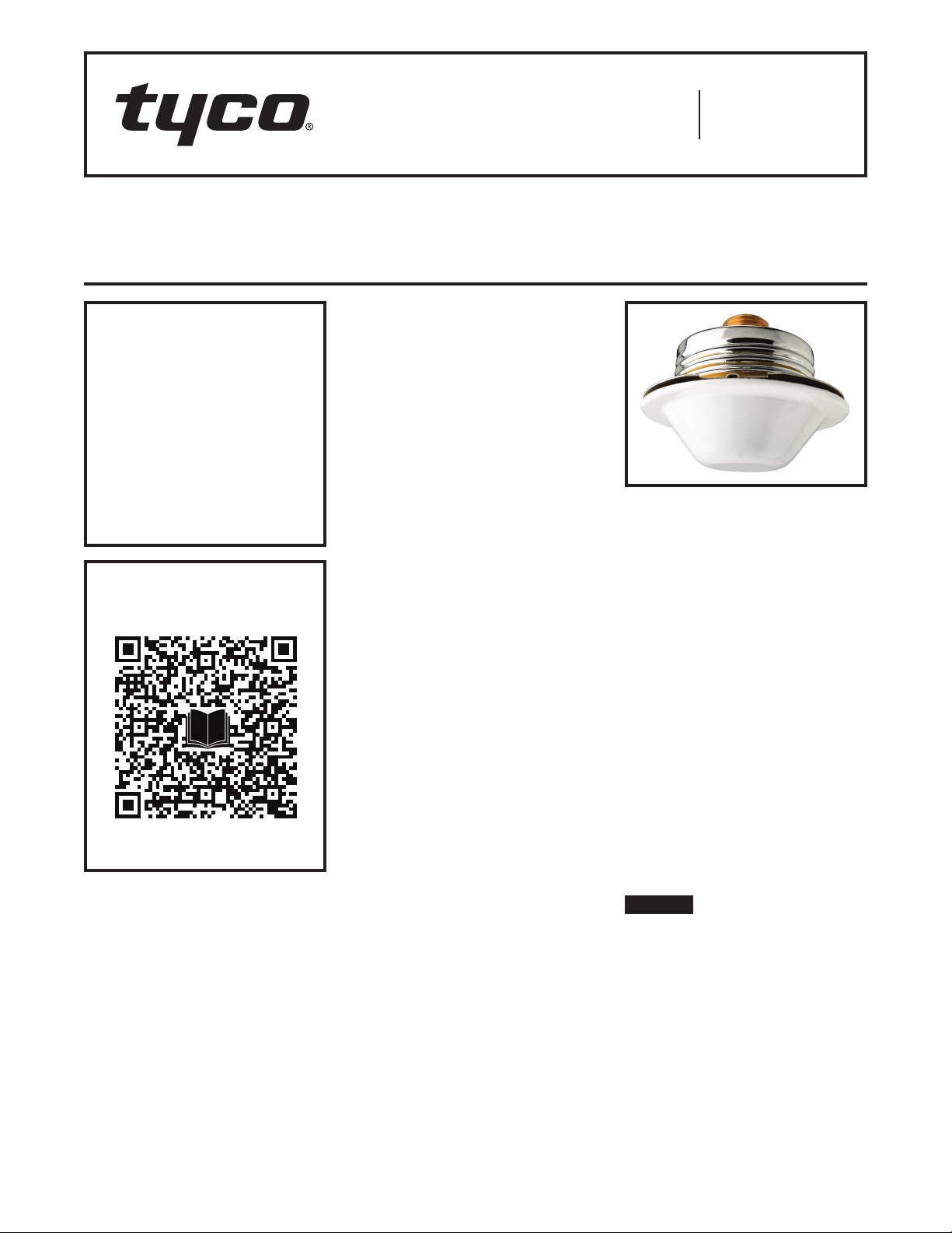
Step 4. Replace the Protective Cap
by pushing it upwards until it bottoms
out against the Support Cup. The Pro-
tective Cap helps prevent damage to
the Deflector and Arms during ceiling
installation and/or during application of
the finish coating of the ceiling. It may
also be used to locate the center of the
clearance hole by gently pushing the
ceiling material against the center point
of the Cap.
As long as the Sprinkler Strap (Figure 1)
or the Protective Cap (Figure 2) remains
in place, the system is considered to be
“Out Of Service.”
Step 5. After the ceiling has been com-
pleted with the 2-1/2 in. (63 mm) diam-
eter clearance hole and in preparation
for installing the Cover Plate/Retainer
Assembly, remove and discard the Pro-
tective Cap and the Sprinkler Strap.
NOTE: Refer to Technical Data Sheet
TFP700 regarding instructions for the
removal of the Sprinkler Strap.
Step 6. Push the Cover Plate/Retainer
Assembly into the Support Cup, and
as necessary, make the final adjust-
ment of the Cover Plate with respect to
the ceiling by turning the Cover Plate/
Retainer Assembly clockwise until its
flange just comes in contact with the
ceiling.
If it becomes necessary to remove
the Cover Plate, it can be removed
by unscrewing in a counter-clockwise
direction.
If the Cover Plate/Retainer Assembly
cannot be engaged with the Support
Cup or the Cover Plate/Retainer
Assembly cannot be engaged suffi-
ciently to contact the ceiling, the Sprin-
kler Fitting must be repositioned.
Care and
Maintenance
The TYCO Series LFII Residential
Domed-Plate Concealed Pendent 4.9
K-factor Sprinklers (TY2234) must be
maintained and serviced in accordance
with this section.
Before closing a fire protection system
main control valve for maintenance
work on the fire protection system
that it controls, obtain permission to
shut down the affected fire protection
systems from the proper authorities
and notify all personnel who may be
affected by this action.
Absence of a Cover Plate may delay
sprinkler operation in a fire situation.
The owner must assure that the sprin-
klers are not used for hanging any
objects and that the sprinklers are only
cleaned by means of gently dusting
with a feather duster; otherwise, non-
operation in the event of a fire or inad-
vertent operation may result.
When properly installed, there is a
nominal 3/32 in. (2,4 mm) air gap
between the lip of the Cover Plate and
the ceiling, as shown in Figure 2. This
air gap is necessary for proper oper-
ation of the sprinkler by allowing heat
flow from a fire to pass below and
above the Cover Plate to help assure
appropriate release of the Cover Plate
in a fire situation. If the ceiling needs
repainting after sprinkler installation,
exercise care to ensure that the new
paint does not seal off any of the air
gap. Failure to do so may impair sprin-
kler operation.
Factory painted Cover Plates must not
be repainted. They should be replaced,
if necessary, by factory painted
units. Non-factory applied paint may
adversely delay or prevent sprinkler
operation in the event of a fire.
Do not pull the Cover Plate relative to
the Retainer. Separation may result.
Sprinklers which are found to be
leaking or exhibiting visible signs of
corrosion must be replaced.
Automatic sprinklers must never be
painted, plated, coated, or otherwise
altered after leaving the factory. Modi-
fied or overheated sprinklers must be
replaced.
Care must be exercised to avoid
damage to the sprinklers - before,
during, and after installation. Sprin-
klers damaged by dropping, striking,
wrench twist/slippage, or the like, must
be replaced. Also, replace any sprinkler
that has a cracked bulb or that has lost
liquid from its bulb. Refer to the Instal-
lation section for additional information.
The owner is responsible for the
inspection, testing, and maintenance of
their fire protection system and devices
in compliance with this document, as
well as with the applicable standards
of the NATIONAL FIRE PROTECTION
ASSOCIATION (e.g., NFPA 25), in addi-
tion to the standards of any authorities
having jurisdiction. Contact the install-
ing contractor or product manufacturer
regarding any questions.
Automatic sprinkler systems are rec-
ommended to be inspected, tested,
and maintained by a qualified Inspec-
tion Service in accordance with local
requirements and/or national codes.
Limited
Warranty
For warranty terms and conditions, visit
www.tyco-fire.com.
Ordering
Procedure
Contact your local distributor for
availability. When placing an order,
indicate the full product name and
Part Number (P/N).
Sprinkler Assembly
Specify: Series LFII (TY2234), K = 4.9,
Residential Domed-Plate Concealed
Pendent Sprinkler without Cover Plate
Assembly, P/N 51-873-1-155
Cover Plate Assembly
Specify: Series LFII (TY2234), K = 4.9,
Residential Domed-Plate Concealed
Pendent Sprinkler Cover Plate Assem-
bly with (specify) finish, P/N (specify):
Pure White*(RAL9010) . . . . . P/N 56-873-3-135
Signal White (RAL9003). . . . . P/N 56-873-4-135
Chrome..................P/N 56-873-9-135
Custom ................. P/N 56-873-X-135
*Eastern Hemisphere sales only.
Sprinkler Wrench
Specify: W-Type 7 Sprinkler Wrench,
P/N 56-850-4-001

TFP450
Page 6 of 6
NATIONAL FIRE PROTECTION ASSOCIATION and NFPA are registered trademarks of National Fire Protection Association;
TEFLON is a trademark of The Chemours Company FC, LLC
1400 Pennbrook Parkway, Lansdale, PA 19446 | Telephone +1-215-362-0700
© 2022 Johnson Controls. All rights reserved. All specifications and other information shown were current as of document revision date and are subject to change without notice.
Other manuals for LFII Series
11
This manual suits for next models
1
Table of contents
Other Tyco Irrigation System manuals

Tyco
Tyco TY-B Series User manual

Tyco
Tyco TY7158 User manual

Tyco
Tyco ESFR-22 User manual

Tyco
Tyco FTR-1 User manual

Tyco
Tyco RAPID RESPONSE Series User manual

Tyco
Tyco ESFR-14 User manual

Tyco
Tyco ESFR-17 User manual

Tyco
Tyco DS-1 Series User manual

Tyco
Tyco EC-5 Series User manual

Tyco
Tyco TFP PH5 Owner's manual