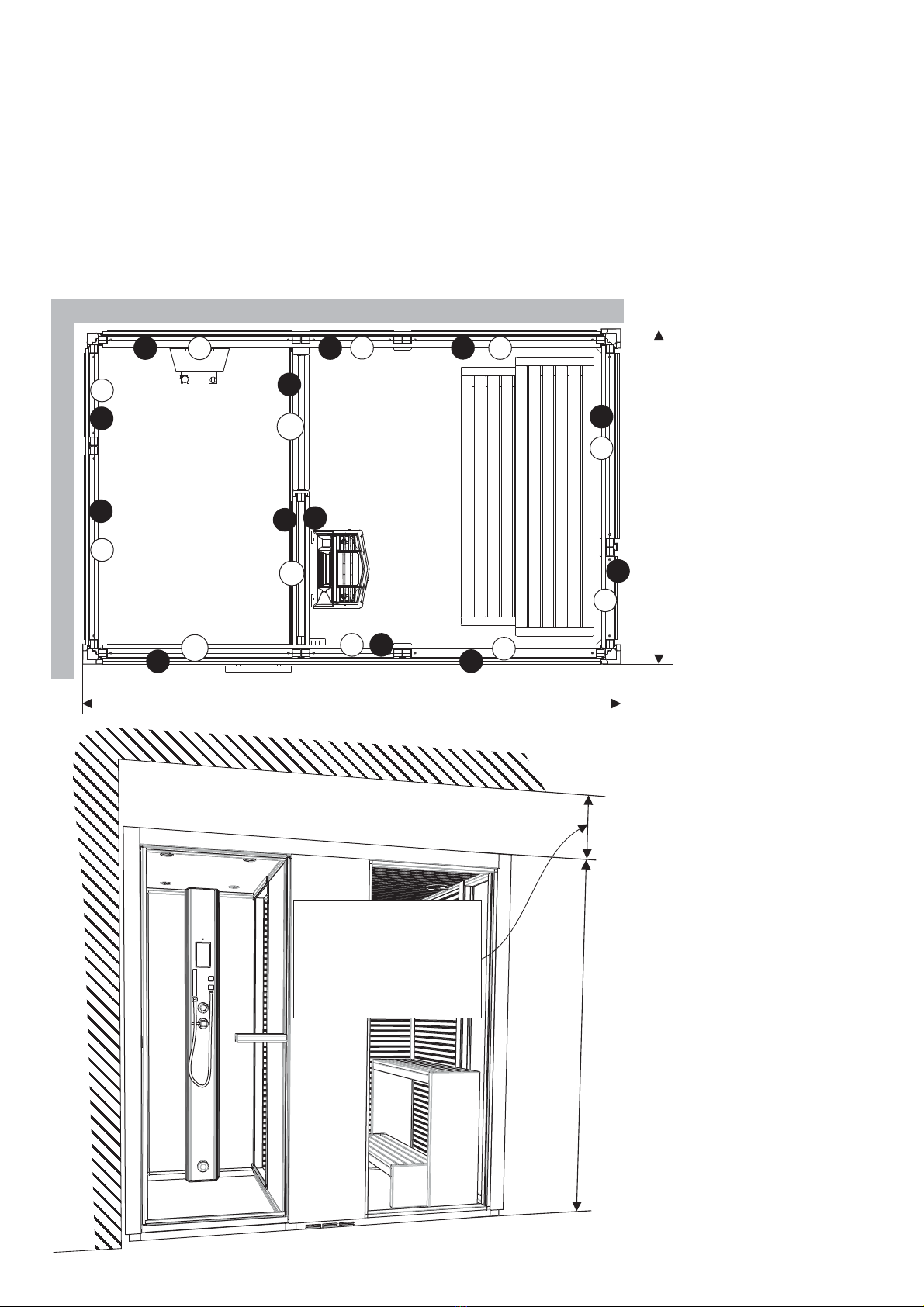
2125 mm
1325 mm
1
2
34
5
6
7
8
9
10
11
12
S
WW
W
P
P
B
P
G
G
D
Layout 1
Configuration 1
Монтажная
схема 1
Układ nr 1
2090 mm
W
W
Det här är ett exempel på montering av rummet. Det är layout 1 som visas i monteringsanvisningen. Ytterligare tre
exempel på montering finns på nästa sida. Siffrorna visar i vilken ordning väggarna skall monteras. Väggarna på
layouten är även märkta med materialet. P= plast, G= glas, B= svart glas, W= Träpanel, D= Glasdörr, S= Glasskjutdörr
The following pictures illustrate just one example of how to assemble the room. These assembly and installation
instructions describe the procedure for assembling Layout 1. On the following page you will find three further examples
of how to assemble the room. The numbers indicate the order in which the walls are to be assembled. The layout
diagrams use the following codes to indicate materials/components: P= plastic, G= glass, B= black glass, W= wooden
panelling, D= glass door, S= sliding glass door
Die Abbildung zeigt eine beispielhafte Montage der Kabine. Die Montageanleitung bezieht sich auf Layout 1. Auf der
nächsten Seite finden Sie drei weitere Beispiele für die Montage. Die Ziffern beziehen sich auf die Reihenfolge, in der die
Wände zu montieren sind. Die Buchstaben bezeichnen das jeweilige Wandmaterial P= Kunststoff, G= Glas, B=
schwarzes Glas, W= Holzvertäfelung, D= Glastür, S= Glasschiebetür
Ceci est un exemple de
montage de la cabine. C'est
la configuration 1 qui est
illustrée par les instructions
de montage. La page
suivante présente trois autres
exemples de montage. Les
chiffres indiquent l'ordre de
montage des cloisons. Sur
l'illustration, les cloisons
portent également une lettre
désignant le matériau. P =
plastique, G = verre, B =
verre fumé, W = panneau de
bois, D = porte vitrée, S =
porte coulissante
Пример монтажа комнаты.
Это монтажная схема 1,
показанная в инструкции по
монтажу. На следующей
странице есть ещё три
примера расположения.
Цифрами показан порядок
монтажа стен. Стенки на
монтажной схеме отмечены
вместе с материалом. P=
пластмасса, G= стекло, B=
чёрное стекло, W=
деревянная панель D=,
стеклянная дверь, S=
стеклянная раздвижная
дверь
Poniższe ilustracje
przedstawiają tylko jeden
przykład aranżacji kabiny.
Poniższa instrukcja montażu i
instalacji opisuje procedurę
dla schematu nr 1. Na
następnych stronach znajdują
się trzy dalsze przykłady
aranżacji kabiny.
Cyfry wskazują kolejność w
jakiej ścianki mają być
montowane. Na schematach
są zastosowane następujące
kody wskazujące
materiały/moduły: P= plastik,
G= szyba, B= czarna szyba,
W= panel drewniany, D=
drzwi szklane, S= drzwi
szklane przesuwane
Min. 250 mm - Vid montering
Min. 250 mm - During
assembly/installation
Mind. 0 mm - Bei Montage25
Mini. 0 mm - Lors du montage25
25 -Мин. 0 мм При монтаже
Min. 100 mm Podczas-
montażu/instalacji


