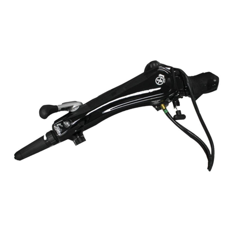
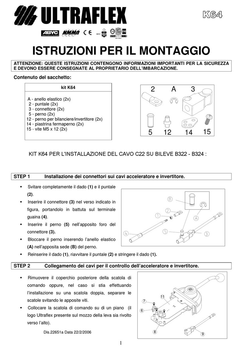
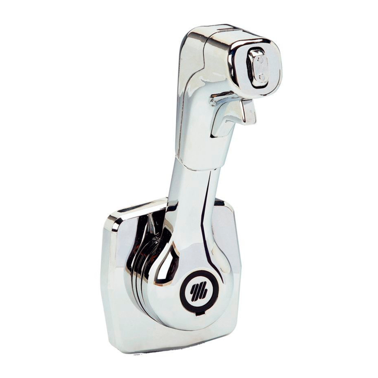
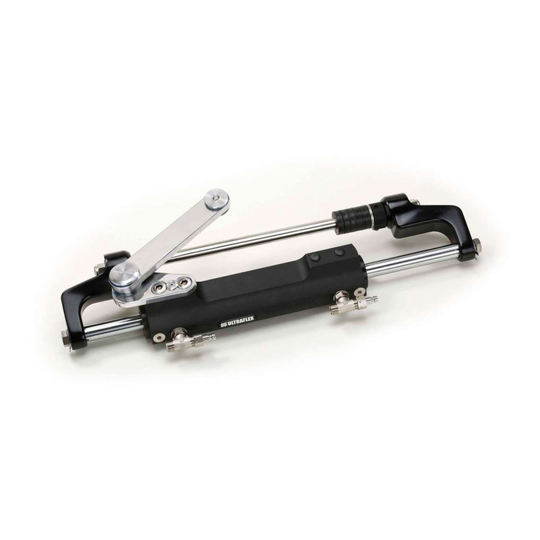
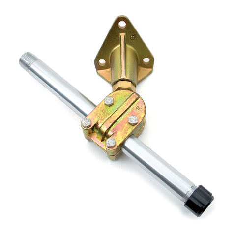
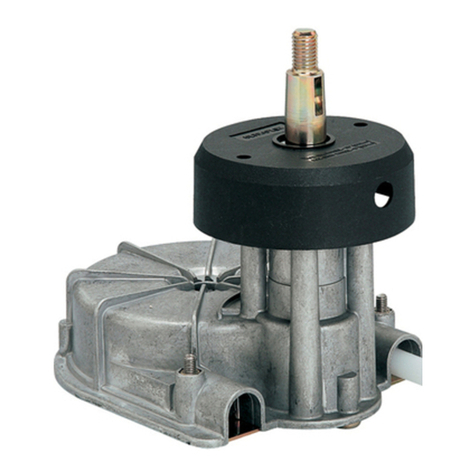
Ultraflex UFLEX ZTF Tiller System KIT QU1 User manual

ZTF
TILLERSYSTEM
Installationmanual
(Dr./Dis./Des. n°34444/a-19/04/2019)

DearCustomer,
TheZTFTiller Systems is produced by UFLEX,amember ofthe ULTRAFLEXGROUP.
ULTRAFLEXGROUP is aleader inmarinesteeringsystemsfor recreationalandcommercialfor more
than85 years.
Ourproductsaredesignedandmanufacturedtoofferthebestperformancewheninstalledandused
properly.
Carefullyread this manualtoensure proper installationanduse ofyour ZTFTiller System.
Serviceshouldbe performed onlybyexperienced andskilled marinetechnicians.
Sarasota,FL34243 -6442 ParklandDrive

ZTF TILLER SYSTEM -page3of27
Installationmanual
TABLEOFCONTENTS
SECTION1-PRODUCTDESCRIPTION
1.1 ZTFTILLER SYSTEMDESCRIPTION......................................................................................................................8
1.2 OPERATING PRINCIPLE..........................................................................................................................................9
SECTION2-TRANSPORT
2.1 GENERAL WARNINGS...........................................................................................................................10
2.2 PACKAGINGCONTENTS..........................................................................................................................10
SECTION3-INSTALLATION
3.1 SAFETY WARNINGS........................................................................................................................12
3.2 INSTALLATIONTYPES.....................................................................................................................12
3.3 INSTALLATION WITH150-175-200 HP YAMAHA®ENGINES...........................................................................13
3.4 INSTALLATION WITH90-115-130 HP YAMAHA®ENGINESFROM2015 TO DATE.......................................17
3.5 YAMAHA®TILLER HANDLE ASSEMBLY.............................................................................................................19
3.6 TILLER HANDLE DISASSEMBLYFROMOUTBOARD ENGINE("REFITTING"INSTALLATION)..................21
3.7 WIRING.....................................................................................................................................................................21
DOCUMENT REVISIONS....................................................................................................................................4
MANUAL USEAND SYMBOLSUSED.............................................................................................................................5
INTRODUCTION LETTER...................................................................................................................................................6
WARRANTY........................................................................................................................................................................6
SECTION5-DISMANTLING
5.1 DISMANTLING.........................................................................................................................................................27
SECTION4-MAINTENANCE
4.1 ORDINARY MAINTENANCE...................................................................................................................................22
4.2 ZTFTILLER SYSTEMFILLING AND PURGING...................................................................................................22

Installationmanual
page4of27-ZTF TILLERSYSTEM
DOCUMENTREVISIONS
Rev.
Dat
e
Rev
ision description
0 25/01/2019 First edition

ZTF TILLER SYSTEM -page5of27
Installationmanual
MANUALUSE AND SYMBOLSUSED
STERN
BOW
STARBOARD PORT Thepictureasideexplainsthemeaningofsome
nauticaltermsincludedinthis manual.
Inthis manualthefollowingiconsareusedtoensuretheusersafetyandtoguarantee thecorrectoperation
oftheproduct:
DANGER ImmediatehazardswhichCAUSEseverepersonalinjuryordeath.
WARNING Hazardsorunsafepractices whichCOULD CAUSEseverepersonalinjury
ordeath.
CAUTION Hazardsorunsafepractices whichCOULD CAUSEminorinjuryordamage
tothecraftorcomponentsortotheenvironment.
Theiconasideindicates all theoperationswhichmustbecarriedoutby
qualifiedorskilledstaff,inordertoavoidhazards.
Werecommendtrainingthestaffinchargeoftheproductinstallation
andcheckingtheirknowledge.
NOTICE Importantinformationforthecorrectinstallationandformaintenance,that
doesnotcauseanydamage.
THEINSTALLATION AND MAINTENANCE MANUAL should bekeptforregularreference bytheownerofthe
boatandtransferedtoanynewownerwiththeboat.
It is necessarytoreadcarefully themanual,beforeANY ACTIVITYinvolvingtheproduct,handlingand
unloadingincluded.

Installationmanual
page6of27-ZTF TILLERSYSTEM
UFLEXUSA,INC.,LIMITEDWARRANTY
1. TwoYearLimitedWarranty. UFLEX USA,Inc.warrantsthatallproductsmanufacturedby UFLEX USA, Inc.
or UFLEX S.p.A. andsold by UFLEX USAtotheretailpurchaser("Purchaser")thatfortwo(2)yearsafterthe
dateofmanufacturetobefree fromdefectsduetomaterialorworkmanship,subjecttotheexclusions
below.ImproperinstallationAVOIDSthiswarranty.Installationshould only beattemptedby atrained
andqualifiedtechnician.
2. Exclusions. This limitedwarrantydoes notcover anddoes notextendtoanyofthefollowing:
(a) Failurecausedbynormalwearandtear,climaticconditions,misuse,neglect,lackofproper
maintenance, accident,fireorothercasualtydamage, racing,overloading,negligence, modification,
beachingorgroundingofvessel,collision,impact,towing,actsofwarorhostilities;
(b)componentsnotmanufacturedby UFLEX USA,Inc.,oritsaffiliates;
(c) costofremovalorreinstallationofanycomponent(includingcomponentsmanufacturedby UFLEX
USA,Inc.)ordisassemblyorreassemblyoftheunitcontainingthecomponent;
(d)componentsnotmanufacturedby UFLEX USA, Inc. or UFLEX S.p.A., whetherornotwarrantedbythe
othermanufacturer;
(e) anyproductwhichhasnotbeenproperlyinstalled.
WARRANTY
TECHNICALASSISTANCE SERVICE
INTRODUCTIONLETTER
North-South-CentralAmerica:
UFLEX USA
6442ParklandDrive
Sarasota,FL34243
Ph.:+1.941.351.2628
Fax: +1.941.360.9171
Email: sales@uflexusa.com
www.uflexusa.com
UFLEX S.r.l.
ViaMiliteIgnoto,8A
16012 Busalla(GE)-Italy
Ph.:+39.010.962.01
Fax: +39.010.962.0333
Email: service@ultraflexgroup.it
www.uflexgroup.it
Thisinstallationandmaintenancemanualis anintegralpartoftheproductandshould beeasilyaccessibletothe
operatorandtheservice technicians.
Theoperatorshould readthis manualanduse theproductonlyforitsintendedpurpose withoutmodification.
UFLEX reservestherighttomodifyanyparts,designdetailsandaccessoriesasitdeemsnecessary to
improvetheproductatanytimewithorwithouttheobligationtomodifythismanualimmediately.
Carehasbeentakenincollectingandcheckingthedocumentationcontainedinthismanualtomakeitas
completeandcomprehensive aspossible.Nothingcontainedinthis manualshouldbeinterpretedas
warrantyeitherexpressedorimpliedbeyondthestatedwarrantybelow.
UFLEX declinesliabilityforanypossiblemistakesinthemanualduetoprintingerrors.
ALLRIGHTSARE RESERVED.Publishingrights,trademarks,partnumbersandphotographsof UFLEX products
containedinthis manualarepropertyof UFLEX.
Toensurethecorrectproductandcomponentoperation,theproductmustbeinstalledbyqualifiedstaff.
Incase ofpartdamageormalfunction,please contactthequalifiedstaff orourTechnicalAssistance Service.
WARNING

ZTF TILLERSYSTEM -page7 of27
Installationmanual
3. Limitations. THEREPAIROR REPLACEMENTOFDEFECTIVE PARTSSHALL BEPURCHASER'SSOLE AND
EXCLUSIVE REMEDY AND UFLEX USA, INC,'SSOLE ANDEXCLUSIVE LIABILITY UNDERTHISWARRANTY.
LABOR FOR REPLACEMENTISNOT INCLUDED. UFLEX USA, Inc.'s obligationunderthis warrantyis limited
totherepairorreplacement(at UFLEX USA, Inc.'s soleelection)ofanycovereditemfoundtobedefective,
whendeliveredbyPurchaserpursuanttowrittenauthorizationandinstructionsfrom UFLEX USA, Inc.,
shippingprepaidto UFLEX USA, Inc.'s plantorotherdesignatedrepairfacility.Repairedorreplaced
itemsarewarrantedasprovidedhereinfortheunexpiredportionoftheapplicablewarrantyperiod.
THISWARRANTY, ANDTHERIGHTSANDREMEDIESUNDERIT, ISEXCLUSIVE ANDISGIVENINPLACE OF
ALLOTHERWARRANTIES,WHETHEREXPRESSOR IMPLIED, INCLUDINGANYIMPLIEDWARRANTYOF
MERCHANTABILITYOR FITNESS FOR PARTICULARPURPOSE,WHETHERARISINGBY LAW,CUSTOM,
CONDUCTOR USAGEOFTRADE,PURCHASER'SREMEDIESSHALL BELIMITEDASSTATEDHEREINAND
UFLEX USA, INC.SHALL NOT BELIABLE FOR ANYINCIDENTAL,CONSEQUENTIALOR INDIRECTDAMAGES
OR LOSSESRESULTINGFROMDEFECTS.THERETAILSELLERISNOT ACO-WARRANTOR ANDISNOT
AUTHORIZEDBY UFLEX USA, INC.TO AMENDOR MODIFYTHISLIMITEDWARRANTY INANYMANNER.
4.TransferabilityofWarranty. Thislimitedwarrantymaynotbetransferredtosubsequentpurchasers.
5. Miscellaneous. UFLEX USA,Inc.isanaffiliateof UFLEX S.p.A. UFLEX,USA, Inc.,reservestherighttomake
changes inthe designandconstructionofits products atanytime, withoutnotice andwithoutanyobligation
toincorporatesuchchangesintoproductsofpriormanufacture.Thislimitedwarrantyappliestonew
componentssold by UFLEX USA, Inc.. This limitedwarrantycontainstheentireagreementsbetween
UFLEX USA,Inc.andPurchaserandsupersedes allprioragreements,discussions,negotiations,
commitmentsandrepresentations,whetheroralorwritten,betweenthemregarding UFLEX USA,Inc's
warranty.If anyprovisionofthis limitedwarranty,ortheapplicationofit,is determinedtobeinvalidof
unenforceableforanyreason,theremainderofthislimitedwarrantyandtheapplicationofitshall not
beaffected.
AllcommunicationsandnoticesfromPurchaserregardingthis limitedwarrantyshould besentto:
Returnpolicy
Anyproductthatis presumeddefectiveshould bereportedto UFLEX USAwithin48hoursofreceiptor
discoveryinthefield.Uponnotification UFLEX USAwill attempttotroubleshoottheproblemwithourcustomer
overthephone. If weareunabletoresolvetheproblem UFLEX willissueaReturnGoodsAuthorization
numberandwerequirethattheproductinquestionbereturnedto UFLEX withallitspartsinitsoriginal
packaging.Theproductshouldbereturnedfreightprepaidto:
UFLEXUSA
RGA Department-RGA #
6442 ParklandDrive
Sarasota,Florida34243
Uponreceipt UFLEX will examinetheproducttodeterminethecause ofthedefect.If theproductis determined
tohaveadefectinworkmanshipormaterial,itwill berepairedatourdiscretion.
Ourwarrantydoes notcoverlabor,towingorotherexpenses. Further,itdoes notcoverproductsthathave
beenimproperlyinstalled,damagedininstallation,misapplied,ormisused.
Ourproductsarenotintendedforuseinracingapplications.
UFLEXUSA,INC.
6442 ParklandDrive
Sarasota,Florida34243
(941)351-2628
Installationmanual
page8of27-ZTF TILLERSYSTEM
1PRODUCTDESCRIPTION
1.1ZTFTillerSystemdescription
TheZTFTillerSystemis ahydraulic device thatneutralizes thepropellertorqueofoutboard engines onthe
tillerhandlewhiletheoperatorisnotactivelymakingasteeringcoursechange.It enables theoperatorto
maintainthedesiredcourse withoutexcessive physicaleffort.
Thehydraulicvalve opensthemomenttheoperatormakesasteeringcourse changeatwhichpointthe
propellertorquewill bepresentonthetillerhandle. It is importantthattheoperatormaintainsafirmgrip
onthetillerhandleatall times whileoperatingtheboat;especiallywhenmakingsteeringcourse changes.
TheZTFTillerSystemconsistsoffourmaincomponents:
Tillerhandle(supplieddirectlybyYamaha®oroneofitsresellers)
Maindevice
UC130ZTFhydrauliccylinder
Hydraulichoses
1
2
3
NOTICE
TheZTFTillerSystemis alwayssuppliedoil-filled,purged,functioningandwithproperlyconnectedhoses.
Avoidtwisting,damaging,bendinganddisconnectingthehoses.
CAUTION
TheZTFTillerSystemmustbeusedcombinedwith Yamaha®outboard engines of90-115-130 HP produced
from2015 todate, andengines of150-175-200 HP -models2.7L F150 Mechanical,VF150 VMAXSHO, F175,
VF175 VMAXSHO, andF200 Mechanical- andmustbeassembledonly onboatsspecificallydesignedand
suitablyequippedforbeingsteeredwiththetillerhandle. Theinstallerandtheoperatorareresponsiblefor
ensuringtheproperfunctioningoftheZTFTillerSystemontheboat,bearinginmindfactorslikespeed,
motorloadsandworkingconditions.
CAUTION
Forinstallationsotherthantheonesrequiredforabove-mentionedYamaha® engines,pleasecontact UFLEX
TechnicalAssistanceService.
CAUTION
Do notuse this device forpurposes otherthanthose itwas madefor,as specifiedintheinstallationmanual.
1
4
423
CAUTION

ZTF TILLER SYSTEM -page9of27
Installationmanual
1.2Operatingprinciple
Thepatentedhydraulic valve andcorrespondingcylinderoftheZTFTillerSystemopensandcloses incase
theoperatorpushes orpullsthetillerhandle. Whentheoperatorneitherpushes norpullsthetillerhandle
(changingsteeringcourse),thehydraulicvalve closes eliminatingthesteeringloadfrompropellertorque
onthetillerhandle.
TheoperatorMUSTmaintainafirmgriponthetillerhandleunderALL operatingconditions; whileactively
changingcourseorwhilemaintainingafixedcourse(withvalve closed) asseaconditions,floatingdebris,
orotherconditionscould changethesteeringcoursewithoutinputdirectly fromtheoperator.
TheZTFTillerhas aBy-Pass Knobunderneaththeprimary
assemblythatcanbeusedtoengageordisengagethe
hydraulicvalve. Turningtheknobclockwise completely will
activatetheZTFvalve -lockingoutthepropellertorquewhile
notactively changingsteeringcourse. Turningtheknob
counter-clockwise willdisengagetheZTFTillervalve which
will allowthepropellertorquetoreachthetillerhandle-
evenwhennotactively makingasteeringcoursechange.
It is essentialthattheoperatorconfirmsthefunctionalityand
statusoftheZTFTillerSystembeforeeachuse.
To determinewhetherthesystemis active andfunctional,
firstcheck toensurethattheBy-PassKnobisfirmlyclosed
byturningtheBy-pass Knobclockwise.Thenfirmlypushon
thebackoftheenginetosimulateasteeringchange(withoutpushingonthetillerhandlesimultaneously).
If theenginedoes notturnineitherdirection,theZTFis engaged.
If theenginemoves,tightentheBy-PassKnobintheclockwise directionandcheckagaintoseeifthe
enginemoves. If itcontinues tomove,donotuse theboatandcontactyourdealerof UFLEX fortechnical
support.
Internalvalve
open Internalvalve
open Internalvalve
closed
Propellertorque
Noeffort
=
Zerotorque
feedback
Propellertorque Propellertorque
WARNING
ZERO
TORQUE
FEEDBACK
OFF
ZERO
TORQUE
FEEDBACK
ON

Installationmanual
page10of27-ZTF TILLERSYSTEM
1.Bracket
2.Hardwarefasteningthedevicetothebracket
(2screwsM12,2nuts, 4washers)
3.Hardwarefasteningthecylinderlinkarmtothe
enginearm(2specialboltsULTRABOLT, 2high
nuts, 4washers)
4.Hardwarefasteningthecylinderlinkarmtothe
enginearm(1SVS boltULTRABOLT, 1SVS
washer, 1thinnut)
5.Hardwarefasteningthebracket totheengine
arm(2pivots,2washers,2nuts)
CAUTION: thishardwareisalwaysincludedin
Yamaha®tillerhandles
KITQU1
(150-175-200 HPENGINES)
KITND1
(90-115-130HPENGINESFROM
2015)
2.1Generalwarnings
2TRANSPORT
Theproductweightwithitspackagingis 20kg (44lbs.).Therefore, itcanbehandledmanually.
2.2Packagingcontents
Beforeusingtheequipmentcheckthattheproducthasnotbeendamagedduringtransport.Also
makesurethatall thestandardcomponentsareinthepackaging.Incaseofdamage,donotuse the
ZTFTillerSystemandnotifythefreightcarrierandyourdealer/distributorimmediately.
TheZTFTillerSystemis providedwiththefollowingitems:
WARNING
Thestaffinchargeofhandlingmustoperatewithprotectivegloves andsafetyshoes.
12
3
Yamaha® tillerhandle
Maindevice
Accessory kitbasedoninstallationtype,providedseparately (see thefollowingtablewithrelated
drawingsandparagraph3.2)
IfYamaha®tillerhandle is new,itwill
alwaysbe supplied with original bracket
and the required fastening screws.Itwill
be necessarytoremovethe original
bracket in ordertoinstall the ZTFsystem.
NOTICE
ORIGINAL
BRACKET

ZTF TILLER SYSTEM -page11of27
Installationmanual
KITQU1 KITND1
1
2
34
5
1
2
Thepackaging mustbe disposed ofaccordingtothe existinglaws.
CAUTION

Installationmanual
page12of27-ZTF TILLERSYSTEM
3INSTALLATION
3.2Installationtypes
TheZTFsystemhastwodifferentinstallationtypes:
1)NEWINSTALLATION: TheCustomerpurchasesanewYamaha®tillerhandleor,moregenerally,the
possessedtillerhandlehasneverbeeninstalledontheoutboardengine.
2)REFITTING: TheCustomer'sYamaha®tillerhandlehasbeenalreadyinstalledontheoutboardengine.
Moreover,theinstallationprocedurevariesaccordingtothetypeofYamaha®outboardengineonwhich
theZTFsystemisinstalled,asdescribedinthefollowingscheme:
3.1Safetywarnings
Strictlyfollowtheprecautionsandthesafetywarningsthroughoutthis entiremanual.Failuretodoso could
resultinlossofsteeringwithpossibledamage, injuriesanddeath.
UFLEX declinesallresponsibilityforerrorsduringinstallation,mis-application,mis-use,neglect,orlackof
maintenanceorroutineinspection.
-DONOTPUTHANDSBETWEENTHEMOVINGPARTS.
-Donotdisableinanyway thesafetydevices.
-Do notmodifyoradddevices tothesystem,without UFLEX writtenauthorizationortechnical intervention
whichwill prove themodification.
-Installationshould only beperformedby wellexperienced andtrainedmarinetechnicians.
PERICOLO
DANGER
NEWINSTALLATION
(theCustomerpurchasesa
newtillerhandleorthe
possessedtillerhandlehas
neverbeeninstalledon
theoutboardengine)
REFITTING(theCustomer's
tillerhandlehasbeen
alreadyinstalledonthe
outboardengine)
TYPEOFOUTBOARD
ENGINE
ENGINETYPE
90-115-130 HPFROM2015
ENGINETYPE
150-175-200 HP
USEOFKITQU1 USEOFKITND1
FOLLOWTHE
INSTALLATION
INSTRUCTIONSFOR200
HPENGINES(seepar.3.3)
FOLLOWTHE
INSTALLATION
INSTRUCTIONSFOR130
HPENGINES(seepar.3.4)
TILLERHANDLEASSEMBLY
(seepar.3.5)
CONNECTINGSHIFTAND
THROTTLECABLES
(seepar.3.7)
INSTALLATION
TYPE
Dismantlingthetiller
handlefromtheoutboard
engine(seepar.3.6)

ZTF TILLER SYSTEM -page13of27
Installationmanual
1 Fastenbracket(1)ondevice (2)usingscrews (3)andnuts (4)afterhavingproperly placedwashers
(5).Lockusing218mm wrenches withatighteningtorqueof80 Nm(59 lb.-ft.).
3.3Installationwith150-175-200HPYamaha®engines
As reportedonthepreviouspages, theZTFinstallation
with150-175-200HP enginesrequirestheuseofKIT
QU1 (see also par.2.2).
NECESSARYTOOLS
(2x)Openend
wrench
18mm
Torquewrench
MOLYKOTE® 1000
CAUTION
Applygrease tothescrewshaftsbeforetighteningthenuts.
Thebracketmustbeorientedasshown inthepicture.
KIT
QU1 1
4
5
3
6
7
10
14
11
13
8
1
2
3
4
5
Openend
wrench
9/16"
CAUTION

Installationmanual
page14of27-ZTF TILLERSYSTEM
2Place thetwoultrabolts(6)and(7)withwashers(8)intotheenginearm(9)uptohalf oftheirlength.
Thescrewsmustprotrudefromtheenginearmbyaround15mm.
NOTICE
7
6
8
9
3Assemblethedevicewith
bracket(1)ontheenginearm(9).
Becarefulnottobend,kinkor
disconnecthydraulichoses.
4Place washer(10)onthefront
ultrabolt (6),whichistheclosest
tothedevice andtightenmanually
theself-lockingnut(11).
Apply grease tothescrewshafts
beforetighteningthenuts.
19
6
10
11
CAUTION
CAUTION

ZTF TILLER SYSTEM -page15of27
Installationmanual
5Placethecylinderlinkarm
(12)ontherearscrew(7).
Inordertocompletethefaste-
ningprocess ofthecylindertothe
enginehose,refertothe
instructionscontainedinthe
manualofthecylinder.
NOTICE
12
7
6Screwultrabolt(7)lettingit
protrudefromthecylinderlink
armby atleast5mm,thenplace
washer(13)(seepicturebelow).
7Manuallytightentheself-
lockingnut(14)onscrew(7).
Apply grease tothescrewshaft
beforetighteningthenut.
7
14
7
13
CAUTION

Installationmanual
page16of27-ZTF TILLERSYSTEM
This check requires careful attention.
This operationrequires careful attention.
8Bringthetwoultraboltsintocontactwith
theenginetillerarmandfastenthemusinga
9/16"wrenchwith atorqueof54 Nm(40 lb.-
ft.).
CAUTION
9Afterwards, whileholdingascrewwith
a9/16"wrench,fastenthecorrespondingnut
withatorqueof54Nm(40lb.-ft.).Repeatthis
operationontheothernutalwaysbyholding
itsscrew.
Double-checkthetighteningofscrewsand
nutsbyrepeatingthesameprocedure
describedinpoints8and9(fasteningscrews
andnutswhileholdingscrews).
CAUTION
10 CompletetheassemblyofUC130 cylinder onthe outboard enginefollowingwhatis reported on
theinstallationandmaintenancemanualofthecylinder itself,exceptfor thefasteningphase ofthe
cylinder linkarmtotheenginearm,whichis described inthepreviouspoints.
Do notdisconnectthehydraulichoses for anyreason.
11 AssembleYamaha®tiller handleontheZTFdeviceas described inparagraph3.5.
NOTICE

ZTF TILLER SYSTEM -page17of27
Installationmanual
Thebracketmustbeorientedasshown inthepicture.
Applygrease tothescrewshaftsbeforetighteningthenuts.
3.4Installationwith90-115-130HPYamaha®enginesfrom2015todate
Asreportedonthepreviouspages,theZTFinstallation
with90-115-130 HP engines from2015 requires theuse
ofKITND1 (see also par.2.2).
1Fastenbracket(1)ondevice (2)usingscrews(3)andnuts(4)afterhavingproperlyplacedwashers
(5).Lockusing218mm wrenches withatighteningtorqueof80 Nm(59 lb.-ft.).
NECESSARYTOOLS
2Screwandlockthestuds(7)totheenginearm(6)
followingthetighteningtorqueandtheinstructions
containedinthemanualofYamaha® tillerhandle.
(2x)Openend
wrench
18mm
Torque
wrench
MOLYKOTE® 1000
CAUTION
CAUTION
1
2
3
4
5
KITND1 1
354
7
910
11
Openend
wrench9/16"
Openend
wrench
14mm
7
6

Installationmanual
page18of27-ZTF TILLERSYSTEM
4 Fastenthecylinderlinkarm(8)totheenginearm(6)byscrewinga3/8"ultrabolt(9)intheclosest
holetothestern,byinterposingwasher(10):tightentheultrabolt usinga14 mm wrenchwithatorqueof
54 Nm(40 lb.-ft.).
Screwtheself-lockingnut(11)with
a9/16"wrenchandtightenitwith
atorqueof27 Nm(20 lb.-ft.).After
havingfastenedthenut(11),
recheck thatthetighteningtorque
-54Nm(40 lb.-ft.)-ofthescrew
(11)is correct.
Applygrease tothescrewshafts
beforetighteningthenuts.
5Complete the assemblyofUC130 cylinder onthe outboard engine byfollowingwhatis reported
ontheinstallationandmaintenancemanualofthe cylinder itself,exceptfor thefasteningphase of
thecylinder linkarmtotheenginearm,whichis described inthepreviouspoints.
Do notdisconnectthehydraulichoses for anyreason.
6Assemblethetiller handleontheZTFdeviceas described inparagraph3.5.
CAUTION
3Fastenthedevicewiththebracketontheenginearmusingnuts(X)andinterposingwashers(Y),
followingthetighteningtorqueandtheinstructionscontainedinthemanualofYamaha® tillerhandle.
Applygrease tothepivotsbeforetighteningthenuts.
Duringthisoperation,becarefulnottodamage,bendanddisconnectthehydraulichoses.
CAUTION
NOTICE
X
Y
8
6
10
9
11

ZTF TILLER SYSTEM -page19of27
Installationmanual
Ifthese componentsaredamaged,theymust
bereplaced.Inthis case, contactthetechnical
assistance.
3.5Yamaha®tillerhandleassembly
TheYamaha®tillerhandleis composedofthemainbody
(1)andtheoriginalbracket(2)forconnectingittothe
enginearm.
InordertoinstallthetillerhandleontheZTFdevice, it
is necessary toremove bracket(2)andassemblethe
mainbody(1)directlyontheZTFdevice.
To this end,refertowhatisreportedinfollowing
paragraphs.
1Inordertoinstallthetillerhandleonthe
ZTFdevice, itisnecessarytoremovethe
originalbracket,takingcarenottodamage
thescrew,thebushings, thewashersandthe
connectingnut.Becarefultothepositionof
these parts, since they will beusedagainfor
assemblingthemainbodyofthetillerhandle
tothedevice.
3.5.1 Originalbracketremoval
Duringdisassembly,ALL componentsmust
beremoved,sincetheywill bereusedforthe
followingreassembling.
NOTICE
CAUTION
1
2

Installationmanual
page20of27-ZTF TILLERSYSTEM
3.5.2 ZTFdeviceassemblyontillerhandle
1Themainbodyofthetiller
handlemustbefastenedtothe
device inlinewiththefork.
Fastenthetillerhandle(1)todevice
(2),takingcareofpositioning
bushings, spacersandwashersas
shown inthepictureaside(following
thesameorderinwhichtheywere
disassembled).
Afterhavinglubricatedbolt(3),fasten
nut(4)withatighteningtorque
between29.4 and34.3 Nm(from
21.68to25.29lb.-ft.),avoiding
excessiveplayofthehandle
allowingitstilttoanyangle.
Checkthattheupwardand
downwardmovementsoftiller
handlearecorrectandthereisno
free play alongthehorizontalaxle,
enablingtheproperfunctioningof
thedevice.
Applygreasetothescrewshafts
beforetighteningthenuts.
1
2
3
4
CAUTION
This manual suits for next models
1
Table of contents
Other Ultraflex Boating Equipment manuals

Ultraflex
Ultraflex ZTF Tiller System User manual

Ultraflex
Ultraflex K18 User manual

Ultraflex
Ultraflex UC 130 Manual

Ultraflex
Ultraflex UC 95 User manual

Ultraflex
Ultraflex B 310 Manual

Ultraflex
Ultraflex UC 81 Manual

Ultraflex
Ultraflex A97 Manual

Ultraflex
Ultraflex OB/R5 User manual

Ultraflex
Ultraflex UC130-SVS Manual

Ultraflex
Ultraflex T93ZT Manual
Popular Boating Equipment manuals by other brands

Garelick
Garelick 19250 installation instructions

Classic Accessories
Classic Accessories Stellex instructions

Thrane&Thrane
Thrane&Thrane SAILOR 500 FleetBroadband user manual

Harken
Harken 32 mm Big Boat instructions

NUCANOE
NUCANOE 3005 Assembly instructions

Wichard
Wichard Gyb'Easy Recommended installation