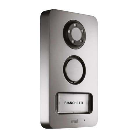
urmet domus 2VOICE MIKRA2 1784 Quick start guide

DS 1784-001 LBT 20578
Mod.
1784
PULSANTIERA MIKRA2 2VOICE 1 TASTO / 2 TASTI
MIKRA2 2VOICE 1 BUTTON / 2 BUTTON CONTROL PANEL
CLAVIER MIKRA2 2VOICE 1 TOUCHE / 2 TOUCHES
TECLADO MIKRA2 2VOICE 1 PULSADOR / 2 PULSADORES
TASTENFELD MIKRA2 2VOICE 1 TASTE / 2 TASTEN
DEURPLAAT MIKRA2 2VOICE 1 TOETS / 2 TOETSEN
Sch./Ref. 1784/1 - 1784/2
LIBRETTO INSTALLAZIONE E UTENTE
INSTALLATION AND USE BOOKLET
NOTICE D’INSTALLATION ET UTILISATEUR
MANUAL DE INSTALACIÓN Y DE USO
INSTALLATIONS- UND BENUTZERANLEITUNG
INSTALLATIE- EN GEBRUIKSAANWIJZINGEN
IP55
IK07

2DS1784-001
ITALIANO
INDICE
1 DESCRIZIONE GENERALE ..................................................................................................................... 2
2 DESCRIZIONE DEI COMPONENTI ......................................................................................................... 3
3 INSTALLAZIONE ..................................................................................................................................... 4
3.1 MODALITA’ DI INSTALLAZIONE .................................................................................................... 4
3.2 DESCRIZIONE DEI MORSETTI....................................................................................................... 5
3.3 CONFIGURAZIONE......................................................................................................................... 5
3.3.1 Impostazioni SW4................................................................................................................. 5
3.3.2 ImpostazionI SW3................................................................................................................. 6
3.3.3 ImpostazionI SW2................................................................................................................. 7
3.3.4 Rotary switch SW1 ............................................................................................................... 7
3.3.5 Valori di default..................................................................................................................... 8
3.3.6 Regolazione livello fonico altoparlante ................................................................................. 8
4 SEGNALAZIONI FUNZIONI DDA............................................................................................................. 9
5 AZIONAMENTO ELETTROSERRATURA PEDONALE............................................................................. 9
6 AZIONAMENTO ELETTROSERRATURA PASSO CARRAIO................................................................... 9
7 CARATTERISTICHE TECNICHE.............................................................................................................. 9
8 ALCUNE TIPOLOGIE DI IMPIANTO...................................................................................................... 10
9 SCHEMI DI COLLEGAMENTO.............................................................................................................. 68
9.1 NOTE LEGATE AGLI SCHEMI ...................................................................................................... 68
9.2 LEGENDA...................................................................................................................................... 74
ENGLISH ................................................................................................................................................. 13
FRANÇAIS .............................................................................................................................................. 24
ESPAÑOL................................................................................................................................................ 35
DEUTSCH ............................................................................................................................................... 46
NEDERLANDS...................................................................................................................................... 57
1 DESCRIZIONE GENERALE
Le pulsantiere Mikra2 Sch. 1784/1 e 1784/2 sono dedicate al sistema 2Voice. Possono essere utilizzate ad
esempio in impianti kit monofamiliari o bifamiliari, oppure in impianti estesi come postazioni di chiamata
secondarie. Le caratteristiche principali sono:
Pulsantiera antivandalo con frontale in zama resistente agli agenti atmosferici.
Telecamera della pulsantiera a colori con ampio angolo di ripresa (wide-angle) e illuminazione del
soggetto mediante led.
Cartellino portanome e pulsante di chiamata retroilluminato con led bianchi.
Segnalazione visiva e acustica dello stato dell’impianto (DDA), funzione disponibile solo con pulsantiera
monofamiliare (Sch. 1784/1).
Predisposizione per il collegamento del sensore dedicato alla funzione STATO PORTA oppure
LETTERBOX (futura implementazione).
Riscontro sonoro di invio della chiamata.
Predisposizione per dispositivo di ripetizione della fonia per audiolesi (Modulo ILA) Sch. 1723/48.
•
•
•
•
•
•
•
3
DS1784-001
2 DESCRIZIONE DEI COMPONENTI
VISTA FRONTALE
Pulsantiera con 1 tasto di Pulsantiera con 2 tasti di
Chiamata Sch. 1784/1 Chiamata Sch. 1784/2
1
2
3
1
2
3
4
6
7
8
4
5
6
7
8
1. Altoparlante
2. Led di illuminazione telecamera
3. Telecamera
4. Cartellino/i portanome
5. Segnalazioni led dedicate alla funzione DDA (Sch. 1784/1)
6. Pulsante/i di chiamata
7. Microfono
8. Vite di chiusura frontale
PARTE INTERNA
15
16 J3
9
10
14
13
12
11
9. Dip-switch di configurazione
10. Rotary switch
11. Morsettiere
12. Foro per passaggio cavi
13. Trimmer regolazione volume altoparlante
14. Non ruotare questo trimmer
15. Guarnizione antiriflesso
16. Connettore per predisposizione ILA (J3)

4DS1784-001
3 INSTALLAZIONE
3.1 MODALITÀ DI INSTALLAZIONE
Installare la pulsantiera all’altezza indicata verificando che il soggetto rientri nel campo inquadrato dalla
telecamera.
Collegare i fili alle morsettiere.
Montare i cartellini portanome sul frontale.
Eseguire le programmazioni.
Chiudere la pulsantiera con la copertura metallica.
Rimuovere le pellicole di protezione.
Campo di ripresa verticale Campo di ripresa orizzontale
(*) Nel caso di persone con disabilità o specifiche necessità di tipo D1 (con età avanzata) e D2 (con difficoltà
motoria degli arti inferiori), il centro del dispositivo dovrà essere posizionato ad una altezza compresa
tra 75 cm e 140 cm rispetto al piano di calpestio. Per ulteriori dettagli vedere la Norma tecnica CEI
64-21:2016-12 – Ambienti residenziali. Impianti adeguati all’utilizzo da parte di persone con disabilità o
specifiche necessità.
•
•
•
•
•
•
~146 cm
~100 cm
110°Max.
92°Max.
~100 cm
~100 cm~100 cm
~146 cm
155÷160 cm(*)
1
2
4 5
3
6
100 mm
180 mm
28 mm

5
DS1784-001
3.2 DESCRIZIONE DEI MORSETTI
Morsettiera sinistra
SE- Morsetti elettroserratura pedonale con scarica capacitiva
SE+
PA Ingresso per pulsante serratura elettrica pedonale
SP Ingresso (riferimento) per sensore normalmente chiuso dedicato alla funzione STATO
PORTA oppure LETTERBOX.
Morsettiera destra
SP Ingresso (segnale) per sensore normalmente chiuso dedicato alla funzione STATO
PORTA oppure LETTERBOX.
LINE Morsetti collegamento BUS
N.O. Morsetti elettroserratura passo carraio
3.3 CONFIGURAZIONE
SW1
SW2
SW3
SW4
= =
ON
ON
3.3.1 Impostazioni SW4
21 43
ON
65
21 43
ON
65
21 43
ON
65
21 43
ON
65
21 43
ON
65
21 43
ON
65
21 43
ON
65
21 43
ON
65
21 43
ON
65
21 43
ON
65
21 43
ON
65
21 43
ON
65
Principale
Secondaria 0
Apriporta
sotto segreto
Non abilitata
Accensione
led telecamera
attivata
Monofamiliare
Secondaria
Secondaria 1
Apriporta
libero
Abilitata
Accensione
led telecamera
disattivata
Bifamiliare
Dip 1 Tipo di postazione
Dip 2 Indirizzo postazione
di chiamata
secondaria
Dip 3 Apriporta
Dip 4 Interruzione
Dip 5 Accensione
led telecamera
Dip 6 Numero utenti
Tipo di postazione (dip-switch 1): il posto esterno può essere configurato come principale o come secondario.
Dal posto esterno principale è possibile chiamare tutti gli utenti dell’impianto, dal posto esterno secondario

6DS1784-001
è possibile chiamare solo gli utenti della colonna di appartenenza. L’utente che riceve la chiamata è in grado
di distinguerne la provenienza dalla temporizzazione con cui viene emesso lo squillo.
Indirizzo postazione di chiamata secondaria (dip-switch 2): in una stessa colonna possono essere presenti
2 postazioni di chiamata secondarie che devono avere numero diverso.
Apriporta (dip-switch 3): l’elettroserratura può essere gestita in modalità “sotto segreto” o “libero”’. Il
comportamento del posto esterno è il seguente nei due casi:
“Sotto segreto”: la pressione del pulsante apriporta di un posto interno può attivare l’elettroserratura
della postazione di chiamata solo se ha ricevuto una chiamata o è in conversazione fonica con essa o
anche se, in seguito ad autoinserzione, è comunque in connessione video con essa.
“Libero”: la pressione del pulsante apriporta di un posto interno può attivare l’elettroserratura del posto
esterno solo se il posto esterno è configurato come principale o l’utente appartiene alla colonna dello
stesso posto esterno secondario. Tale colonna è definita dalla impostazione dell’ID del posto esterno
secondario. La prestazione è usata tipicamente sulle postazioni secondarie.
Interruzione (dip-switch 4): quando è in corso un’autoinserzione o una conversazione intercomunicante la
colonna interessata o l’intero sistema è in stato di occupato. Lo stato di occupato può essere, a seconda
della configurazione di questo switch, interrotto da una chiamata dal posto esterno oppure no.
Il parametro “Interruzione” deve essere programmato nello stesso modo su tutte le postazioni di
chiamata presenti nell’impianto.
Accensione led telecamera (dip-switch 5): è possibile disattivare l’accensione dei led della telecamera
laddove l’illuminazione notturna dell’ambiente circostante sia ritenuta sufficiente.
Numero utenti (dip-switch 6): monofamiliare (1 tasto) se pulsantiera Sch. 1784/1, bifamiliare (2 tasti) se
pulsantiera Sch. 1784/2.
Il parametro “Numero utenti” non deve mai essere modificato.
3.3.2 Impostazioni SW3
ID
ON DIP
43215
ID=0
ON DIP
43215
ID=1
ON DIP
43215
ID=2
ON DIP
43215
ID=3
ON DIP
43215
ID=4
ON DIP
43215
ID=5
ON DIP
43215
ID=6
ON DIP
43215
ID=7
ON DIP
43215
ID=8
ON DIP
43215
ID=9
ON DIP
43215
ID=10
ON DIP
43215
ID=11
ON DIP
43215
ID=12
ON DIP
43215
ID=13
ON DIP
43215
ID=14
ON DIP
43215
ID=15
ON DIP
43215
ID=16
ON DIP
43215
ID=17
ON DIP
43215
ID=18
ON DIP
43215
ID=19
ON DIP
43215
ID=20
ON DIP
43215
ID=21
ON DIP
43215
ID=22
ON DIP
43215
ID=23
ON DIP
43215
ID=24
ON DIP
43215
ID=25
ON DIP
43215
ID=26
ON DIP
43215
ID=27
ON DIP
43215
ID=28
ON DIP
43215
ID=29
ON DIP
43215
ID=30
ON DIP
43215
ID=31
Impostare un numero (ID) da 0 a 3 se il posto esterno è principale (dip-switch 1 di SW4) o da 0 a 31 se il
posto esterno è secondario secondo la figura precedente.
Non ci devono essere 2 postazioni principali con lo stesso ID, possono coesistere 2 postazioni
secondarie con stesso ID ma numero diverso (ved. dip-switch 2 di SW4).
L’ID del posto esterno secondario deve coincidere con l’ID di colonna impostato nell’interfaccia di
colonna 1083/50, se presente.
•
•
•
•

7
DS1784-001
3.3.3 Impostazioni SW2
21 43
ON
65
2143
ON
65
21 43
ON
65
21 43
ON
65
1 secondo
3 secondi
6 secondi
9 secondi
Tempo apriporta: le posizioni dei dip-switch 1 e 2 (DOOR TIME) determinano il tempo di attivazione
dell’elettroserratura pedonale.
Dip 3 Restrizione
autoinserzione
Dip 4 Gestione indirizzo
chiamata pulsante
Dip 5 Funzione Stato porta
o Letter box
Dip 6 Telecamera
21 43
ON
65
21 43
ON
65
21 43
ON
65
2143
ON
65
21 43
ON
65
21 43
ON
65
21 43
ON
65
21 43
ON
65
Prestazione
non attiva
Prestazione
attiva
Prestazione
attiva
Prestazione
non attiva
Stato porta
50 Hz
Letter Box
60 Hz
Restrizione autoinserzione in funzione della parità del codice identificativo: il dip-switch 3 permette al gruppo
di utenti con codice identificativo pari, a poter autoinserirsi in modalità video solo sui posti esterni con indirizzo
pari ID=0 (se secondario) o ID=2; ne consegue che gli utenti con codice identificativo dispari potranno inserirsi
in modalità video solo sui posti esterni con indirizzo dispari ID=1 (sia principale che secondario) o ID=3.
Durante l’auto-inserzione sul posto esterno selezionato sarà disponibile anche la linea audio (se l’utente è
entrato in conversazione) e il servizio di apriporta.
La prestazione funziona con posti esterni video sia principali che secondari, tranne nel caso di posto esterno
PRINCIPALE con ID=0, sul quale è indispensabile che ogni utente possa attivare l’auto-inserzione.
Gestione indirizzo chiamata pulsante: la posizione del dip-switch 4 permette di modificare l’indirizzo di
chiamata del pulsante del posto esterno. La funzione deve essere modificata solamente sulla pulsantiera
monofamiliare Sch. 1784/1.
SW2 dip 4 Chiamata
OFF Posto interno con codice 0
ON Posto interno con codice 1
Stato porta o Letter box: Il dip-switch 5 permette la gestione dell’ingresso SP come STATO PORTA o
LETTERBOX (futura implementazione).
Telecamera 50/60 Hz: Il dip-switch 6 permette di impostare la frequenza della telecamera.
3.3.4 Rotary switch SW1
La posizione del rotary switch determina il tempo di comunicazione garantita, cioè il prolungamento del
tempo di occupato dal momento della risposta. Il tempo di occupato è pari alla somma del tempo di
risposta (max. 60s) e del tempo di comunicazione garantita.
Pos. 0 1 secondo Pos. 5 50 secondi
Pos. 1 10 secondi Pos. 6 60 secondi
Pos. 2 20 secondi Pos. 7 70 secondi
Pos. 3 30 secondi Pos. 8 70 secondi
Pos. 4 40 secondi Pos. 9 70 secondi
Il tempo di comunicazione garantita deve essere programmato nello stesso modo su tutte le
postazioni di chiamata presenti nell’impianto.

8DS1784-001
3.3.5 Valori di default
Tutti i posti esterni escono di fabbrica configurati nel seguente modo:
Funzione Default Dip-switch corrispondente
Tipo di postazione Principale (OFF) Dip-switch 1 di SW4
Indirizzo postazione di chiamata
secondaria 0 (OFF) Dip-switch 2 di SW4
Apriporta Sotto segreto (OFF) Dip-switch 3 di SW4
Interruzione Non abilitata (OFF) Dip-switch 4 di SW4
Accensione led telecamera Attiva (OFF) Dip-switch 5 di SW4
Numero utenti Monofamiliare (OFF) 1784/1
Bifamiliare (ON) 1784/2 Dip-switch 6 di SW4
Numero posto esterno (ID) 0 (tutti su OFF) Dip-switch 1 ÷ 5 di SW3
Tempo apriporta 1 sec (OFF - OFF) Dip-switch 1 - 2 di SW2
Restrizione autoinserzione in funzione della
parità del codice identificativo Disattiva (OFF) Dip-switch 3 di SW2
Gestione indirizzo chiamata pulsante 0 (OFF) Dip-switch 4 di SW2
Funzione STATO PORTA o LETTERBOX Stato porta (OFF) Dip-switch 5 di SW2
Telecamera 50/60 Hz 50 Hz (OFF) Dip-switch 6 di SW2
Rotary tempo comunicazione garantita 30 secondi (pos 3) Rotary switch SW1
Configurazione di default Sch. 1784/1
SW2
SW3
SW4 SW1
Configurazione di default Sch. 1784/2
SW2
SW3
SW4 SW1
3.3.6 Regolazione livello fonico altoparlante
I livelli fonici sono tarati di fabbrica in modo da non dover essere variati nella maggioranza delle
installazioni.
Qualora fosse necessario modificarli, agire con un cacciavite sull’apposita regolazione del volume
dell’altoparlante (vedi paragrafo DESCRIZIONE DEI COMPONENTI).

9
DS1784-001
4 SEGNALAZIONI FUNZIONI DDA
Sulla parte frontale del posto esterno Sch. 1784/1 sono presenti 3 icone retroilluminate dedicate alle
segnalazioni sullo stato dell’impianto (DDA); nello specifico, le segnalazioni indicano:
Simbolo Colore Descrizione Riscontro acustico
Verde Chiamata inoltrata Doppio “BEEP”
Rosso Occupato Quadruplo “BEEP”
Arancione Conversazione in corso Singolo “BEEP”
Verde Porta aperta Singolo “BEEP” (*)
(*) La durata della segnalazione acustica è uguale al tempo di attivazione impostato per la funzione “Tempo
apriporta” (SW2 dip-switch 1-2).
Le segnalazioni delle funzioni DDA non sono disponibili nel posto esterno bifamiliare
Sch. 1784/2.
5 AZIONAMENTO ELETTROSERRATURA PEDONALE
I posti esterni hanno due morsetti per la gestione a scarica capacitiva dell’elettroserratura (SE-, SE+).
L’elettroserratura viene pilotata nei casi seguenti:
Ogni volta che viene premuto il pulsante androne (morsetti PA).
Alla ricezione del comando apriporta pedonale di un posto interno in funzione della configurazione del
dip-switch SW4 relativo alla modalità di funzionamento “libero” o “sotto segreto” (vedere paragrafo
“Configurazione”).
Il tempo di attivazione dell’elettroserratura è programmabile tramite dip-switch “Door Time”.
6 AZIONAMENTO ELETTROSERRATURA PASSO CARRAIO
I posti esterni hanno due morsetti (N.O) connessi ai contatti di un relè normalmente aperto, utilizzabile come
comando di una centralina apricancello (1). Il relè viene pilotato per 1 s alla ricezione del comando apriporta
passo carraio di un posto interno in funzione della configurazione della modalità di funzionamento ‘libero’ o
‘sotto segreto’ come per l’elettroserratura pedonale.
(1) Il relè in oggetto NON è adattato al pilotaggio diretto di carichi di potenza, ma è utilizzabile esclusivamente
come relè di comando.
7 CARATTERISTICHE TECNICHE
Tensione di alimentazione (LINE): ............................................................................................... 36 - 48 Vcc
Assorbimento a riposo .................................................................................................................. max 35 mA
Assorbimento max (videochiamata e cartellini accesi): ............................................................. max 250 mA
Temperatura di funzionamento: ............................................................................................. -5 °C ÷ + 45 °C
Conformità normativa: .................................................................................... EN 61000-6-3, EN 61000-6-1
Grado di protezione degli involucri: ..........................................................................................................IP55
Grado di protezione contro impatti meccanici..........................................................................................IK07
Corrente massima contatto pulito N.O. ......................................................................max 200 mA @ 30 Vcc
•
•

10 DS1784-001
8 ALCUNE TIPOLOGIE DI IMPIANTO
Impianto monofamiliare
Alimentatore
2Voice
LINE 2
LINE 1
Postazione di chiamata
ID = 0
SW4 dip 1 = OFF (principale)
SW4 dip 6 = OFF (monofamiliare)
Posto interno
CODE = 0
INT = 0
Impianto bifamiliare
Alimentatore
2Voice
Posto interno
Utente 1
CODE = 1
INT = 0
Posto interno
Utente 0
CODE = 0
INT = 0
LINE 2
LINE 1
Postazione di chiamata
ID = 0
SW4 dip 1 = OFF (principale)
SW4 dip 6 = ON (bifamiliare)
Impianto monofamiliare con doppia postazione di chiamata monofamiliare
“B”
“A”
Alimentatore
2Voice
LINE 1
Interfaccia
di colonna
Sch. 1083/50
Posto interno
Utente 1
CODE = 1
INT = 0
Posto interno
Utente 0
CODE = 0
INT = 0
Postazione di chiamata
ID = 1
SW4 dip 1 = OFF (principale)
SW4 dip 2 = ON (indirizzo 1)
SW4 dip 6 = OFF (monofamiliare)
Chiama utente 1
Postazione di chiamata
ID = 0
SW4 dip 1 = OFF (principale)
SW4 dip 2 = OFF (indirizzo 0)
SW4 dip 6 = OFF (monofamiliare)
Chiama utente 0

11
DS1784-001
Impianto bifamiliare con doppia postazione di chiamata
“B”
“A”
Alimentatore
2Voice
LINE 1
Interfaccia
di colonna
Sch. 1083/50
ID = 0
Posto interno
Utente 1
CODE = 1
INT = 0
Posto interno
Utente 0
CODE = 0
INT = 0
Postazione di chiamata
ID = 1
SW4 dip 1 = OFF (principale)
SW4 dip 2 = ON (indirizzo 1)
SW4 dip 6 = ON (bifamiliare)
Postazione di chiamata
ID = 0
SW4 dip 1 = OFF (principale)
SW4 dip 2 = OFF (indirizzo 0)
SW4 dip 6 = ON (bifamiliare)
Impianto bifamiliare con 4 postazioni di chiamata principali
Alimentatore
2Voice
Alimentatore
2Voice
Interfaccia posti
esterni Sch. 1083/75
1234
IN0 IN1 IN2 IN3
Posto interno
Utente 1
CODE = 1
INT = 0
Posto interno
Utente 0
CODE = 0
INT = 0
Postazione
di chiamata
ID = 0
SW4 dip 1 = OFF
(principale)
SW4 dip 6 = ON
(bifamiliare)
Postazione
di chiamata
ID = 3
SW4 dip 1 = OFF
(principale)
SW4 dip 6 = ON
(bifamiliare)
Postazione
di chiamata
ID = 2
SW4 dip 1 = OFF
(principale)
SW4 dip 6 = ON
(bifamiliare)
Postazione
di chiamata
ID = 1
SW4 dip 1 = OFF
(principale)
SW4 dip 6 = ON
(bifamiliare)

12 DS1784-001
Impianto bifamiliare con 1 posto di chiamata principale bifamiliare e 2 posti secondari monofamiliari
con restrizione autoinserzione attiva
“B”
LINE 1
Interfaccia
di colonna
Sch. 1083/50
Posto interno
Utente 1
CODE = 1
INT = 0
Posto interno
Utente 0
CODE = 0
INT = 0
Postazione di chiamata secondaria
ID = 0
SW4 dip 1 = ON (secondaria)
SW4 dip 2 = ON (indirizzo secondaria 1)
SW4 dip 6 = OFF (monofamiliare)
SW2 dip 3 = ON (restrizione autoinserzione attiva)
SW2 dip 4 = ON
Chiama utente 1
Postazione di chiamata secondaria
ID = 0
SW4 dip 1 = ON (secondaria)
SW4 dip 2 = OFF (indirizzo secondaria 0)
SW4 dip 6 = OFF (monofamiliare)
SW2 dip 3 = ON (restrizione autoinserzione attiva)
SW2 dip 4 = OFF
Chiama utente 0
Postazione di chiamata
ID = 0
SW4 dip 1 = OFF (principale)
SW4 dip 6 = ON (bifamiliare)
“A”
Impianto con interfaccia TVCC Sch. 1783/69
Alimentatore
2Voice
LINE 1
LINE 2
Interfaccia
TVCC
Sch. 1783/69
Postazione di chiamata
ID = 0
SW4 dip 1 = OFF (principale)

13
DS1784-001
ENGLISH
INDEX
1 DESCRIPTION....................................................................................................................................... 13
2 DESCRIPTION OF COMPONENTS....................................................................................................... 14
3 INSTALLATION...................................................................................................................................... 15
3.1 INSTALLATION METHOD ............................................................................................................ 15
3.2 DESCRIPTION OF TERMINALS.................................................................................................... 16
3.3 CONFIGURATION......................................................................................................................... 16
3.3.1 SW4 settings....................................................................................................................... 16
3.3.2 SW3 settings....................................................................................................................... 17
3.3.3 SW2 settings....................................................................................................................... 18
3.3.4 SW1 rotary switch............................................................................................................... 18
3.3.5 Default settings .................................................................................................................. 19
3.3.6 Speaker volume adjustment............................................................................................... 19
4 DDA FUNCTIONS SIGNALS ................................................................................................................. 20
5 DOOR ELECTRIC LOCK MANAGEMENT............................................................................................. 20
6 GARAGE DOOR LOCK MANAGEMENT ............................................................................................... 20
7 TECHNICAL SPECIFICATIONS............................................................................................................. 20
8 SOME SYSTEM TYPES ........................................................................................................................ 21
9 WIRING DIAGRAM ................................................................................................................................ 68
9.1 NOTES TO THE DIAGRAMS......................................................................................................... 68
9.2 KEY ............................................................................................................................................ 74
1 DESCRIPTION
The Mikra2 Ref. 1784/1 and 1784/2 panels are dedicated to the 2Voice system. They can be used, for
example, in one-family or two-family systems or in extended systems as secondary call stations. The main
features are:
Vandal-proof panel with weatherproof zama front (IP55).
Wide-angle colour camera on panel with lighting of the subject by means of LED.
Name tag and backlit call button with white LEDs.
Visual and auditory system state signals (DDA), function available with one-family panels only (Ref.
1784/1).
Setup for connection of DOOR STATE or LETTERBOX function sensor (To be implemented in the
future).
Call sending feedback.
Predisposition for hearing aid device for hearing impaired (ILA module) Ref. 1723/48.
•
•
•
•
•
•
•

14 DS1784-001
2 DESCRIPTION OF COMPONENTS
FRONT VIEW
Panel with 1 calling button Panel with 2 calling buttons
Ref. 1784/1 Ref. 1784/2
1
2
3
1
2
3
4
6
7
8
4
5
6
7
8
1. Speaker
2. Camera lighting LED
3. Camera
4. Name tag(s)
5. Signalling LEDs dedicated to the DDA function (Ref. 1784/1)
6. Calling button(s)
7. Microphone
8. Front closing screw
INSIDE
15
16 J3
9
10
14
13
12
11
9. Configuration dip-switch:
10. Rotary switch
11. Terminal boards
12. Hole for running wires
13. Speaker volume trimmer
14. Do not turn this trimmer
15. Anti-reflection seal
16. Connector for ILA preparation (J3)

15
DS1784-001
3 INSTALLATION
3.1 INSTALLATION METHOD
Install the panel at the indicated heights checking that the caller is framed by the camera.
Connect the wires to the terminal boards.
Fit the name tags on the front.
Program the device.
Close the metal lid of the panel.
Remove the protective films.
Vertical camera range Horizontal camera range
•
•
•
•
•
•
~146 cm
~100 cm
110°Max.
92°Max.
~100 cm
~100 cm~100 cm
~146 cm
155÷160 cm
1
2
4 5
3
6
100 mm
180 mm
28 mm

16 DS1784-001
3.2 DESCRIPTION OF TERMINALS
Left terminal board
SE- Pedestrian electrical lock with capacitance discharge terminals
SE+
PA Input for pedestrian gate electric lock button
SP Input (reference) for normally closed sensor dedicated to the DOOR STATUS or
LETTERBOX function.
Right terminal board
SP Input (signal) for normally closed sensor dedicated to the DOOR STATUS or LETTERBOX
function.
LINE Bus line
N.O. Door opener dry actuation
3.3 CONFIGURATION
SW1
SW2
SW3
SW4
= =
ON
ON
3.3.1 SW4 settings
21 43
ON
65
21 43
ON
65
21 43
ON
65
21 43
ON
65
21 43
ON
65
21 43
ON
65
21 43
ON
65
21 43
ON
65
21 43
ON
65
21 43
ON
65
21 43
ON
65
21 43
ON
65
Main
Secondary 0
Door opener
privacy
Off
Camera
lights
on
Single-family
Secondary
Secondary 1
Door opener
free
On
Camera
lights
off
Two-family
Dip 1 Station type
Dip 2 Secondary station
address
Dip 3 Door opener
Dip 4 Interruption
Dip 5 Camera lights
Dip 6 Number of users
Station type: (dip-switch 1): the door unit can be configured either as a main or a secondary device. All the
users in the system may be called from the main door unit. A secondary door unit may only call the users of

17
DS1784-001
the column to which it belongs. Users can identify the source of the call by the ring tone.
Secondary station address (dip-switch 2): Two secondary calling stations may be present in a column and
must have a different address.
Door opener (dip-switch 3): The electric lock can be managed in “privacy” or “free” mode. The door unit
works as follows in the two cases:
“Privacy”: the electric lock may only be activated by pressing the door opening button on the calling
station when an audio conversation has been established or when after having received a call or auto-on
function either a video connection has been established.
“Free”: when pressing the door lock release button of an apartment station, the door unit electric lock
can be activated only if the door unit is configured as main or the user belongs to the column of the same
secondary door unit. This column is defined by the ID setting of the secondary door unit. This function is
typically used for secondary stations.
Interruption (dip-switch 4): where is in progress an auto-on or an intercom conversation the respective
column or the whole system is in busy mode, which, according to the configuration of this switch, can be
interrupted or not by a call from the door unit.
The parameter “interruption” must be programmed in the same way for all system call stations.
Camera lights (dip-switch 5): the camera lights may be turned off if illumination in the surrounding
environment is sufficient at night.
Number of users (DIP switch 6): one-family (1 key) for Ref. 1784/1 panel, two-family (2 buttons) for
Ref. 1784/2 panel.
The “Number of users” parameter must never be changed.
3.3.2 SW3 settings
ID
ON DIP
43215
ID=0
ON DIP
43215
ID=1
ON DIP
43215
ID=2
ON DIP
43215
ID=3
ON DIP
43215
ID=4
ON DIP
43215
ID=5
ON DIP
43215
ID=6
ON DIP
43215
ID=7
ON DIP
43215
ID=8
ON DIP
43215
ID=9
ON DIP
43215
ID=10
ON DIP
43215
ID=11
ON DIP
43215
ID=12
ON DIP
43215
ID=13
ON DIP
43215
ID=14
ON DIP
43215
ID=15
ON DIP
43215
ID=16
ON DIP
43215
ID=17
ON DIP
43215
ID=18
ON DIP
43215
ID=19
ON DIP
43215
ID=20
ON DIP
43215
ID=21
ON DIP
43215
ID=22
ON DIP
43215
ID=23
ON DIP
43215
ID=24
ON DIP
43215
ID=25
ON DIP
43215
ID=26
ON DIP
43215
ID=27
ON DIP
43215
ID=28
ON DIP
43215
ID=29
ON DIP
43215
ID=30
ON DIP
43215
ID=31
Set a number from 0 to 3 if the door unit is a main unit (v. AUX dip 1) or from 0 to 31 if the door unit is a
secondary unit as shown in the previous figure.
There must not be two main stations with the same ID. Two secondary stations may coexist with the
same ID but with different address (See SW4 dip-switch 2).
The ID of the secondary door unit must coincide with the column ID set in the column interface 1083/50,
if present.
•
•
•
•

18 DS1784-001
3.3.3 SW2 settings
21 43
ON
65
2143
ON
65
21 43
ON
65
21 43
ON
65
1 second
3 seconds
6 seconds
9 seconds
Door opener time: the positions of dip-switches 1 and 2 (DOOR TIME) determine the activation time of the
pedestrian gate lock.
Dip 3 Auto-on restriction
Dip 4 Address management
Dip 5 Door status
or Letterbox function
Dip 6 Camera
21 43
ON
65
21 43
ON
65
21 43
ON
65
2143
ON
65
21 43
ON
65
21 43
ON
65
21 43
ON
65
21 43
ON
65
Service
not active
Service
active
Service
active
Service
not active
Door Status
50 Hz
Letter Box
60 Hz
Auto-on restriction with even ID code: DIP switch 3 allows the user group with even ID code to use the
video auto-on function only on door units with even address ID=0 (if secondary) or ID=2; consequently,
users with odd ID code may used the auto-on function in video mode only on door units with odd address
ID=1 (both main and secondary) or ID=3.
During door unit auto-on, the audio line will be also available (if the user started a conversation) in addition
to the door opener service.
The service works with main and secondary video door units, except for the case of MAIN door unit with
ID=0 that all users must be able to use in auto-on mode.
Call button address management: the position of the DIP switch 4 can be used to change the call address
of the door unit button. The function must only be changed on the single-family panel Ref. 1784/1.
SW2 DIP switch 4 Call
OFF Apartment station with code 0
ON Apartment station with code 1
Door status or Letterbox: DIP switch 5 can be used to manage input SP for the DOOR STATUS or
LETTERBOX functions (future implementation).
50/60 Hz camera: DIP switch 6 can be used to set the frequency of the camera.
3.3.4 SW1 rotary switch
The position of the rotary switch determines a guaranteed conversation time, i.e. extends the busy time
from the answer onwards.
The busy time is equal to the reply time (max. 60s) added to the guaranteed conversation time.
Pos. 0 1 second Pos. 5 50 seconds
Pos. 1 10 seconds Pos. 6 60 seconds
Pos. 2 20 seconds Pos. 7 70 seconds
Pos. 3 30 seconds Pos. 8 70 seconds
Pos. 4 40 seconds Pos. 9 70 seconds
The guaranteed conversation time must be programmed in the same way for all system call
stations.

19
DS1784-001
3.3.5 Default settings
All default door unit settings are:
Function Default Corresponding DIP switch
Station type Main (OFF) SW4 DIP switch 1
Secondary calling station address 0 (OFF) SW4 DIP switch 2
Door opener Private (OFF) SW4 DIP switch 3
Interruption Not enabled (OFF) SW4 DIP switch 4
Camera LED on Function ON SW4 DIP switch 5
Number of users One-family (OFF) 1784/1
Two-family (ON) 1784/2 SW4 DIP switch 6
Door unit number (ID) 0 (all OFF) SW3 DIP switch 1 ÷ 5
Door opening time 1 sec (OFF - OFF) SW2 DIP switch 1 - 2
Auto-on restriction with even ID code Function OFF SW2 DIP switch 3
Call address button management 0 (OFF) SW2 DIP switch 4
DOOR STATUS or LETTERBOX function Door status (OFF) SW2 DIP switch 5
50/60 Hz camera 50 Hz (OFF) SW2 DIP switch 6
Guaranteed communication time rotary 30 seconds (pos 3) SW1 Rotary switch
Default configuration Ref. 1784/1
SW2
SW3
SW4 SW1
Default configuration Ref. 1784/2
SW2
SW3
SW4 SW1
3.3.6 Speaker volume adjustment
Volumes are calibrated by default so not to require adjustments in most cases.
Use a screwdriver to adjust the speaker volume, if required (See COMPONENT DESCRIPTION paragraph).

20 DS1784-001
4 DDA FUNCTIONS SIGNALS
There are three backlit icons dedicated to system status signals (DDA) on the front of the door unit Sch.
1784/1. Specifically, the signals indicate:
Symbol Colour Description Acoustic feedback
Green Forwarded call Double beep
Red Busy Quadruple beep
Orange Conversation in progress Single beep
Green Door open Single beep (*)
(*) The feedback signal time is equal to the activation time set for the “Door opener time” function (SW2 DIP
switches 1-2).
The DDA function indications are not available on two-family door units Ref. 1784/2.
5 DOOR ELECTRIC LOCK MANAGEMENT
The door units have two terminals for managing the capacitance discharge and hold of the door electric lock
(SE-, SE+). The electric lock is operated in the following cases:
Whenever the hall button is pressed (terminals PA).
When is received a pedestrian crossing door lock release command coming from an apartment station,
according to the configuration of the dip-switch AUX used to select operating mode “free” or “privacy”
(see “Configuration” paragraph).
The electric lock activation time can be programmed by “Door Time” dip-switch.
6 GARAGE DOOR LOCK MANAGEMENT
The doors have two terminals connected to the contacts of a normally open relay which can be used to
control a gate opening control unit (1). The relay is operated for 1 s after receiving the garage door opening
command according to the operating mode (“free” or “privacy”) as the door lock.
(1) The relay is not suitable to control direct power loads and can only be used as control relay. Refer to the
calling station manual for electrical features.
7 TECHNICAL SPECIFICATIONS
Power voltage (LINE): .................................................................................................................. 36 - 48 Vdc
Stand-by consumption:................................................................................................................. 35 mA max
Max. consumption (video call in progress and name tags on):.................................................. 250 mA max
Working temperature range:................................................................................................... -5 °C ÷ + 45 °C
Reference standards: ..................................................................................... EN 61000-6-3, EN 61000-6-1
Degree of protection of casings:...............................................................................................................IP55
Degree of protection from mechanical shocks: ........................................................................................IK07
Maximum potential free NO contact ..........................................................................max 200 mA @ 30 Vdc
•
•
This manual suits for next models
2
Table of contents
Languages:
Other urmet domus Control Panel manuals

urmet domus
urmet domus 1067/032 Owner's manual

urmet domus
urmet domus ELKRON DK500M-P User manual

urmet domus
urmet domus 2 VOICE mikra User manual

urmet domus
urmet domus 925 User manual

urmet domus
urmet domus 1067/032A User manual

urmet domus
urmet domus Elkron C420 User manual

urmet domus
urmet domus 1061/006A Assembly instructions

urmet domus
urmet domus 1067 Series Owner's manual

urmet domus
urmet domus 1061/004 Assembly instructions

urmet domus
urmet domus 1083/12 User manual