sec.4f
−−−−
5
2 VOICE - Technical Manual
CALL FORWARDING DEVICE
CALL FORWARDING DEVICE FOR 2VOICE SYSTEM Ref. 1083/58A
PROGRAMMING AN INTERCOM CALL FROM THE APARTEMENT STATION TO THE SMARTPHONE
TECHNICAL SPECIFICATIONS
PROGRAMMING AN INTERCOM CALL FROM THE
APARTEMENT STATION TO THE SMARTPHONE
After checking that the Call Forwarding Devices is correctly configured,
go to the apartment station to be programmed as caller.
Depending on the model of apartment station used, there are two
different programming methods.
A) Programming without picking up the handset
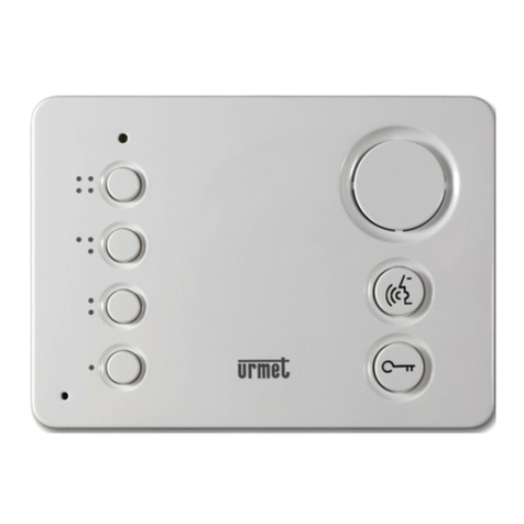
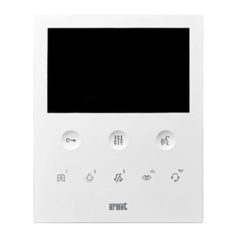
(Vmodo and Miro).
For Vmodo:
1. On the apartment station hold the button pressed for longer
than 5 seconds. The button will blink red slowly to indicate
that programming mode is selected.
2. Select Auto-insertion from the smartphone to the door unit.
Go to step 3b..
For Miro:
1. Establish a call from the door unit to the apartment station.
2. On your smartphone, answer the call and leave the
conversation open.
3. On the apartment station.
a. hold the button pressed for longer than 5 seconds; the
yellow LED will blink slowly to indicate that programming
mode is selected;
b. Then press the button to be programmed (e.g. /
for Mod. Vmodo, / for Mod. Miro) for at least three
seconds until the confirmation tone is heard.
4. On the smartphone, open the pedestrian door.
5. On the apartment station:
a. you will hear a confirmation beep
b. to quit the programming mode, hold the button down for
more than 5 seconds
6. Close the conversation or auto-insertion in progress on the
smartphone.
7. To check the programmed function:
For hands-free models:
a. press the button first and then press the programmed
button (e.g. ).
For models with handset:
a. pick up the handset from the apartment station and press
the programmed button (e.g. or );
b. check presence of the call on your smartphone and the
audio when answering.
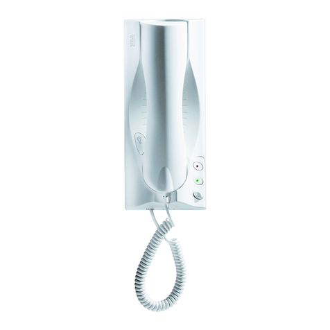
B) Programming with handset off-hook
(Mod. Signo).
1. Make a call from the door station to the apartment station.
2. On your smartphone, answer the call and leave the
conversation open.
3. On the apartment station.
a. Hold the door opener button 1, pressed and lift the
handset 2. A tone coming from the apartment station
will indicate that programming is in progress.
BEE
2
1
b. now press the button 3; to be programmed and wait for
a confirmation tone from the apartment station.
BEE
3
4. On your smartphone, open the pedestrian access door.
5. On the apartment station
a. a beep sound will confirm that programming has been
successfully completed;
b. now hook up the handset of the apartment station - which
will beep to confirm programming mode quitting.
6. On your smartphone, end the current conversation.
7. To check the programmed function:
a. lift the handset off the hook at the apartment station and
press the programmed button;
b. check for the presence of the call on your smartphone and
of a voice feedback when you answer.
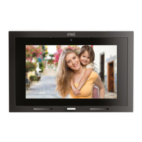
For intercom call programming in the following video door
phone models:
mod. Aiko ref. 1716/1 and 1716/2
mod. Modo ref. 1717/12 and 1717/12H
mod. Folio ref. 1706/5 and 1706/6
please refer to the chapter “(Audio/Video) Settings \ Video
door phone directory \ Adding a record to the directory”
contained in the instruction manual supplied with the
product.
TECHNICAL SPECIFICATIONS
Power supply voltage from BUS line: ..................................... 48 V
External power supply voltage: .............................................. 24 V
Maximum absorption: ............................................................ 200 mA
Absorbed power in operation:............................................... max 6 W
Operating temperature: ..................................................... -5 ÷ +45 °C
Max humidity:..........................................................................95% RH
Interfaccia Ethernet: ....................................................... 10/100 Mbps
WiFi:..................................2,4 GHz (conforms to IEEE 802.11 b/g/n)
with internal antenna
Dimensions (LxHxD): ................ 140 (~8 DIN modules) x 90 x 60 mm
5.51 x 3.54 x 2.36“
The product is designed to be powered either from a BUS
line or external power supply Ref. 1083/24, via 24V (6 W,
24 V ) terminals, with power supply up to the specified
power source requirements (LPS) and protected against
short circuits and overcurrents according to EN 60950 1:
2006 + A11 + A1 + A12 + A2 provisions.
Wires with cross-section area of 0.5 mm2 or larger must
comply with IEC 60332-1-2; wires with cross section area
smaller than 0.5 mm2must comply with IEC 60332-2-2.
KEY TO SYMBOLS
Symbol Description
Direct input voltage .
Video door phone system trademark.
DANGER - Presence of safety-critical components.
See the installation manual of the device.
