2 947830
CAUTION: To reduce the risk of electric shock,
Do not remove cover.
No user serviceable parts inside.
Refer servicing to qualified service personnel.
CAUTION
RISK OF ELECTRIC SHOCK
DO NOT OPEN
This symbol indicates that dangerous
voltage constituting a risk ofelectric
shock is present within this unit.
This symbol indicatesthatthere are
important operating and maintenance
instructions in the literature accompanying
this unit.
Precautionary Designations
FCC Information
This equipment has been tested and found to
comply with the limits for a Class A digital
device, pursuant to Part 15 of the FCC Rules.
These limits are designed to provide
reasonable protection against harmful
interference when the equipment is operated
in a commercial environment. This
equipment generates, uses and can radiate
radio frequency energy and if not installed
and used in accordance with the instruction
manual, may cause harmful interference to
radio communications. Operation of this
equipment in a residential area may cause
harmful interference in which case the user
will be required to correct the interference at
his own expense.
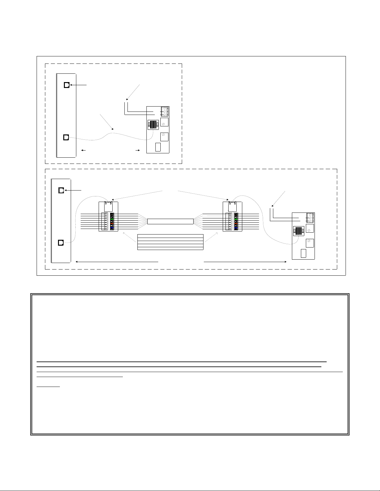
INSTALLATION
Operation:
The VIP-9890AL-CB provides talkback access
via network connection to customer telephone
system or stand alone telephone set. Interface to
customer telephone system can be via SIP
registration to a Voice over IP (VoIP) telephone
system, FXO port (when used with a Valcom
FXS Network Station Port), or FXS port (when
used with a Valcom FXO Network Trunk Port).
Pressing the call button on the speaker assembly
initiates a call to a user-specified telephone
number, and the call assurance LED behind the
intercom unit face plate begins to flash. When
the call is answered, a hands-free
communications path is established to the
speaker, and the call assurance LED behind the
face plate remains lit. The form C relay included
with the VIP-9890AL-CB may be activated by
pressing the # key on the answering telephone,
with the relay typically being used to activate door
entry equipment.
Mounting
For enhanced protection against static
electrical discharge, it is recommended
the intercom unit shipped with the
VIP-9890AL-CB be installed onto a grounded
electrical box, If surface mounted, ground box
to local ground.
The VIP-9890AL-CB speaker enclosure is
designed for double gang FD electrical box
mounting and must be within 350 feet of the
VIP-9890AL-CB Network Interface.
The VIP-9890AL-CB Network Interface is
designed for wall mounting and must be within
100 meters of the network switch. Using the
screws provided, attach the mounting brackets to
the Network Interface, then secure the Network
Interface to the wall. Remove the speaker
assembly from the packing container. Using a
Phillips screwdriver, remove the two screws
securing the front grille to the enclosure. Pre-
drilled 13/64” mounting holes in the back of the
enclosure are designed to fit a single gang,
double gang or octagon outlet box. If not
attaching to an outlet box, use the enclosure as a
template. Hold the enclosure in the desired
position on the wall and mark the location of
mounting holes. Depending on wall construction
type, prepare the mounting hole locations on the
wall to securely attach the enclosure.
Wiring may be inserted through the large hole in
the back of the enclosure, or through the
knockout hole in the top of the enclosure. Insert
wiring for signal connections and relay
connections (if used) through desired hole. Use
mounting hardware (not included) appropriate for
the wall type to securely mount the enclosure to
the wall.
After making signal connections, align the
grille/speaker assembly with the enclosure.
Install the four supplied tamper-resistant screws
through the grille into the enclosure. Use a 1/8”
security hex bit to tighten the screws securely.
Power Connections
The only method of powering a VIP-9890AL-CB
Network Interface is via a Power over Ethernet
(PoE) switch or power injector meeting the
802.3af specification.
Make all required signal connections before
connecting to Ethernet switch or power injector
meeting the 802.3af specification.