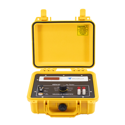
Valhalla Scientific 4314Ki User manual

© 2021 Valhalla Scientific.. All Rights Reserved.
Operation Manual
Wide-Range Digital Igniter Tester
Rev 67.1
4314Ki


1
VALHALLA SCIENTIFIC INC. CERTIFICATION
Valhalla Scientific, Inc. certifies that this instrument was thoroughly tested and inspected and found
to meet published specifications when shipped from the factory. Valhalla Scientific, Inc. further
certifies that its calibration measurements are traceable to the Nation Institute of Standards and
Technology to the extent allowed by NIST’s calibration facility.
Due to continuing product refinement and due to possible parts manufacturer changes, Valhalla
Scientific, Inc. reserve the rights to change any or all specifications without notice.
VALHALLA SCIENTIFIC INC. WARRANTY STATEMENT
The warranty period for this instrument is stated on your invoice and packing list. Please refer to these
to determine appropriate warranty dates.
We will repair the instrument during the warranty period provided it is returned to Valhalla Scientific,
Inc. freight prepaid. No other warranty is expressed or implied.
Valhalla Scientific, Inc. is not liable for consequential damages.
Permission and a Return Material Authorization number (RMA) must be obtained directly from the
factory for warranty repairs. No liability will be accepted if returned without such permission.
Due to continuing product refinement and due to possible parts manufacturer change, Valhalla
Scientific reserves the right to change any or all specifications without notice.
SUPPORT
For repair and calibration services, call 800-548-9806 or visit valhallascientific.com.
Email support available at [email protected]
4314Ki Programmable Digital Igniter Tester User Manual
Revision 67-1 (2022)
Copyright © 2022 Valhalla Scientific, Inc. All rights reserved

2
WARNINGS
The following general safety precautions must be observed during all phases of operation, service, and
repair of this product. Failure to comply with these precautions or with specific warnings elsewhere in this
manual violates safety standards of design, manufacture, and intended use of the product. Valhalla
Scientific assumes no liability for the customer’s failure to comply with these requirements.
Ground the equipment: For Safety class 1 equipment (equipment having a protective earth terminal), an
interrupted safety earth ground must be provided from the main power source to the product input wiring
terminals or supplied power cable.
DO NOT operate the product in an explosive atmosphere or in presence of flammable gases or fumes.
For continued protection, replace the line fuse(s) only with fuse(s) of the same voltage and current rating
and type. DO NOT use repaired fuses or short-circuited fuse holders.
Keep away from live circuits: Operating personnel must not remove equipment covers or shields.
Procedures involving the removal of covers or shields are for the use of service-trained personnel only.
Under certain conditions, dangerous voltage may exist even with the equipment switched off. To avoid
dangerous electrical shock, DO NOT perform procedures involving cover or shield removal unless you are
qualified to do so.
DO NOT operate damaged equipment: Whenever it is possible that the safety protection features built
into this product have been impaired, either through physical damage, excessive moisture, or any other
reason, REMOVE POWER and do not use the product until safe operation can be verified by service-trained
personnel. If necessary, return the product to Valhalla Scientific for service and repair to ensure that safety
features are maintained.
DO NOT service or adjust alone: Do not attempt internal service or adjustment unless another person,
capable of rendering first aid and resuscitation, is present.
DO NOT substitute parts or modify equipment: Because of the danger of introducing additional hazards,
do not install substitute parts or perform any unauthorized modification to the product. Return the
product to Valhalla Scientific for service and repair to ensure that safety features are maintained.
Measuring high voltage is always hazardous: ALL multimeters input terminals (both front and rear) must
be considered hazardous whenever inputs greater than 42V (dc or peak) are connected to ANY input
terminal.
Permanent wiring of hazardous voltage or sources capable of delivering greater than 150VA should be
labeled, fused, or in some other way protected against accidental bridging or equipment failure.
DO NOT leave measurement terminals energized when not in use.

3
Table of Contents
Table of Contents ......................................................................................................................................... 3
1. General Information ............................................................................................................................ 6
Instrument Description ............................................................................................................................ 6
Instrument Identification ......................................................................................................................... 6
Safety Precautions ................................................................................................................................... 6
2. Unpacking and Installing ...................................................................................................................... 7
Inspection ................................................................................................................................................ 7
Power Requirements ............................................................................................................................... 7
Installation ............................................................................................................................................... 7
3. Specifications ....................................................................................................................................... 8
Range/Resolution/Test Current/Failsafe Current .................................................................................... 8
Accuracy ................................................................................................................................................... 8
Temperature ............................................................................................................................................ 9
General Specifications ............................................................................................................................. 9
Physical Specifications ............................................................................................................................. 9
4. Features and Operations ................................................................................................................... 10
Introduction ........................................................................................................................................... 10
Front Panel ............................................................................................................................................. 10
Power Switch ..................................................................................................................................... 10
Display ................................................................................................................................................ 11
Range Selection Keys ......................................................................................................................... 12
Source and Sense Post ....................................................................................................................... 12
Rear Panel .............................................................................................................................................. 13
Fuse Holder ........................................................................................................................................ 13
Charger/Power Receptacle ................................................................................................................ 13
RS-232 Connector .............................................................................................................................. 13
Power Mode Switch ........................................................................................................................... 13
Power Up ............................................................................................................................................... 14
Dual Power Mode .................................................................................................................................. 14
Connecting a Load to the 4314Ki ........................................................................................................... 16
4-Wire Resistance Measurement ...................................................................................................... 16
Interpreting the Display ......................................................................................................................... 18

4
Fail-Safe Operation ................................................................................................................................ 18
Low Battery Indicator ............................................................................................................................ 19
5. Optional Features and Accessories .................................................................................................... 20
Options .................................................................................................................................................. 20
Accessories ............................................................................................................................................ 20
A2: Battery Charger ........................................................................................................................... 20
Replacement Batteries ....................................................................................................................... 20
Test Leads .............................................................................................................................................. 20
Alligator Clip Type Leads .................................................................................................................... 20
Needle Type Probes ........................................................................................................................... 21
Surface Probes ................................................................................................................................... 21
Other Lead Sets .................................................................................................................................. 21
6. Remote Operations ............................................................................................................................ 22
Safety Isolated RS-232 Interface ............................................................................................................ 22
Connecting the 4314Ki via RS232 ...................................................................................................... 22
COMMANDS AND SYNTAX ................................................................................................................. 23
DETAILS OF COMMAND REFERENCE .................................................................................................. 23
7. Routine Maintenance ........................................................................................................................ 28
General .................................................................................................................................................. 28
Required Test Equipment ...................................................................................................................... 28
Precision Resistors: ............................................................................................................................ 28
Test Leads: ......................................................................................................................................... 28
Voltage Standard: .............................................................................................................................. 28
DMM: ................................................................................................................................................. 28
Power Supply: .................................................................................................................................... 28
Calibration Procedure ............................................................................................................................ 29
VOLTAGE SENSE ADJUSTMENTS ........................................................................................................ 29
SOURCE ADJUSTMENTS ..................................................................................................................... 31
FAILSAFE CHECK ................................................................................................................................. 31
Checking the Calibration Results ........................................................................................................... 32

½ Scale and Linearity Check ............................................................................................................... 32
Zero Check ......................................................................................................................................... 32
Battery Replacement Instructions ......................................................................................................... 32


5
8. Addendum ......................................................................................................................................... 33

6
1. General Information
Instrument Description
Welcome to a new era of Protection. Featuring the intrinsically safe internal circuitry of our storied 4314
Igniter Tester line, the 4314Ki begins the next generation of precision measurement instruments.
Covering a wide 8-measurement range, the 4314Ki is an ideal fit for the aerospace, defense, renewable
energy, and manufacturing industries. This unit can easily replace multiple other instruments while
providing clearer, more useful data. Some applications include squib circuits, fuses, release mechanisms,
thrust vector motor control, deployment systems, pyrotechnic initiators, primers, and generic circuity
continuity testing.
As in the past, safety and reliability have been the fundamental focus throughout the conception,
prototyping, and testing process. Externally, the unit is housed in a durable, impact-resistant aluminum
case built for both laboratory and field use. Internally, the 4314Ki incorporates our redundant fail-safe,
current-limiting network circuitry ensuring the instrument test currents cannot exceed the specified
amount, even in the unlikely event of a worst-case component failure.
Additionally, the 4314Ki introduces Dual Power Mode and an Isolated Serial Interface. Dual Power Mode
offers the operator either 18 hours of battery life or a 24/7 continuous power mode with the ability to
change via a key switch on the rear of the unit. The isolated serial interface allows for remote control of
the unit through an RS-232 port on the back panel. Digital signals are transmitted across the isolation
barrier using iCoupler technology. Via the interface, the user can fully operate the meter and query
measurement and configuration data.
Please read this manual thoroughly and all accompanying addendums before attempting to operate this
ohmmeter.
Instrument Identification
Valhalla Scientific instruments are identified by a two-part serial number. The Serial Tag is located on the
rear or bottom of the instrument. The number is in a form of 67-0000. The first two digits, called the serial
number prefix, indicate the model. It changes only when a change is made to the instrument. The last 4
digits, called the serial number suffix, are unique for each individual unit.
Be sure to include the entire serial number, both prefix and suffix, in any correspondence about your
instrument.
Safety Precautions
For an increased level of safety, plug the 4314Ki to a power source only while charging the batteries or
in Continuous Power Mode.
Do not switch between power modes while the device is powered on.

7
2. Unpacking and Installing
Inspection
If the shipping carton is damaged, request that the carrier's agent be present when the unit is unpacked.
If the instrument appears damaged, the carrier's agent should authorize repairs before the unit is returned
to the factory. Even if the instrument appears undamaged, it may have suffered internal damage in transit
that may not be evident until the unit is operated or tested to verify conformance with its specifications.
If the unit fails to operate or fails to meet the performance specifications, notify the carrier's agent and
the nearest Valhalla Sales Office. Retain the shipping carton for the carrier's inspection. DO NOT return
equipment to Valhalla Scientific, Inc., or any of its sales offices prior to obtaining authorization to do so.
Power Requirements
The Model 4314Ki is powered by four internal rechargeable heavy-duty Nickel–metal hydride (NiMH)
batteries. The batteries are charged by an external AC/DC converter that plugs into a standard receptacle.
The AC adapter can accept an input voltage from 100 to 240 Vac (50-60Hz) and an output of 9VDC @
305mA.
The 4314Ki can also support supplies from 6V to 9Vdc @ 300mA to 1.25A.
The unit is equipped with a 2A Fast Blow fuse installed on the rear panel.
To charge the batteries, the device must be:
1. In Battery Mode
2. Turned Off
3. Connected to the power Supply/Charger.
The battery pack may power the 4314Ki for up to 18 hours before requiring a recharge.
Although the batteries are fully charged prior to shipment, it may be desirable to refresh the charge for
24 hours before use. It takes approximately 16 hours to fully charge the batteries.
In Continuous Power Mode, the 4314Ki will function uninterrupted while connected to the power supply.
While in this mode, the batteries are not under charge, even is the device is turned off.
Installation
The Model 4314Ki consumes little power and generates virtually no heat. Consequently, it may be used
in any area where the environment does not exceed the temperature specifications of Chapter 3.

8
3. Specifications
This section contains accuracy and operational specifications for the Model 4314Ki. The accuracy
specifications are valid for a period of one year from the date of calibration at a temperature of 15°C
(59°F) to 35°C (95°F). Outside this range, the temperature coefficient specification applies.
Range/Resolution/Test Current/Failsafe Current
Table 1
Range
Value
2Ω
20Ω
200Ω
2kΩ
20kΩ
200kΩ
2MΩ
2MΩ
Standby
Resolution
100μΩ
1mΩ
10mΩ
100mΩ
1Ω
10Ω
100Ω
1kΩ
-
Test
Current
5mA
5mA
500µA
50μA
5μA
500nA
50nA
5nA
0A
Fail-Safe
Current[1]
8mA
8mA
1.8mA
180μA
18μA
1.8μA
180nA
18nA
-
[1] Maximum value. Actual Failsafe Currents vary from instrument to instrument. The actual measured
level is provided on the certificate of calibration.
Accuracy
Table 2
Range
Accuracy
2Ω
±0.03% of reading ± 0.02% of range
20Ω
±0.03% of reading ± 0.02% of range
200Ω
±0.03% of reading ± 0.02% of range
2kΩ
±0.03% of reading ± 0.02% of range
20kΩ
±0.03% of reading ± 0.02% of range
200kΩ
±0.05% of reading ± 0.05% of range
2MΩ
±1% of reading ± 0.2% of range
20MΩ
±2% of reading ± 0.2% of range

9
Temperature
Temperature Coefficient: ±0.002% per °C (from 0°C-15°C and 35°C-50°C)
not applicable for 200kΩ range and above.
Operating Temperature Range: 0°C to 50°C
Storage Temperature Range: -10°C to 70°C
General Specifications
Display Type: 4 ½ digits OLED (19999)
Overload Indication: Screen displays “O.L.”
Conversion Rate: 3 readings per second
Terminal Configuration: 4-Wire Kelvin
Current Source Compliance Voltage: Clamped at 1.6V
Power: (4 “D” Cell) 1.2V rechargeable NiMH Batteries 10000mAh
Battery Charger: Provides 9VDC at 300mA nominal
Physical Specifications
Width: 9.75” / 24.8cm
Depth: 11.5” / 29.2cm
Height: 3.5” / 8.9cm
Weight: 6.2lbs / 2.8kg net

10
4. Features and Operations
Introduction
This chapter covers the fundamentals of Igniter Tester operation. It shows how to use the 4314Ki front
and rear panels, how to make connections, and describes the display sections and messages. Before using
the instrument to make measurements, it is important to familiarize yourself with each section of the
front and rear panel of the 4314Ki.
Front Panel
The front panel of the 4314Ki can be broken down into 4 parts. In Figure 1 you can see the regions
indicated by their name.
Figure 1 - 4314Ki Front Panel Callouts
Power Switch
Battery Mode: When the front panel power switch is placed in the OFF/CHARGE position, all power is
removed from the output terminals, and the battery pack is connected to the charging circuit. When the
switch is placed in the ON position, the battery pack is disconnected from the charging circuit. The
possibility of a common mode voltage between the device under test and AC Power ground is therefore
eliminated. The switch also functions as a low battery indicator. When battery level is within operational
limits, the switch will illuminate in blue. Once the battery voltage level drops below the minimum
operational limit, the switch will change to red.
Continuous Power Mode: The switch is simple used to turn the 4314Ki on and off.

11
Display
During measurements, the display presents 4 sections.
Measurement
Under normal operations, the Ohms display will indicate the value of the resistance being measured. The
multiplier will indicate whether the value displayed is in Ohms, kOhms or MOhms. (ohms, kilo-ohms or
mega-ohms).
Battery and Power Mode Indicator
Indicates that the device is in battery mode.
Device has approximately 18-12 hours of charge left before low battery.
Indicates that the device is in battery mode.
Device has approximately 12-6 hours of charge left before low battery.
Indicates that the device is in battery mode.
Device has approximately 6-1 hours of charge left before low battery.
Indicates that the device is in battery mode.
Battery is low and that readings should not be trusted. An overnight recharge should be
performed before using the 4314Ki.
Indicates that the device is in Continuous Power Mode.

12
Range and Test Current
Indicates the range selected and the test current level used.
Local/Remote Indicator
This section of the display indicates the remote/local state of the instrument. If RMT is displayed, the
instrument is in remote state and can only receive commands through its remote interface port. If the
section is blank, the 4314Ki is in local state and will receive commands from the front panel keys.
Range Selection Keys
The eight range keys allow the user to select the required measurement range of the instrument. Each
key is labeled with the respective range value.
Source and Sense Post
Connections to the 4314Ki are made via the front panel source/sense terminals, which consist of two red
and two black standard binding posts. The posts can accept standard banana plugs, wires up to 12 AWG,
or spade lugs. The four terminals provide full 4-Wire Kelvin measurement capability. The right posts are
the positive and negative current source terminals and provide the test current, while the left posts are
the positive and negative voltage sense terminals used to monitor the voltage drop across the load.
The 4-Wire configuration eliminates errors normally caused by test lead and contact resistances. In many
applications, the contact resistance can exceed the value of the load by several orders of magnitude. The
4314Ki bypasses this potential error source by providing two terminals of constant current and an
additional two terminals for high impedance voltage sensing. The result is a fast, accurate resistance
measurement of the load, independent of the resistance of the current carrying leads. Later in this chapter
we will illustrate how the 4-wire principle is used to eliminate lead, wire, and contact resistances as
potential error sources.

13
Rear Panel
The rear panel of the 4314Ki may vary from unit to unit based on the features installed. If the 4314Ki that
you are using features terminals or connectors that are not described in this section, please refer to any
available addendum that references the particularities of your model.
Fuse Holder
The fuse holder is mounted on the rear panel and contains a 2 amp in-line fuse. This fuse is designed to
protect the battery pack from excessive charging currents. For continued protection, replace the line fuse
only with fuse of the same voltage and current rating and type. DO NOT use repaired fuses or short-
circuited fuse holders.
Charger/Power Receptacle
The battery charging jack is a barrel type and is located on the 4314Ki rear panel. The center pin of the
connector is positive. The charging requirements of the internal battery pack are 9VDC @ 300mA. The
device can however accept 6 to 9Vdc @ 300mA to 1.25A. The correct charging voltage is supplied by the
adapter included with the instrument. Additional adapters are available as Option "A2". The charger is
equipped with a locking ring and is sealed IP68.
RS-232 Connector
The RS-232 interface of the 4314Ki is an ultra-safe isolated serial Interface. The digital signals are
transmitted across the isolation barrier using iCoupler technology. The RS-232 serial interfacing is done
through the 9-pin female D-Sub connector located on the rear panel of the instrument. Knowledge of the
specific pin functions of the serial connector may be necessary for certain applications; see chapter 6
(Remote Interface) for connector pin assignment.
Power Mode Switch
Power Mode Selection Key Switch allows the use to select Battey or Continuous Power Mode.

14
Power Up
Before applying power, please refer to chapter 2.
Turn on the 4314Ki by pressing the front panel power switch into the ON position. The switch will
illuminate blue (or Red if the batteries are low). If the device does not to turn on, check the line power
fuse. If the fuse is intact, switch the device off and charge the batteries for 16 hours.
Once you have turned on the 4314Ki, it will start its power-on routine. On the display you should see the
following messages:
In this state, the device does not output test current. To continue, the user can manually select a range
from the front panel keypad or send a range command via the serial interface.
It is important to note that in the power up (or Standby) state, the 4314Ki will only respond to a keypress,
a range select command, or an identification query.
Dual Power Mode
The 4314Ki introduces Dual Power Mode offering the operator
either 18 hours of battery life or a 24/7 continuous power mode.
The user can change power mode via a key switch on the rear of
the unit (described in the previous section). The key switch acts as
an additional safety feature, preventing non-authorized users
from changing modes.
The key can only be inserted or removed while in Battery Mode
position. This prevents unauthorized selecting of Continuous
Power.
To place the 4314Ki in Continuous Power Mode, turn the key clockwise to a horizontal position. In this
position, the key cannot be removed.
To return the device back to Battery Mode, turn the key counterwise to a vertical postion. In this position,
the key can be removed to perminatly lock the 4314Ki in Battery Mode.
WARNING! – ALWAYS TURN THE 4314Ki OFF BEFORE CHANGING POWER MODES.

15
The user can easily detect the mode selected by looking at the symbol in the top right corner of the display.
Indicates that the device is in Battery Mode
Indicates that the device is in Continuous Power Mode.
When in Battery Mode, the 4314Ki run of 4 NiMH D Cell batteries. The batteries are charged only while
the device is in battery mode and turned off. Internal safety line isolation switch disables the battery
charging circuit when the 4314Ki is ON. All power is removed from the source circuitry when the unit is
OFF and in charging mode.
In Continuous Power Mode, the 4314Ki is powered via the provided power supply (also used as a battery
charger). This configuration is a safe option for applications that require longer testing times.

16
Connecting a Load to the 4314Ki
Connections are made to the front panel terminals using a 4-wire
configuration as described in 4-Wire Resistance Measurement. When
using Valhalla test leads, the tabbed side of the banana jack is plugged
into the current terminals. This ensures that the current is carried in the
largest conductor and that the voltage input is shielded.
VHI ☼ ☼ IHI ←Tab
VLO ☼ ☼ ILO ←Tab
4-Wire Resistance Measurement
The four-terminal configuration of the 4314Ki eliminates errors normally caused by test lead and contact
resistances. In many applications, the contact resistance can exceed the value of the load by several orders
of magnitude. The 4314Ki bypasses this potential error source by providing two terminals of constant
current and an additional two terminals for high impedance voltage measurement. The result is a fast,
accurate resistance measurement of the load, independent of the resistance of the current carrying leads.
Figure 2 - Error Sources in Resistance Measurements
Figure 2 illustrates how the 4-wire principle is used to eliminate lead, wire, and contact resistances as
potential error sources. The internal current source inherently overcomes all series resistance (within
compliance voltage limits) and delivers a precise constant current.
The internal high-impedance DVM senses the voltage drop across the load. There is negligible contact and
lead resistance error created by the voltage measurement because the high input impedance of the DVM
limits current flow in the voltage leads.

17
The most common termination is alligator type clips. If this is your choice of leads, simply connect one clip
to one end of your load and the other clip to the opposite side of the load.
For flat surfaces, you can choose between two different spring-
loaded surface probes. If this is your choice of leads, simply press
one probe against one side of the surface of your load, making
sure that the surface of the probe is in full contact with the
surface of the load. Press the second probe against the surface
at the oppose side of your load making sure that the surface of
the probe is in full contact with the surface of the load.
For hard-to-reach surfaces, Valhalla Scientific offers two
different sets of spring-loaded dual needle probes that
differentiate in overall size and distance between the needles. If
this is your choice of leads, simply press both the needles of one
probe against one end of the surface of your load, press both
needles of the second probe against the surface at the oppose
end of your load.
See chapter 5 for a full list of lead sets and accessories for your
4314Ki.

18
Interpreting the Display
All Valhalla ohmmeters and igniter testers use a high impedance voltmeter as part of the resistance
measurement process. This voltmeter is a highly accurate and stable 24 bit analog-to-digital converter
(ADC). Unless it is receiving a definite input signal, the output reading of this ADC is ambiguous. The display
may indicate a randomly wandering number or it may indicate an over-range condition. This unpredictable
display may make it seem to appear that the instrument is experiencing some sort of malfunction. It is, in
fact, just a characteristic of the voltmeter circuit and should not be mistaken for a fault in the instrument.
The display indications should be ignored unless there is a definite measurement being taken. If this
wandering display is not acceptable, the ohmmeter can be made to indicate zero whenever the sense
terminals are shorted.
The display should indicate a stable reading when the test leads are securely attached to the device under
test. If the display appears to be erroneous when connected to a load, recheck the test leads for integrity
and cleanliness. If all external items appear to be functioning properly, the problem may be the
ohmmeter. In this case, please contact your local Valhalla Scientific Sales Office.
Fail-Safe Operation
The 4314Ki incorporate a proprietary current source design that renders them incapable of delivering
excessive voltage or current to the device under test. Maximum Fail-Safe Current values are list in Table
3.
Range
Fail-Safe Current
2Ω
< 8mA
20Ω
< 8mA
200Ω
< 1.8mA
2kΩ
< 180µA
20kΩ
< 18µA
200kΩ
< 1.8µA
2MΩ
< 180nA
20MΩ
< 18nA
Table 3 - Fail-Safe Current Values per Range
Every 4314Ki Igniter Testers are thoroughly tested before the leaves the factory. This includes a failsafe
test that simulates a "worst case" failure condition. The resulting output current is recorded and provided
on the Certificate of Calibration included with every unit.
Table of contents
Other Valhalla Scientific Test Equipment manuals

Valhalla Scientific
Valhalla Scientific 4176 User manual

Valhalla Scientific
Valhalla Scientific Alpha 4314 Series User manual

Valhalla Scientific
Valhalla Scientific 4314KV User manual

Valhalla Scientific
Valhalla Scientific 4314Mi User manual

Valhalla Scientific
Valhalla Scientific Alpha 4314 Series User manual

Valhalla Scientific
Valhalla Scientific 4314KVM User manual

Valhalla Scientific
Valhalla Scientific 2701C Manual