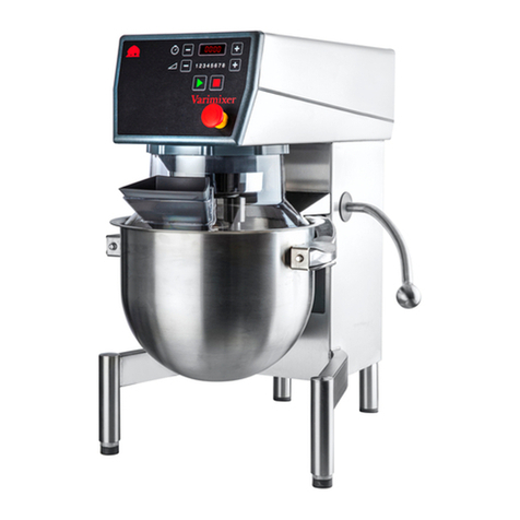
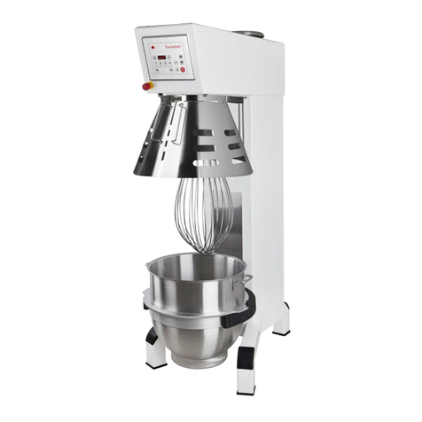
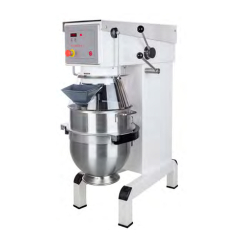
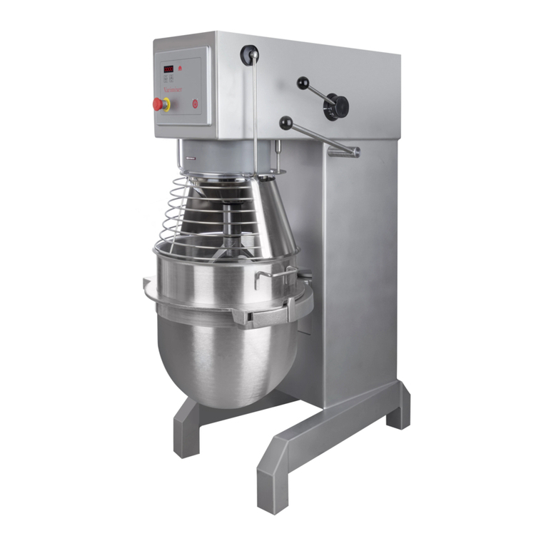
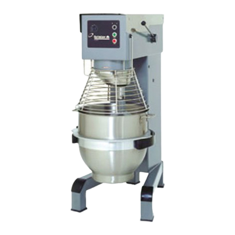
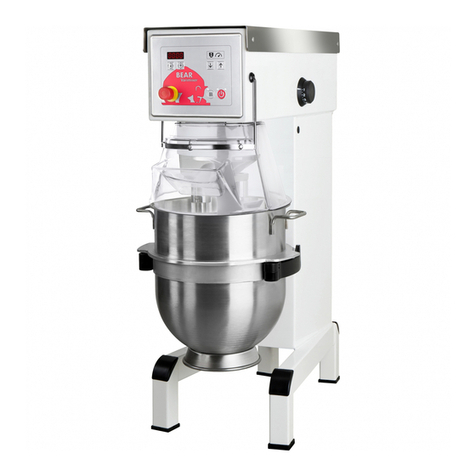
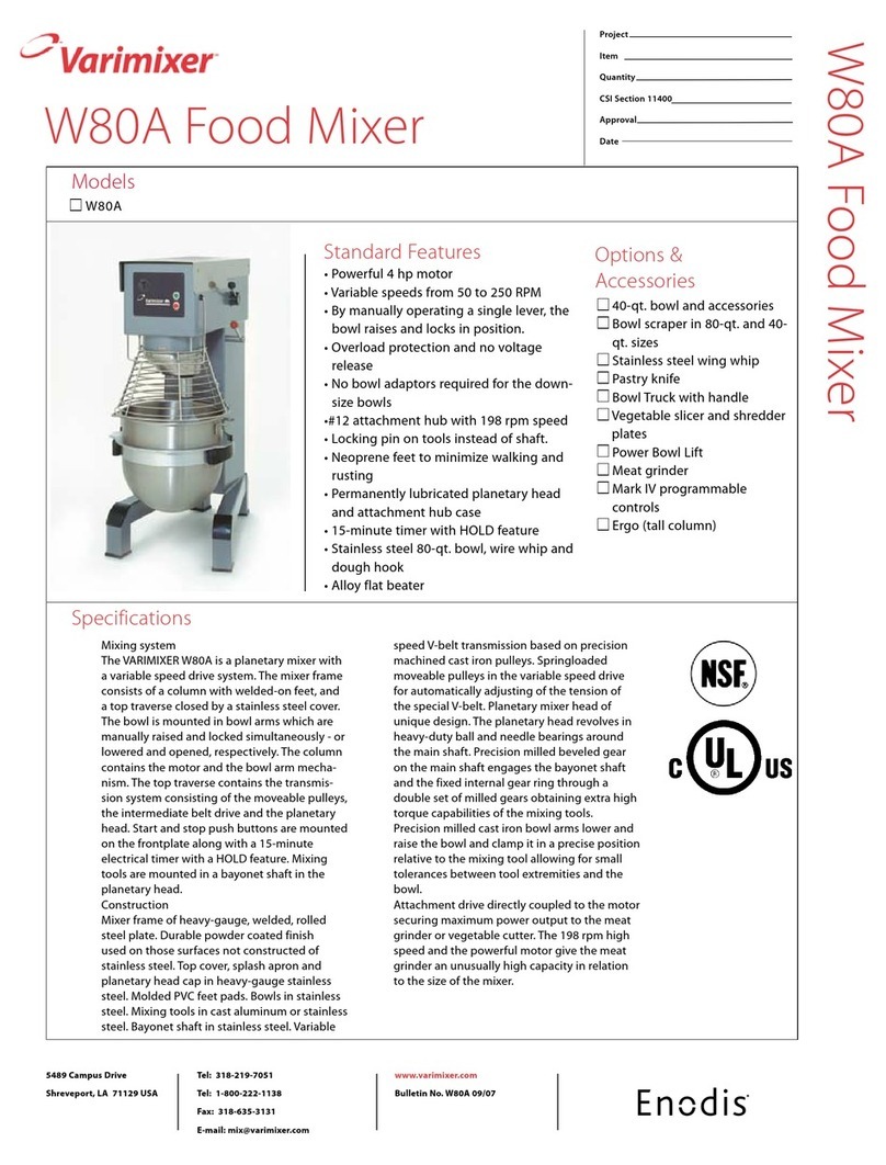
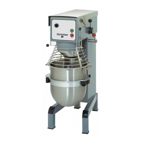
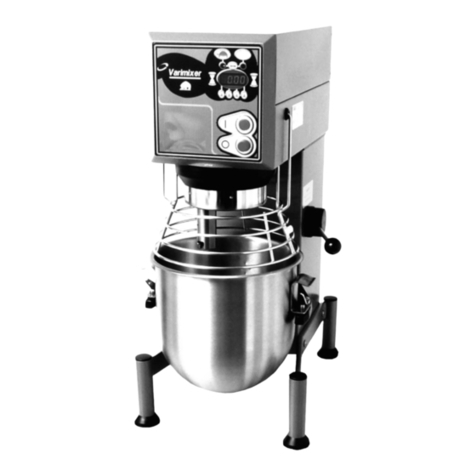
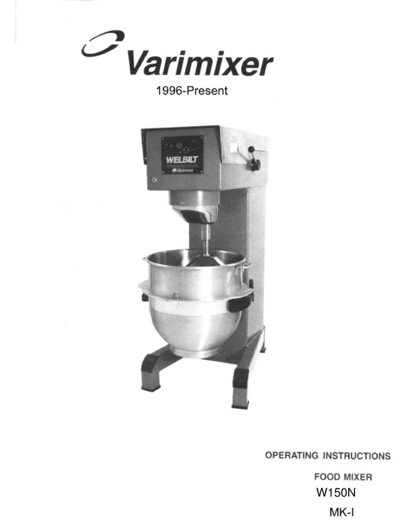
Varimixer V20 User manual

1
SPARE PART AND OPERATION MANUAL
FOOD MIXER
Model V20
012016

2
Caution -READ BEFORE OPERATING- Caution
Varimixer recommends that mixer operators be at least 18 years of age and be thoroughly trained on
the use, cleaning and lubrication of the mixer.
This manual should be seen as an integral part of the mixer and should be kept by the machine
throughout its working life.
Before the machine is commissioned, it is important to read these instructions thoroughly.
The manufacturer may update the product manual without updating this copy of the manual
Varimixer recommends that the following precautions be adopted to help make the mixer operation
safer and more efficient.
........- All operators should be at least 18 years of age.
- All operators should be thoroughly trained before being allowed to operate the mixer.
- NEVER reach into the bowl when the mixer is running.
- Do not wear loose clothing or rings while operating the mixer.
- Stop the mixer and lower the bowl before adding ingredients, scraping the bowl, removing the
............agitator, or removing the product.
- Stop the mixer before removing or installing attachments into the drive hub.
- Do not attempt to assemble or disassemble attachments while mounted into the drive hub.
- Always use the pusher plate with the slicer/meat grinder attachments.
- NEVER bypass the safety mechanisms supplied on the mixer. Doing so can cause injury and
............is the responsibility of the user to insure these safety mechanisms are operating properly.
Unpacking:
The machine should be unpacked and the packaging disposed of according to regulations applicable
in the country concerned.
TransporT:
Lifting equipment should always be used to move the machine. Allowance should be made for the
fact that the machine is ‘top-heavy’.
The machine must not be pulled or lifted by the bowl lift handle.
When the machine is moved, it should be in a vertical position at all times.

3
Varimixer warrants its commercial mixers to the original purchaser against defects in material or manufacture for a period of one
year from the date of original purchase, subject to the following exclusions and limitations. The warranties provided by Varimixer
do not apply in the following instances:
1. In the event that the equipment is improperly installed. Proper installation is the responsibility of the installer, proper installation
procedures are covered in the Varimixer Spare Parts and Operations Manual.
2. In the event that the equipment is improperly maintained. Proper maintenance is the responsibility of the user. Proper mainte-
nance procedures are covered in the Varimixer Spare Parts and Operations Manual.
3. In the event that failure or malfunction of the appliance or any part thereof is caused by abnormal use or is otherwise not attribut-
able to a defect in material or manufacture.
4. In the event that the appliance , by whatever cause, has been materially altered from the condition in which it left the factory.
5. In the event that the rating plate has been altered or removed.
6. On parts which would normally be worn or replaced under normal conditions.
7. With regard to adjustments and/or calibrations. Checking of and changes in adjustments and calibrations are the responsibility of
the installer, Proper installation is the responsibility of the installer, proper installation procedures are covered in the Varimixer
Spare Parts and Operations Manual.
If any oral statements have been made regarding the appliance, such statements do not constitute warranties and are not part of the
contract of sale. This Limited Warranty constitutes the complete, final and exclusive statement with regard to warranties.
LIMITED WARRANTY
EXCLUSIONS
In the event of warranty claim or otherwise, the sole obligation of Varimixer shall be the repair and/or replacement at the option of
Varimixer, of the appliance or component or part thereof Such repair or replacement shall be the expense of Varimixer except that
travel over 100 miles or two hours, overtime, and holiday charges shall be,, the expense of the purchaser. Any repair or replacement
under this warranty does not constitute an extension of the origin, warranty for any period for the appliance or for any component
part thereof. Parts to be replaced under this warranty will be repaired or replaced at the option of Varimixer with new or functionally
operative parts. The liability of Varimixer on any claim of any kind, including claims based on warranty, expressed or implied, con-
tract, negligence, strict liability or any other theories shall be solely and exclusively the repair or replacement of the product as stated
herein, an such liability shall not include, and purchaser specifically renounces any rights to recover, special, incidental, consequen-
tial or other damages of any kind whatsoever, including, but not limited to, injuries to persons or damage to property, loss of profits
or anticipated profits, or loss of use of the product.
LIMITATIONS OF LIABILITY
TO SECURE WARRANTY SERVICE
If you claim a defect covered by this Limited Warranty, first direct your claim to the local Authorized Service Agency, giving model,
serial and code numbers, voltage, a description of the problem and your sales slip. If this procedure fails to be satisfactory to you,
you may write to the Varimixer National Service Manager, 14240 South Lakes Drive, Charlotte, NC 28273; you should include the
information listed above.
..
THIS LIMITED WARRANTY IS EXCLUSIVE AND IS IN LIEU OF ALL OTHER WARRANTIES WHETHER..
WRITTEN, ORAL OR IMPLIED, INCLUDING, BUT NOT LIMITED TO, ANY WARRANTY OF..MERCHANTABILITY
OR FITNESS FOR PARTICULAR PURPOSE OR WARRANTY AGAINST LATENT...DEFECTS.

4
Table ofconTenTs
insTallaTion and fixing:
The ambient temperature around the machine must not exceed 113oF.
If the mixer is placed on a table, it must always be bolted into the table top. The bolts xing the mixer on the pallet can be used
for this, no nuts are needed as there are threads in the bottom plate of the mixer (see page 5).
Electrical connection:
For the benet of service staff, it should be clear to see when the mains plug to the mixer has been removed from the socket in
the wall.
Ensure that the voltage, phase and hertz printed on the identication plate of the mixer are the same as that at the place of
installation. The identication plate is located at the top of the right side of the mixer. Be sure the mixer is properly connected
to the incoming power supply and the ground or earth connection is made. The arrow on the front of the planetary head (see
drawing 2, page 1), indicates the direction of rotation of the planetary head. On three-phase motors the direction of rotation can
be changed by interchanging two phases of the connecting cable or the motor. Electrical connections must be made in accord-
ance with local regulations.
commissioning:
Bowl, tools and safety guard should be cleaned before use – see section on Cleaning, page 6.
recommended Use of The machine:
The machine is designed for the manufacture of products that do not trigger any reactions or release substances that may be
harmful to the user when in use.
The machine must not be used in an explosive atmosphere.
The mixer is designed for commercial use in kitchens, catering outlets and bakeries.
The machine may only be used as specied in this manual.
Unless the change is recommended by the manufacturer, modifying the machine is prohibited.
If the machine is tted with an attachment drive, only accessories produced or recommended by Varimixer should be attached.
Unpacking:........................................................................................................................................................ 2
TransporT: ....................................................................................................................................................... 2
insTallaTion and fixing: ................................................................................................................................... 4
commissioning: ................................................................................................................................................. 4
recommended Use of The machine:................................................................................................................... 4
consTrUcTion of The mixer: ............................................................................................................................. 5
Technical daTa: ................................................................................................................................................ 5
The maximUm capaciTy of The mixer: ................................................................................................................. 5
dimension skeTch: ............................................................................................................................................ 5
safeTy: .............................................................................................................................................................6
correcT Use of Tools: ..................................................................................................................................... 6
aTTachmenT hUb: .............................................................................................................................................. 6
recommended max. speeds ............................................................................................................................... 6
operaTing insTrUcTions.................................................................................................................................... 7
overloading:.................................................................................................................................................... 8
cleaning:.......................................................................................................................................................... 8
lUbricaTion and grease Types: ........................................................................................................................ 8
service insTrUcTions ........................................................................................................................................ 9
machine colUmn ............................................................................................................................................ 14
lifTing sysTem ................................................................................................................................................ 16
pUlley sysTem................................................................................................................................................ 18
planeTary head ............................................................................................................................................. 20
aTTachmenT hUb ............................................................................................................................................. 22
elecTrical componenTs ................................................................................................................................. 24
bowl screen ................................................................................................................................................. 26
Tools and aTTachmenTs ................................................................................................................................ 28
elecTrical diagram ....................................................................................................................................... 30

5
Technical daTa:
Gross weight ......................................233 Lbs.
Net weight ..........................................196 Lbs
Level Capacity, large bowl..................21 Qt.
Level Capacity, small bowl.................13 Qt.
Agitator speed, min. ...........................100 R.P.M.
Agitator speed, max. ..........................400 R.P.M.
Attachment hub..................................90-420 R.P.M.
Motor Power.......................................1 HP
Voltage ...............................................115 V
Ampers, full load.................................112A
60 Hz / 1 Phase
dimension skeTch:
The maximUm capaciTy of The mixer:
consTrUcTion of The mixer:
Bowl Lift Arms
Motor
Machine Label
Toothed Belt
Arrow indicating the rotation
direction of the planetary head
Bowl Lift
Attachment Hub
Planetary Head
Bottom Plate
Nut retaining the bottom plate
Bayonet Socket
Screws for xing
on table
V20 17 7/8”
40”
34 7/8”
26 1/2”
Product V20
Dough, Bread 65%AR 25 lbs.
Dough, Bread 50%AR 12 lbs.
Dough, Donut - Yeast 20 lbs.
Dough, Donut - Cake 23 lbs.
Pie Dough 21 lbs.
Cookie, Dough 14 lbs.
Mufns 24 lbs.
Mashed Potatoes 17 lbs.
Pancakes, Wafes 9 qts.
Whipped Cream 4 qts.
Cake, Layer 23 lbs.
Eggs & Sugar 9 ea.
Icing, Fondant 14 lbs.
Egg Whites 1 qts.
Cake, Cup 25 dz.
Cookies, Sugar 40 dz.
%AR = weight of liquids
weight of our
Batch size and/or speed reduction may be necessary due to one of the following conditions:
1. High Gluten Flour
2. AR% under 40%
3. Water Temp. under 65 degrees F.
Water Weights
1 Gallon = 8.33 lbs.
1 Quart = 2.08 lbs.
1 Pint (16 oz.) = 1.04 lbs.
1 Cup = 0.52 lbs.
AV Donut Weight
Yeast Raised = 1 1/2 oz. per dz.
Cake Raised = 1 lb. per dozen

6
safeTy:
The machine is designed for the manufacture of products that do not trigger any reactions or release substances that
may be harmful to the user when in use.
User safety is assured as follows:
• Tools can only rotate when the bowl screen is closed and the bowl is lifted.
• No access to rotating tools.
• Clearance between screen/stand and lifting handle at least 1 31/32".
• Noise level under 70 dB.
The machine is protected against overvoltage.
The machine should be positioned to allow space for normal use and maintenance.
Non-ionising radiation is not produced intentionally, but rather technically conditioned by electrical equipment (e.g. electric mo-
tors,livepowerlines or solenoids).The machine isnotequippedwith strong permanentmagnets.Bymaintaining a safedistance
(between the eld source and implant) of 11 13/16", any impact on active implants (e.g. pacemakers, debrillators) can likely
be prevented.
The following recommendations apply to work with powdery ingredients:
• Powdery ingredients should not be poured into the bowl from a great height.
• Bags of e.g. our should be opened at the bottom, down in the bowl.
• Do not run up to the maximum speed too quickly.
Placing your hands in the bowl while the machine is running may cause physical injury.
correcT Use of Tools:
Recommended uses of tool:
The whip should not be struck against hard objects such as the edge of the bowl. This will shorten the life of the tool
because of increasing deformation.
To make mashed potato, use the beater and then the standard whip.
aTTachmenT hUb:
The machine may be tted with an attachment drive into which optional accessories, such as meat mincers and vegetable
cutters, can be attached.
For further information on the assembly and use of optional accessories, please refer to the manual that comes with the ac-
cessory.
recommended max. speeds
1 2 3 4 5
MIN MAX 1 2 3 4 5
MIN MAX

7
Varimixer
BEAR
0123
4
5
6
7
8
9
10
11
12
13
14
15
HOLD
Varimixer
BEAR
0123
4
5
6
7
8
9
10
11
12
13
14
15
HOLD
Varimixer
BEAR
0123
4
5
6
7
8
9
10
11
12
13
14
15
HOLD
654
7 8
2 3
1
Varimixer
I
0
BEAR
Place the tool in the bowl.
Place the bowl in the bowl arms.
Ensure that the bowl is placed correctly.
Place the mixing tool in the bayonet
shaft. The pin of the tool must be
turned into the bayonet hole.
Raise the bowl to working position by
pulling the handle forward. Ensure that
the bowl is placed correctly while the
bowl is lifted. Close the bowl screen.
Push the speed selector lever to obtain
the required speed.
The speed must be changed
only when the mixer is running.
On the timer set the time required, by
turningthetimertotheright.The mixer
will stop automatically, when the time
runs out. Set the timer on HOLD when
not used; otherwise the mixer will not
start.
Before the mixer is stopped, the speed
selector lever must be moved to the low-
est speed.
The mixer must not be started
when loaded in high speed position.
Stop the mixer by pressing the red
stop button > STOP <
Startthe mixer by pressing the green
start button > START <
The mixer must only be
started when the bowl is in work-
ing position, and bowl screen is
closed.
operaTing insTrUcTions

8
overloading:
The mixer must not be overloaded.
Possible overload situations:
• Working with excessively tough and heavy dough
• Mixer tool exceeding the recommended speed
• Wrong mixer tool being used.
Big lumps of grease or cooled ingredients must be divided into ne particles before being placed into the bowl. A long period of
overloading will cause the thermal overload relay to stop the mixer. Let the mixer rest for approximately three minutes and press
the RED STOP button BEFORE pressing the GREEN START button.
If the mixer is stopped in high speed when loaded, the bowl is to be removed from the mixer and the speed set to low speed
before the bowl is placed in the mixer again.
cleaning:
The machine should be cleaned daily after use. It should be wiped with a soft brush and clean water. Synthetic detergents
should be used with care, as they destroy the lubricants in the machine.
The machine should never be rinsed with a hose.
Aluminium parts should not be used for strongly acidic, alkaline or saline food products, which may attack non-coated
aluminium.
Aluminium mixer tools must not be washed in strongly alkaline agents (pH between 5.0 and 8.0).
Dough Hook Cleaning:
Special care should be given to cleaning the dough hook. The Varimixer dough hook is manufactured of stainless steel and we
recommendthatit be cleanedandsanitized in acommercialdish machine.Analternate cleaning procedureisto vigorously scrub
the dough hook with a hot water and detergent solution. Use a heavy bristled brush. After cleaning, sanitize the dough hook by
rinsing with a 50 ppm solution of sodium hypochlorite.
The soap suppliers may be able to help by recommending the right type of soap.
The machine must be shut down when the accessory is tted to the attachment drive.
lUbricaTion and grease Types:
When the mixer is used regularly, the varispeed system must be lubricated approximately once each month. When the mixer is
extensively used, or used often without changes in speed, lubrication intervals should be shorter.
Directions for Lubrication:
Start the mixer and increase the speed to approximately 50%. Stop the mixer and remove the top cover by removing
the two screws (2).
The lid of the mixer may only be removed when the cable to the mains supply has been removed.
A grease nipple is located at the top of each of the pulley sets. Press the grease through the grease nipples until the
grease gun feels hard, or until grease is pressed out between the shaft
and the pulleys.
Replace the top cover and remember to replace the two screws secur-
ing the cover.
The lid must be mounted before starting the mixer.
Start the mixer and set the speed back to low.
Stop the mixer and fill the grease gun with new grease to be prepared
for the next lubrication.
Grease for the shafts of the pulley sets: Castrol High Temperature Grease,
or another ball bearing grease: NLGI1 or NLGI 2.
When repairs are made to the mixer head, the gearwheel and internal gear
should be lubricated with Flourcarbon Gel 868.
The needle bearings of the planetary head should be greased with ROCOL
Sapphire 2 The needle bearings must not be greased with the Flourcarbon
Gel 868 type of grease
Ifthemachine issuppliedwith anattachmentdrive, thegear fortheattachment
drive should be lubricated with
GreaseWay LiCa 80
.
Do not use any other grease types than those specied above.

9
service insTrUcTions
5
55
3
21
4
40
41
9
722
1
10
6
8
42
43
2
16
17 18 20 19
44

10
service insTrUcTions
(1) Remove the top cover of the mixer (1) and the plastic cover (43) by removing the 2 screws
(3) The attachment engagement hub is taken out by removing the plastic cover (4) and the 4 bolts (5).
(6) The control box is taken off by removing the 2 screws (55).
(7) The special V-belt is replaced in the following way:
a) Remove the top cover of the mixer (1) and the plastic cover (43).
b) Press the speed selector lever (8) back toward the back of the mixer so that the special V-belt is loosened, and
take off the special V-belt.
c) The special V-belt is mounted by first placing it on the rear pulley set (9) (the motor pulley set) and opening the
pulleys by pulling the special V-belt.
d) Turn the speed selector lever (8) back toward the back of the mixer (high speed) and mount the special V-belt on
the front pulley set (10).
e) Adjust the speed (see page 8).
(9) The motor pulley set is taken off in the following way:
a) Remove the top cover of the mixer (1), the plastic cover (43), the special V-belt (7)
b) The motor pulley set can now be taken off by loosening the~ 2 screws (40).
The upper half of the pulley set can be taken off by removing the circlip (41).
(21) Relay and thermal overload relay are taken out in the following way:
a) Remove the top cover of the mixer (1), the plastic cover (43), the special V-belt (7), and the control panel (6).
b) Loosen the screws (22).
c) If the relay is to be replaced, the screw (57) is removed.
Before relay and thermal overload relay are taken out, the mixer must (for safety reasons) be disconnected on the main
switch or the connecting cable disconnected.
The indicator (23) on the side of the thermal overload relay is adjusted to the rated current of the motor + 10%.
(42) The motor is removed in the following way:
a) Switch off the voltage to the mixer or disconnect the connecting cable.
b) Remove the top cover of the mixer (1), the plastic cover (43), the special V-belt (7), and the motor pulley set (9).
c) Remove the motor cable from the connecting box (44) of the motor.
d) Place the mixer on its back.
e) Remove the legs of the mixer (17) and the bottom plate (19).
f) The motor can be pulled out backwards by removing the 4
bolts (16) 57 23
22

11
The planetary head is removed in the following way:
a) The top cover of the mixer (1), the attachment engagement hub (3), the special V-belt (7), and the control box (6)
are removed.
b) The plastic ring (26) can be removed by knocking it gently on the front edge, then pressing a screwdriver between
the plastic ring and the metal plate at the top of the plastic ring.
c) Remove the rubber ring (27).
d) The stainless headcap (28) can now be removed by knocking it gently on the front edge with a plastic hammer,
turning the planetary head 1800, and again knocking gently on the front edge.
e) If only the lower part of the planetary head is to be repaired, the planetary head can be separated by removing
the 3 bolts (29).
f) Remove the grease nipple and washer (30), and pull off the upper half of the pulley set (31) with an extrac-
tor.
g) Take off the movable part (32) of the pulley set. h) Take off the 4 screws (33).
h) The spring (34) is removed in the following way: The nuts (11) and (12) are removed. The lower fork (15), the
toothed rack (35) and the spring (34) will come up also when the nut (12) is removed. If the toothed rack (35) is to
be replaced, this can be done when the lower fork (15) is free. Remove the bolt (38) and the toothed rack can be
replaced.
i) When the counter nut and the pointed screw (36) are removed, the speed selector lever (8) can be removed.
k) Remove the pin bolt (37) by loosening the counter nut.
I) By loosening and removing the 4 bolts (25), the planetary head can be lowered.
1
24
12
11
38 7
32
631 30 34
26
28
37
35
25
3
8
33
15
36
29
27

12
Mounting of the planetary head should be done in reverse order.
When the lower fork (15) and the spring (34) are mounted, the speed
selector lever (8) is turned counter clockwise, so that it points hori-
zontally backward, at the same time as the lower fork is pressed
down gently. When the speed selector lever (8) is turned clockwise, it
will catch the toothed rack (35) and pull down the lower fork. Screw
on the nuts (11) and (12).
Be aware that the pin (39) on the lower part (32) of the pulley set is
to be placed as shown in the drawing above.
When all parts have been mounted, the speed must be adjusted.
Adjustment of speed and belt
a) Adjust the distance (8) 12.6", by loosening the 4 bolts (16) and moving the motor back and forth. The tolerance of the
.....distance (B) can be used in cases where there are problems in adjusting the speed correctly, as the distance (B) is
.....dependent on the tolerance of the special V-belt.
b) Loosen the lock nut (11) and the adjusting nut (12).
c) Start the mixer and adjust the lowest speed so that the special V-belt (7) is approximately 1/16 to 1/8" (C) from
.....the pulley edge.
d) Stop the mixer and tighten the adjusting nut (12) loosely and then the lock nut (11)
e) Loosen the lock nut (13) and the adjusting screw (14).
f) Start the mixer and adjust the highest speed so that the special V-belt (7) is approximately 1/16 to 1/8" (C) from
the pulley edge of the motor pulley set (9).
g) Stop the mixer and tighten the adjusting screw (14) loosely and then the lock nut (13).
h) Start the mixer and control the measure (C) on both pulley sets at high and low speed, respectively.
i) Be aware that the pin (39) on the lower part (32) of the pulley set is to be placed as shown on the drawing above.
Tolerances in the transmission can cause the special V-belt (7) to hit the pins of the pulley sets when the
speed has been adjusted. In these cases, the distance (B) is to be reduced and the speed readjusted.
CB
8
32
39 35
16
7
34
15
9
13 14
38
12
11
15
See Drawing
A
Drawing A

13
(45) The bowl arms are to be replaced in the following way:
a) Disconnect the mixer on the main switch or disconnect the connecting cable.
b) Lower the bowl arms.
c) Place the mixer on its back and remove the legs of the mixer (17) by removing the screws (18).
d) The bottom plate (19) is removed by removing the nuts (20).
e) Remove the cotter pin (51), securing the lifting bolt (46) and the lifting nut (47).
f) Remove the lifting bolt (46) and the lifting nut (47).
g) Remove the 2 circlips (48) from the 2 bowl arm guide rods (49); then the bowl arm guide rods (49) can be knocked
back so that the bowl arms are free and can be removed.
(50) The lifting lever is replaced in the following way:
a) Begin as described above from a) to f) inclusive.
g) Remove the crank shaft (52) by removing the circlip (56). h) Ensure that the key (53) has also been removed.
i) Remove the lifting lever (50).
Adjustment of bowl height
a) Lower the bowl arms.
b) Loosen the counter nut (54) and remove the cotter pin (51).
c) Remove the lifting bolt (46) and the lifting nut (47).
d) Adjust the bowl height by turning the lifting nut (47) either out or in, on the lifting bolt (46).
e) Mount the lifting bolt with the lifting nut and the cotter pin, and tighten the counter nut (54).
f) Ensure that the measure (0) 5" is correct when the bowl is raised to normal working position, and repeat the procedure
if the measure is not correct.
g) Ensure that all mixing tools are fitting in the bowl.
50
D
19
20
18
17
49
48
45
50
52
51
54
46
45
56
53
47

14
machine colUmn
20
18
19
11
13
10
17 9
12
6
15
3
7
14
5
16
21
4
8
06020-0407
10A

15
machine colUmn
Fig. No. Description Part Number
1.
2.
3.
4.
5.
6.
7.
8.
9.
10.
10A
11.
12.
13.
14.
15.
16.
17.
18.
19.
20.
Top Lid..............................................................................................................20D-21
Screw...............................................................................................................STA5090
Upper Column .......................................................................................... RN20N-22.13RS
Bushing (Lift Handle)......................................................................................STA 2515
Lower Column .............................................................................................CR20-22.30R
Column Base Plate.........................................................................................20N-22.35
Rear Plate...................................................................................................CR20-22.17R1
Plug Button.....................................................................................................STA 6535
NSF Cover Plate...........................................................................................RN20-304.1
Leg Left, sold as...........................................................................................06020-0407
Knee.............................................................................................................CR10-25.4M
Leg Right, sold as.........................................................................................06020-0407
Rubber Foot.....................................................................................................20N-218
Screw...............................................................................................................STA5686
Bushings.........................................................................................................STA 2514
Column Seal.................................................................................................RN20-207.1
Rear Access Plate...........................................................................................20N-291
Suspension Hook ............................................................................................20N-302
Retaining Spring f/Plate...................................................................................20N-310
Lock Nut M6 ...................................................................................................STA 5831
Screw..............................................................................................................STA 5696

16
lifTing sysTem
56RN20-15 20N-62Z 20N-65.1M 20N-68.5M
22
23
24
21, 21A

17
lifTing sysTem
Fig. No. Description Part Number
1.
2.
3.
4.
5.
6.
7.
8.
9.
10.
11.
12.
14.
15.
16.
17.
18.
19.
20.
21.
21A.
22.
23.
24.
Key ......................................................................................................................STA 2019
Snap Ring............................................................................................................STA 3407
Snap Ring 25U....................................................................................................STA 3410
Jam Nut...............................................................................................................STA 5825
Washer ................................................................................................................STA 6066
Cotter Pin.............................................................................................................STA 6204
Rivet ....................................................................................................................STA 6488
Bowl Lift Lever......................................................................................................20N-62Z
Ball (Black) ..........................................................................................................STA 3306
Crank Arm..........................................................................................................RN20-63ME
Screw...................................................................................................................STA 5251
Bowl Lift Microswitch..........................................................................................56SN20-30

Bowl Lift Microswitch Fitting ...............................................................................56RN20-50
Bowl Arm .............................................................................................................20N-23M
Lift Nut...............................................................................................................RN20-65.1E
Bowl Arm Shaft...................................................................................................20N-68.5M
Lift Bolt.................................................................................................................20N-83.1
Disc ....................................................................................................................20N-47.10
Retaining Disc .................................................................................................... 20N-47.11
Grip for bowl fastening, left.................................................................................RN20-23.4
Grip for bowl fastening, right...............................................................................RN20-23.1
Screw...................................................................................................................STA5088
Washer ................................................................................................................STA6065
Disk for bowl fastening .......................................................................................RN20-23.6
Bowl Lift Microswitch complete......................................................................56RN20-15
Bowl Lift Lever....................................................................................................20N-62Z
Lift Nut complete..............................................................................................20N-65.1M
Bowl Arm Shaft.................................................................................................20N-68.5M

18
pUlley sysTem
8
9
16
13
14
12
7
10
3
4
35
2
6
18
12
20
21
1
28
26
23
32
30
27
25
27
31
24
29
27
37
36
38
34
40
33
39
5
22
19

19
pUlley sysTem
Fig. No. Description Part Number
1.
2.
3.
4.
5.
6.
7.
8.
9.
10.
12.
13.
14.
16.
18.
19.
20.
21.
22.
23.
24.
25.
26.
27.
28.
29.
30.
31.
32.
33.
34.
35.
36.
37.
38.
39.
40.
Belt .........................................................................................................................20-91
Grease Nipple......................................................................................................STA 3220
Bolt M6x16...........................................................................................................STA 5432
Motor Mount Plate..............................................................................................RN20-61.1
Bolt 3/8-16 X 3/4..................................................................................................STA 5442
Washer ................................................................................................................STA 6018
Motor Pulley Pin ....................................................................................................60-285
Grease Nipple......................................................................................................STA 3220
Snap Ring............................................................................................................STA 3410
Set Screw............................................................................................................STA 5601
Bushing................................................................................................................STA 2505
Rubber Ring .........................................................................................................20N-228
Spring...................................................................................................................20N-275
Spring Holder.....................................................................................................RN20-227.1
Pulley Pin...............................................................................................................20-285
Motor Sliding Vari-Pulley ...................................................................................20RN-15M5
Bearing..................................................................................................................15-103
Fork Ring.............................................................................................................R15-17.1
Motor 1x110-120/60.0.75kW ............................................................................WN20-85.060
Snap Ring............................................................................................................STA 3407
Bolt ......................................................................................................................STA 5451
Bolt ......................................................................................................................STA 5452
Set Screw............................................................................................................STA 5601
Nut.......................................................................................................................STA 5812
Nut.......................................................................................................................STA 5819
Washer ................................................................................................................STA 6028
Pin Bolt.................................................................................................................30N-305
Fronk Fork........................................................................................................RN20-16.1M5
Fork Tension Spring.............................................................................................20N-16.5
Upper Pulley Assembly......................................................................................RN20-38M5
Lower Pulley Assembly......................................................................................RN20-39M5
Speed Lever........................................................................................................20N-47M
Thrust Spring........................................................................................................20N-400
Thrust Pad..........................................................................................................20N-47.20
Thrust Washer....................................................................................................20N-47.10
Motor Pulley Assembly........................................................................................ 20N-13M
Tooth Rack ............................................................................................................20N-46

20
planeTary head
31
33
34
35
27
28
29
30
25
26
14
15
16
17
18
19
12
20
21
22
23
10
9
4
6
7
8
1
2
3
20N-2.1Z 20N-3 20N-2 20N-2.1M
20N-30 20-33
20-36
20N-101
5
11
24
32
13
Table of contents
Other Varimixer Mixer manuals

Varimixer
Varimixer V30 User manual

Varimixer
Varimixer W80A User manual

Varimixer
Varimixer W20P User manual

Varimixer
Varimixer W20D Guide

Varimixer
Varimixer W30 Guide

Varimixer
Varimixer W40(A) Guide

Varimixer
Varimixer V30K Guide

Varimixer
Varimixer W20A Guide

Varimixer
Varimixer V80 User manual

Varimixer
Varimixer KODIAK V20KT Guide

Varimixer
Varimixer RN Series User manual

Varimixer
Varimixer AR Series User manual

Varimixer
Varimixer W150N MK-I User manual

Varimixer
Varimixer AR30 VL-1S User manual

Varimixer
Varimixer V150PLM User manual

Varimixer
Varimixer V20K Guide

Varimixer
Varimixer W20 F Guide

Varimixer
Varimixer W30 User manual

Varimixer
Varimixer KODIAK10 User manual

Varimixer
Varimixer V80 Guide