VAS XL50-2MC User manual

THIS INSTRUCTION BOOKLET CONTAINS IMPORTANT SAFETY INFORMATION.
PLEASE READ AND KEEP FOR FUTURE REFERENCE.
VAS Furniture Mfg. Inc. Factory No. 56-12089 Page 1
50”3-in-1 Console
ADULT ASSEMBLY REQUIRED
If you have any questions regarding assembly or if you are missing parts, do not return this
item to the Retailer Store. Please call our toll free customer service number and have your
instructions and parts list ready to provide the model name, part name or factory number:
1-866-942-5362 8:30 a.m. - 4:30 p.m. PST, Monday - Friday
Video Instruction Guides
Go to http://whalen.showuhow.com to view step-by-step instructional
videos for assembling and installing your product. Enter the following
product number on the ShowUhow homepage.
XL50-2MC
MODEL # XL50-2MC
LOT NUMBER:
DATE OF PURCHASE: / /

Model # XL50-2MC
Please call for replacement parts or assistance: 1-866-942-5362
VAS Furniture Mfg. Inc. Factory No. 56-12089 Page 2
QUALITY GUARANTEE
We are confident that you will be delighted with your VAS Furniture purchase.
Should this product be defective in workmanship or materials or fail under
normal use, we will repair or replace it for up to 1 year from date of purchase.
Every VAS Furniture product is designed to meet your highest expectations. We
guarantee that you will immediately see the value of our fine furniture.
This warranty gives you specific legal rights and you may also have other rights
which vary from State to State.
Customer Service: 1-866-942-5362
8:30 a.m. - 4:30 p.m. PST Monday to Friday
www.whalenfurniture.com
MANUFACTURER: VAS FURNITURE
CATALOG: 50”3-in-1 Console (XL50-2MC)
DATE OF MANUFACTURE: January, 2010
MADE IN CHINA
FITS UP TO MOST 56”FLAT PANEL TV’S
MAXIMUM LOAD 135 LB (61.2 kg)
STOPPER
MAXIMUM LOAD 50 LB (22.7 kg)
Make sure TV is placed behind Stopper.
This unit is intended for use only with the products and maximum
weights indicated. Use with other products or products heavier than the maximum weights
indicated may result in instability causing possible injury. The base of the television must
be placed squarely in the center of the stand with no overhanging on either side.

Model # XL50-2MC
Please call for replacement parts or assistance: 1-866-942-5362
VAS Furniture Mfg. Inc. Factory No. 56-12089 Page 3
Parts & Hardware List for Table-top
Please read completely through the instructions and verify that all parts listed are
present before beginning assembly.
A-Top Shelf Frame (1) B- Middle Shelf Frame (1) C- Bottom Shelf Frame (1)
D1- Short Spine (1) E- Left Leg (1) F- Right Leg (1)
G- Top Glass (1) H- Glass Shelf (2) I- Front Left Support (1)
J- Front Right Support (1) K- Back Left Support (1) L- Back Right Support (1)
(1)- Suction Cup (2) - 3/4” Bolt (3) - 1 1/4” Bolt (5) - Lock Washer (6) - Flat Washer
(12+1 extra) (30+1 extra) (6+1 extra) (36+1 extra) (36+1 extra)
(10)- Glass Raiser Allen Wrench Touch-Up Pen Tipping Restraint Hardware Kit (1)
(8+1 extra) (2) (1) (Inside Plastic Bag)
Tools required: Allen Wrench (provided).

Model # XL50-2MC
Please call for replacement parts or assistance: 1-866-942-5362
VAS Furniture Mfg. Inc. Factory No. 56-12089 Page 4
Parts & Hardware List for Universal Wall Mount only
Please read completely through the instructions and verify that all parts listed are
present before beginning assembly.
N- XYZ Mounting Frame (1) O- Monitor Bracket (2) P- Safety Bar (1)
(7) - 2 1/2” Lag Bolt (8) - Large Flat Washer (9) - 1 3/4” Concrete Anchor
(6pcs) (6pcs) (6pcs)
TV Mounting Kit
M4 x 12 Bolt (4) M4 x 30 Bolt (4) M5 X 12 Bolt (4) M5 x 30 Bolt (4)
M6 x12 Bolt (4) M6 x 35 Bolt (4) M8x16 Bolt (4) M8 x40 Bolt (4)
M4 Lock Washer (4) M5 Lock Washer (4) M6 Lock Washer (4) M8 Lock Washer (4)
Large Spacer (4) Small Spacer (4) M4/M5 Flat Washer (8) M6/M8 Flat Washer (4)
Note: Please keep the rest of the hardware & parts for future use.
Tools required: Phillips Screwdriver, Mallet, Power Drill, 3/16” Drill Bit, Socket wrench adapter with
socket set, 1/2” Masonry Bit for brick or concrete, Level and Stud Finder.

Model # XL50-2MC
Please call for replacement parts or assistance: 1-866-942-5362
VAS Furniture Mfg. Inc. Factory No. 56-12089 Page 5
Assembly Instructions for Table-top
Note: Please do not fully tighten all bolts until you finish assembling all parts, then go
back and fully tighten all bolts, this will make it easier during assembly of unit.
1. Unpack the unit and confirm that you have all the hardware and required parts listed.
2. Locate Short Spine (D1) and set back face down on a scratch free surface as shown in
detail #1.
3. Align the holes on back rail of three Shelf Frames (A, B & C) with the threaded inserts on the
Short Spine (D1), insert and screw 1 1/4” Bolts (3) with Lock Washers & Flat Washers (5 &
6) through the pre-drilled holes on back rail into the threaded inserts included in the Spine.
Ensure the edge with two holes of end brackets will face the floor as shown in detail #1.
Required hardware in this step
Description: (3) –1 1/4” Bolt (5) - Lock Washer (6) - Flat Washer
Sketch
Qty. (6pcs) (6pcs) (6pcs)
Tools required: Allen Wrench

Model # XL50-2MC
Please call for replacement parts or assistance: 1-866-942-5362
VAS Furniture Mfg. Inc. Factory No. 56-12089 Page 6
Assembly Instructions for Table-top
4. Stand the unit upright.
5. Align and attach Left Leg (E) to three Shelf Frames (A, B & C) in place by inserting the 3/4”
Bolts (2) with Washers (5 & 6) through the end bracket holes of shelf frames into the
threaded inserts on the Left Leg. See detail #2. DO NOT tighten the bolts.
6. Repeat last step with Right Leg (F).
Required hardware in this step
Description: (2) - 3/4” Bolt (5) - Lock Washer (6) - Flat Washer
Sketch
Qty. (18pcs) (18pcs) (18pcs)
Tools required: Allen Wrench

Model # XL50-2MC
Please call for replacement parts or assistance: 1-866-942-5362
VAS Furniture Mfg. Inc. Factory No. 56-12089 Page 7
Assembly Instructions for Table-top
7. For a stable structure, align and attach Front Left Support (I) and Front Right Support (J) in
place to connect the Top Shelf Frame (A) with Left & Right Legs (E & F) using 3/4” Bolts (2)
with Washers (5 & 6) through the end bracket hole, as shown in detail #3A.
8. Align and attach Back Left Support (K) and Back Right Support (L) to the Top Shelf Frame
(A) and Short Spine (D1) using the 3/4” Bolts (2) and Washers (5 & 6). See detail #3.
Required hardware in this step
Description: (2) - 3/4” Bolt (5) - Lock Washer (6) - Flat Washer
Sketch
Qty. (12pcs) (12pcs) (12pcs)
Tools required: Allen Wrench

Model # XL50-2MC
Please call for replacement parts or assistance: 1-866-942-5362
VAS Furniture Mfg. Inc. Factory No. 56-12089 Page 8
Assembly Instructions for Table-top
9. Go back and tighten all bolts with Allen Wrench provided.
10.In case of uneven floor, Floor Levelers are provided at the bottom of both Legs (E & F) and
support leg on Bottom Shelf Frame (C). Simply tilt the unit back and raise or lower floor
leveler by hand to correct tilting as shown in detail #4.
Parts provided Tools required
Pre-attached Floor Leveler No tool required

Model # XL50-2MC
Please call for replacement parts or assistance: 1-866-942-5362
VAS Furniture Mfg. Inc. Factory No. 56-12089 Page 9
Assembly Instructions for Table-top
11.Put the Suction Cups (1) firmly into top holes of the Middle Shelf Frame (B) & Bottom Shelf
Frame (C) as shown in detail #5A.
12.Screw eight Glass Raisers (10) onto the top holes of Top Shelf Frame (A) & both Legs (E &
F). Make sure they go all the way in. See detail #5.
13.Place the Top Glass (G) & Glass Shelves (H) in place as shown in detail #5. Make sure the
glass is properly centered and the black side of glass is down. Push each glass all the way
back against the Spine. Also, be sure to press down evenly and firmly each glass onto the
Suction Cups or Glass Raisers to make sure they securely rest onto the Suction Cups.
Note: Make sure that the Suction Cups go all the way into the pre-drilled holes to prevent the
glass shelf from falling and getting damage. If glass is scratched you can minimize the
damage by using a BLACK marker and filling in scratched area from underneath.
Hardware provided Sketch Qty
(1) –Suction Cup (12pcs)
(10)- Glass Raiser (8pcs)

Model # XL50-2MC
Please call for replacement parts or assistance: 1-866-942-5362
VAS Furniture Mfg. Inc. Factory No. 56-12089 Page 10
Assembly Instructions for Table-top
14.Position the assembled Table-top in your desired location against the wall. Now follow the
instructions printed on the plastic bag in order to mount the Tipping Restraint Hardware Kit to
the Spine properly. As shown in detail #6.
NOTE: YOU MUST USE THIS TIPPING RESTRAINT TO ATTACH THIS UNIT TO
THE WALL, TO PREVENT ACCIDENTS AND/OR INJURIES.
15.The Table-top is ready for use now. Be sure to position your TV in center of console with no
overhang on either side.

Model # XL50-2MC
Please call for replacement parts or assistance: 1-866-942-5362
VAS Furniture Mfg. Inc. Factory No. 56-12089 Page 11
Assembly Instructions for Universal Wall Mount
Installing XYZ Mounting Frame onto WOODEN WALL
16.The XYZ Mounting Frame (N) must be mounted to two Wood Studs at least 12” apart, using
a high quality Stud Finder to locate the two adjacent studs. After you have located the studs,
verify with a nail for added security. See detail #7A.
17.Pre-drill a 2 1/2" deep hole at the desired height in each stud using a 3/16” drill bit, make sure
that the holes are centered in the studs and level with each other. Use the XYZ Mounting
Frame (N) as a template to mark the corresponding location for the bottom holes in each stud,
drill holes 2 1/2" deep with the 3/16” drill bit at the marked location.
18.Orient the Mounting Frame with the “C” plate against the wall, and using four Lag Bolts (7)
with Large Flat Washer (8) through the slots of “C” Plate on Mounting Frame into the holes in
the wall, secure the mounting frame to the wall as shown in detail #7B.
Hardware provided Sketch Qty
(7) –2 1/2” Lag Bolt (4)
(8) –Large Flat Washer (4)
Tools required
Stud Sensor, Mallet, Power Drill, 3/16” Drill Bit, Socket Set
Do not over tighten the Lag Bolts. Tighten Lag Bolts only until the Lag Bolt
Washer is pulled firmly against the “C”Plate of Mounting Frame. If there is a layer of drywall or
other material, this drywall or other material may not exceed 5/8 inch in thickness. Failure to
heed this caution may result property damage and/or personal injury.

Model # XL50-2MC
Please call for replacement parts or assistance: 1-866-942-5362
VAS Furniture Mfg. Inc. Factory No. 56-12089 Page 12
Assembly Instruction for installing XYZ Mounting Frame onto BRICK, SOLID
CONCRETE OR CONCRETE BLOCK
19.Use the XYZ Mounting Frame (N) as a template, mark six holes location on the wall, three in
the top row and three in the bottom row of slots. Make sure that the holes are level and
there is at least 6” between any two holes, pre-drill these holes with a 1/2” masonry bit to at
least 2 1/2” in depth.
20.Insert a Concrete Anchor (9) into each of these holes; make sure they are completely
seated and flush with the concrete surface, even if there is a layer of drywall or other
material in front of the concrete.
21.Attach the XYZ Mounting Frame (N) to the wall using six Lag Bolts (7) and Large Flat
Washers (8) through the slot of “C” Plate on Mounting Frame into the Concrete Anchor (9) in
the wall as shown in detail #8. Make sure the back hook of Mount Frame is bottom.
Hardware provided Sketch Qty
(7) –Lag Bolt (6)
(8) –Large Flat Washer (6)
(9) –1 3/4” Concrete Anchor (6)
Tools required: Mallet, Power Drill, 1/2” Masonry Bit for brick concrete, Socket Set
Concrete Anchors should only be used for masonry mounting.
NEVER use the wall anchors to mount the unit to drywall.
Maximum weight 165 lb (74.8 kg)

Model # XL50-2MC
Please call for replacement parts or assistance: 1-866-942-5362
VAS Furniture Mfg. Inc. Factory No. 56-12089 Page 13
Mounting Monitor Bracket to a television with a flat back
Note: For televisions with a curved back or recessed back proceed directly to step #25.
22.Determine the correct diameter of the bolt your TV requires by hand threading them into the
threaded insert on the back of the TV. If you encounter any resistance, stop immediately. If
you are unable to find the correct bolt consult a local hardware store.
23.Once you have determined the correct diameter Bolt, follow the appropriate Diagram below,
thread the Bolt through the appropriate Lock Washer, Flat Washer, the Monitor Bracket (O),
and into the TV. As shown in detail #9. Note: Lean the TV up against a wall or other solid
surface when attaching with the Monitor Brackets (O). DO NOT place the TV face down on
the glass this may cause permanent damage.
24.Make sure the Monitor Brackets (O) are centered and level with each other. Tighten the
bolts to secure the Monitor Brackets to the TV.
Parts provided Qty Tools required
O –Monitor Bracket (2) Phillips Screwdriver
TV Mounting Kit

Model # XL50-2MC
Please call for replacement parts or assistance: 1-866-942-5362
VAS Furniture Mfg. Inc. Factory No. 56-12089 Page 14
Mounting Monitor Bracket to a television with a curved / recess back
25.Determine the correct diameter of the bolt your TV requires by hand threading them into the
threaded insert on the back of the TV. If you encounter any resistance, stop immediately. If
you are unable to find the correct bolt consult a local hardware store.
26.Once you have determined the correct diameter Bolt, follow the appropriate Diagram below,
thread the Bolt through the appropriate Lock Washer, the Large Flat Washer, the Monitor
Bracket (O), a second Large Flat Washer (M4/M5 Diameter Bolts only), appropriate Spacer
and into the threaded inserts of TV. See detail #10.
27.Make sure the Monitor Brackets (O) are vertically centered and level with each other.
Tighten the bolts to secure the Monitor Brackets to the TV.
Parts provided Qty Tools required
O –Monitor Bracket (2) Phillips Screwdriver
TV Mounting Kit

Model # XL50-2MC
Please call for replacement parts or assistance: 1-866-942-5362
VAS Furniture Mfg. Inc. Factory No. 56-12089 Page 15
Assembly Instructions
28.Once the Monitor Brackets (O) are attached onto the back of television, ask for assistance
to lift the television up to the XYZ Mounting Frame (N). Place the hooks on Monitor Brackets
over the Mounting Frame then lower them onto the bars of Mounting Frame. Proceed to
center the television.
29.Insert the Safety Bar (P) into the bottom holes on the side of XYZ Mounting Frame (N) by
sliding it all the way across the frame. Secure the Safety Bar by rotating the bent end into
the slot of hook so that it is facing wall. Make sure it sits over the bottom hook of the Monitor
Brackets. See detail #11.
Parts provided Qty Tools required
P –Safety Bar (1) No tool required

Model # XL50-2MC
Please call for replacement parts or assistance: 1-866-942-5362
VAS Furniture Mfg. Inc. Factory No. 56-12089 Page 16
Assembly Instructions
30.Place assembled console under your TV
set as shown at the right.
TIPPING RESTRAINT HARDWARE
Note: We have included one Tipping Restraint Hardware bag for this unit.
When properly installed, this restraint can provide protection against the unexpected tipping of the
unit due to small tremors, bumps or climbing. We strongly recommend mounting this hardware to a
wall stud and your unit when assembling and using your console.
Please carefully read the instructions printed on the plastic bag.
Note: You must install the Tipping Restraint Hardware with the unit in use to prevent any
accidents or damage to the unit.
Tools required: Allen Wrench (provided), Phillips Screwdriver, Mallet, Power Drill, and
3/8” Drill Bit.
A Touch-Up Pen has been provided to repair any small nicks or scratches that may occur
during assembly or shipping.
Your assembly should now be complete.
Thank you for your purchase.
Other manuals for XL50-2MC
2
Table of contents
Other VAS Indoor Furnishing manuals

VAS
VAS RTGAVC54BRC User manual

VAS
VAS PRO9005GB User manual

VAS
VAS HT5203 User manual

VAS
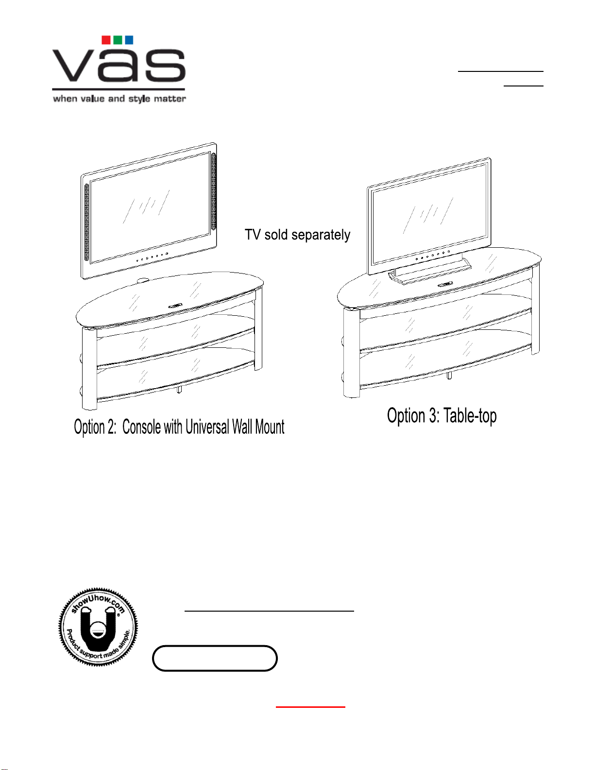
VAS 3 in 1 Flat Panel Console User manual

VAS
VAS XLOGT2254CR-GB User manual

VAS
VAS XLO2254CR-NV User manual

VAS
VAS 3-N-1 Gaming Theater User manual

VAS
VAS XL50-2MC User manual

VAS
VAS XL50-5GB User manual

VAS
VAS BBCXL505GB User manual
Popular Indoor Furnishing manuals by other brands

Regency
Regency LWMS3015 Assembly instructions

Furniture of America
Furniture of America CM7751C Assembly instructions

Safavieh Furniture
Safavieh Furniture Estella CNS5731 manual

PLACES OF STYLE
PLACES OF STYLE Ovalfuss Assembly instruction

Trasman
Trasman 1138 Bo1 Assembly manual

Costway
Costway JV10856 manual