Vega TS-11 User manual

www.vega-absolute.ru
NETWORK TESTER
VEGA TS-11
User Manual
User Manual contains information how to work with
LoRaWAN™ network autonomic tester Vega TS-11, and
also contains warranty terms and conditions and rules
for operating, storage and transportation
www.vega-absolute.ru


www.vega-absolute.ru
Document information
Title
Network tester Vega TS-11
Document type
Manual –translation from Russian
Document number
V02-TS11-01
Revision and date
02 –27.12.2017
This document applies to the following products:
Product name
Type number
End devices
Vega TS-11
Revision history
Revision
Date
Name
Comments
01
28.09.2017
КЕV
Document creation date
02
27.12.2017
KEV
New paragraphs at ‘Settings’ menu

Vega TS-11 / User Manual
2
Revision 02 - 27.12.2017
ОГЛАВЛЕНИЕ
1 DESCRIPTION AND OPERATION ...........................................................................................................................................3
2 SPECIFICATION............................................................................................................................................................................ 5
3 FAST NETWORK TESTING ........................................................................................................................................................6
4 DEVICE OPERATING................................................................................................................................................................... 7
User interface ............................................................................................................................................................................... 7
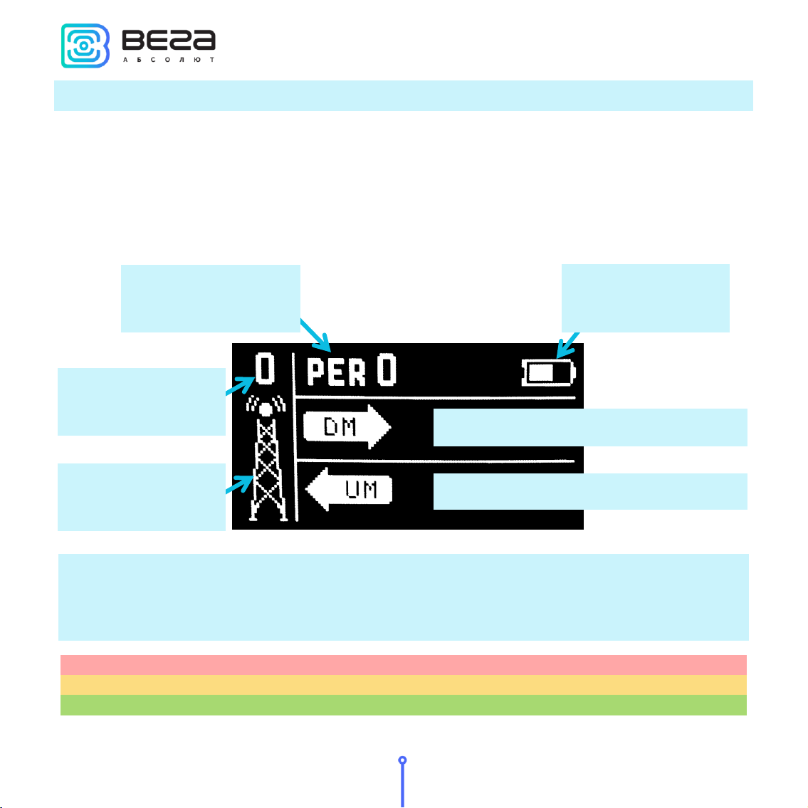
Work screen 1 –Uplink and Downlink demodulation margin ...................................................................................8
Work screen 2 –Full information about the network ................................................................................................12
Work screen 3 –Downlink signal RSSI and Uplink demodulation margin diagrams......................................15
Settings ......................................................................................................................................................................................... 17
Automatic test mode...............................................................................................................................................................19
Information .................................................................................................................................................................................19
Shutdown.................................................................................................................................................................................... 20
Battery charging....................................................................................................................................................................... 20
Firmware update ...................................................................................................................................................................... 20
5 STORAGE AND TRANSPORTATION REQUIREMENTS.................................................................................................23
6 CONTENT OF THE PACKAGE .............................................................................................................................................. 24
7 WARRANTY...................................................................................................................................................................................25

Vega TS-11 / User Manual
3
Revision 02 - 27.12.2017
1 DESCRIPTION AND OPERATION
Tester sends a special signal to the LoRaWAN™ network (‘Uplink’ packet), in response to
which the tester received a confirmation (‘Downlink’ packet).
Tester represents various information about network:
«Uplink»frequency –frequency on which the request sent to the network (MHz);
«Downlink»frequency - frequency on which the confirmation sent from the
network (MHz);
SF (spread factor) - coefficient determining the data rate of «Uplink» and
«Downlink»signals;
Tester’s transmitter power (dBm);
Requests number;
Network tester Vega TS-11 is
designed for testing LoRaWAN
networks while them is
deploying and setting up

Vega TS-11 / User Manual
4
Revision 02 - 27.12.2017
RSSI (Received signal strength indicator) –«Downlink» signal power (dBm);
Receiving window number at which confirmation was received (1 or 2);
UDM - Uplink demodulation margin (hereinafter UM);
DDM - Downlink demodulation margin (hereinafter DM);
PER (packet error rate) –relation of the received packets number to the total
number of sending packets expressed as a percentage;
Number of visible gateways.
Tester powered from rechargeable battery 550 mAh by which tester may work up to 16
hours.
Tester configured via self-interface ‘Settings’.

Vega TS-11 / User Manual
5
Revision 02 - 27.12.2017
2 SPECIFICATION
Main
Operating temperatures
-40…+85 °С
Display
OLED, 1,3”
USB-port
micro-USB, 5 V, 500 mA
LoRaWAN
LoRaWAN class
А
Antenna type
internal
Sensitivity
-138 dBm
Radio coverage in restrained urban conditions
Up to 5 km
Radio coverage within line of sight
Up to 15 km
Transmitter power
Up to 100 mW (configurable)
Power
Rechargeable battery
550 mAh
Case
Ingress protection rating
IP64
Housing dimensions
90 х 52 х 31 mm

Vega TS-11 / User Manual
6
Revision 02 - 27.12.2017
3 FAST NETWORK TESTING
Press ‘OK’
button
Press ‘Up’
button:
The first pressing
–connection to
the network, the
second –
network test
Gateways
number
Uplink demodulation
margin in dBm
Downlink demodulation
margin in dBm
Successful
transmissions in
percent
No signal / no
data

Vega TS-11 / User Manual
7
Revision 02 - 27.12.2017
4 DEVICE OPERATING
USER INTERFACE
Tester equipped with control buttons, sound speaker and OLED display. Every pressing
on the button accompaniment with sound signal if device sound is not off.
To common main menu it need to press ‘OK’ button while device is on. Menu appears
independent on what was on the display before button pressing.
‘Right’ and ‘Left’ buttons is using for navigating through the menu. Press ‘OK’ button for
select a menu item. Main menu contains the follow items:
Work screens –screens with the full information about the network.
Settings –tester settings screen.
Information –displays the keys and identifiers of the tester.
Shutdown –choose that item to switch device to low power consumption mode.
Battery charge –battery charge indicator.
Work screens
Information
Shutdown
Settings
Battery charge

Vega TS-11 / User Manual
8
Revision 02 - 27.12.2017
WORK SCREEN 1 –UPLINK AND DOWNLINK DEMODULATION MARGIN
First work screen appears just after device switch on. Herewith the data is not available on
it. Work screen 1 allows you to get the follow information:
Number of visible gateways;
PER coefficient –percent of successful transmissions;
Margin demodulation diagrams and numerical values of UM and DM of the last
session.
Margin demodulation is the positive integer value displayed in dBm and indicating how much
received signal above the demodulation threshold. ‘0’ value means that the packet was received
on the bottom of demodulation (0 dBm), whereas, for example, ‘20’ value means that the packet
was received on 20 dBm above the demodulation threshold.
from 0 to 5
Communication on the brink of failure, unstable connection to the network
from 5 to 10
Border zone, stable communication is not guaranteed
above 10
Good signal strength, confident communication
DM –Downlink Margin demodulation
UM –Uplink Margin demodulation
‘Gateway’ icon
Number of
gateways
Percent of successful
transmissions
Battery charge

Vega TS-11 / User Manual
9
Revision 02 - 27.12.2017
‘Gateway’ icon - displays the activity of the communication process as an animation.
Animation continues until the confirmation is accepted or the receiving window timeout expires.
Number of gateways - the number of gateways received the last packet from the
network tester successfully.
Percent of successful transmissions –PER (Packet error rate) coefficient is calculated as
the ratio of the number of confirmations received by the tester from the network to the total
number of requests, expressed as a percentage. It can vary from 0 (no one confirmation has
come, or PER is less than 1% and rounding up to integer) to 100% (the number of confirmations
is equal to the number of requests).
Battery charge –displays the current battery charge status. When the battery is critically
discharged, the icon becomes empty, flashes, and the tester emits a periodic beep. The
approximate remaining time of operation is not more than 5 minutes, it is necessary to charge
the battery.
The first time the ‘Up’button is pressed, the tester sends a request to the network to join
the network (hereinafter ‘join-request’), which is displayed on the UM (Uplink demodulation
margin) diagram as a shaded bar. If the tester is successfully connected to the network, a filled
bar appears in the DM diagram (Downlink demodulation margin).
Connection to the network is
successful –filled bar
Join-request, is displayed as a
shaded bar

Vega TS-11 / User Manual
10
Revision 02 - 27.12.2017
A shaded bar appears on the DM diagram if a failed attempt is made also. In total, the
network tester takes three attempts to join the network.
After successful joining the network, you can start testing the network. There are two
ways: manual and automatic. In the first case, the network tester sends an Uplink request to the
network each time the ‘Up’ button is pressed. In the automatic mode, the tester will send
requests itself with the period specified in settings, and also by pressing the ‘Up’button.
‘Hourglass’ icon –automatic mode indicator is located in the upper right corner of the
screen. If it is, automatic test mode is on, if not - off.
Three failed attempts
to join the network
DM diagram
UM diagram
‘Hourglass’ icon

Vega TS-11 / User Manual
11
Revision 02 - 27.12.2017
Diagrams DM and UM - the arrow indicates the direction of the radio signal propagation,
and the diagram shows the history of its change. The level of each bar on diagram shows the
demodulation margin of a particular packet. The latest (recent) radio communication is displayed
on the bar located next to the arrow. On the arrow is displayed the numerical value of the
demodulation margin in dBm of the latest radio communication. During the execution of new
communications, the diagram shifts to the right.
If the radio communication has not passed or the data has not been received, for
example, an error occurred during reception or the confirmation window timeout expires, the
shaded bar is displayed (that bar type has no level and occupies the entire amplitude of the
diagram).

Vega TS-11 / User Manual
12
Revision 02 - 27.12.2017
WORK SCREEN 2 –FULL INFORMATION ABOUT THE NETWORK
Switching between screens is carried out by pressing ‘Left’and ‘Right’ buttons. During the
testing process, you can freely navigate between them to get more complete information about
the network. Work screen 2 allows you to get the follow information:
PER coefficient –percent of successful transmissions;
Number of visible gateways;
Tester’s join status;
Number of packets transmitted by the tester - COUNT;
UM (demodulation margin), P(power), SF (spread factor) and FQ (frequency) of the
latest transmitted packet;
Receiving window number of the latest received confirmation - slot;
Number of packets received by the gateway - COUNT;
DM (demodulation margin), RSSI (signal level), SF (spread factor) and FQ
(frequency) of the latest received packet.
‘Antenna’ icon
‘Network’ icon
Percent of successful
transmissions
‘Hourglass’ icon
Status line
Parameters of the
latest packet
transmitted by
tester
Battery charge
receiving window №
Parameters of the
latest packet
received by tester
Title bar

Vega TS-11 / User Manual
13
Revision 02 - 27.12.2017
Unlike other screens, the work screen 2 displays information only about the last communication
session. The accumulated data here is the PER coefficient and the total number of received /
transmitted packets.
Percent of successful transmissions –PER (Packet error rate) coefficient is calculated as
the ratio of the number of confirmations received by the tester from the network to the total
number of requests, expressed as a percentage. It can vary from 0 (no one confirmation has
come, or PER is less than 1% and rounding up to integer) to 100% (the number of confirmations
is equal to the number of requests).
‘Network’ icon - has two states: joined / disconnected. Next to the icon, the network
capacity is displayed as a number of gateways that successfully received the latest packet from
the network tester.
Status line –the current transmission status is displayed in text form:
join TX –a request to join the network is performed;
join RX –reception of confirmation to a network connection request;
joined –the connection to the network was successful (the ‘Network’icon
changes its status);
link TX –‘Uplink’ request is performed;
link RX –reception of confirmation ‘Downlink’;
link OK –communication session was successful;
time-out –‘Downlink’ packet receiving window timeout expires;
error –communication session error.
‘Antenna’ icon –is located above the title bar and displays the moments of sending and
receiving packets as an animation.
Title bar –is located in the center of work screen. It is the list of displayed parameters. To
the left of the title bar there is transmitting information is displayed, to the right of the title bar
there is reception information.

Vega TS-11 / User Manual
14
Revision 02 - 27.12.2017
Parameters of the latest packet transmitted by tester –to the left of the title bar there is
information is displayed from top to bottom in order:
COUNT –total number of ‘Uplink’packets transmitted by the tester;
UM –demodulation margin of the latest transmitted ‘Uplink’packet;
P –power of network tester transmitter;
SF –Spread factor –the latest ‘Uplink’ packet transmitting rate indicator;
FQ –frequency on which the latest ‘Uplink’ packet transmits.
Parameters of the latest packet received by tester –to the right of the title bar there is
information is displayed from top to bottom in order:
COUNT –total number of ‘Downlink’packets received by the tester;
DM –demodulation margin of the latest transmitted ‘Downlink’packet;
RSSI –the latest ‘Downlink’ packet power expressed as dBm;
SF - Spread factor –the latest ‘Downlink’ packet transmitting rate indicator;
FQ - frequency on which the latest ‘Downlink’ packet transmits.
‘Hourglass’ icon –automatic test mode indicator is located in the upper right corner of
the screen. If it is, automatic test mode is on, if not - off.
Battery charge –displays the current battery charge status. When the battery is critically
discharged, the icon becomes empty, flashes, and the tester emits a periodic beep. The
approximate remaining time of operation is not more than 5 minutes, it is necessary to charge
the battery.
Receiving window №- in the first or second window the latest ‘Downlink’ packet was
received.

Vega TS-11 / User Manual
15
Revision 02 - 27.12.2017
WORK SCREEN 3 –DOWNLINK SIGNAL RSSI AND UPLINK DEMODULATION MARGIN
DIAGRAMS
Work screen 3 allows you to get the follow information:
RSSI (Received signal strength indicator) –‘Downlink’ signal power expressed as
dBm;
UM - demodulation margin of the latest transmitted ‘Uplink’packet expressed as
dBm;
The presence of lost packets.
Please note that screen 3 does not show the battery charge level, and there is no way to
enable / disable the automatic network testing mode.
The left side of the screen displays an RSSI diagram, and in the upper left corner the RSSI
value for the last received packet in dBm is shown. When a new packet is received, the diagram
shifts to the left, and the bar corresponding to the last received value appears on the right side.
The right part of the screen displays the ‘Uplink’packet demodulation diagram, and in
the upper right corner the UM value for the last transmitted packet is displayed. When a new
UM as dBmRSSI as dBm
UM diagram
(Uplink
demodulation
margin)
RSSI diagram
(Downlink
signal power)
‘Antenna’ icon

Vega TS-11 / User Manual
16
Revision 02 - 27.12.2017
packet is send, the diagram shifts to the right, and the bar corresponding to the last received
value appears on the left.
If the communication session was successful and the data was received, then the bar on
the diagram is filled with white color, if the session has not passed or the data is not received,
then the bar is shaded.
‘Antenna’ icon - displays moments of transmission and reception of packets as an
animation.

Vega TS-11 / User Manual
17
Revision 02 - 27.12.2017
SETTINGS
To go to the settings menu, you need to call up the main menu by clicking on the ‘OK’
button. Press the ‘Left’/ ‘Right’button to move the cursor to select the ‘Settings’icon and press
the ‘OK’button again. A screen with a list of settings appears.
Frequency plan –choice of the frequency standard. EUR –European frequency plan.
RUS –Russian frequency plan.
Adjust USER plan –while pressing the ‘Right’/’Left’ button an additional screen appears
on which you can set a custom frequency plan.
That screen is seems like below:
All settings are saved when the power
is turned off
Move through the settings menu - the
‘Up’/ ‘Down’buttons, change the
settings - the ‘Right’/ ‘Left’buttons
Move through the parameters list –
the ‘Up’/ ‘Down’buttons, parameter
choice –the ‘Right’/ ‘Left’buttons,
edit choosing value –the ‘Up’/
‘Down’buttons
Move on level above –the ‘OK’
button

Vega TS-11 / User Manual
18
Revision 02 - 27.12.2017
The custom frequency plan is limited in the range of 860-960 MHz. The data rate (DR) of the
second receiving window (RX2) can take values from 0 to 5, where 0 corresponds to spread
factor 12 (SF12).
ADR –allows to on/off an automatic data rate set of the ‘Uplink’ packet and the first
receiving window also. ADR parameter have not influence on the data rate of the second
receiving window.
Data rate –sets data rate of the ‘Uplink’ packet and the first receiving window while ADR
parameter is switched off and can vary from 0 to 5. When ADR parameter is switch on the first
attempt to join the network will initiates with this data rate value.
Device sound –switch on/off the network tester sound. ON –all sound signals is on. OFF
–all sound signals is off.
Logotype –logotype displaying while device is switching on. ON –logotype and
firmware version are displayed, OFF –no logotype and firmware version are displayed, there is
work screen 1 appears at once.
Auto-off minute –set timeout of automatic network tester switch off. Timeout sets in
minutes from 1 to 60. The timeout is restarted each time for the specified period by pressing any
button on the device. If no device button is pressed, then after timeout expired the network
tester goes to sleep mode, to save the battery power.
The auto-off function is deactivated during the device operates in the automatic test mode.
Request period –set automatic test mode period. The period may be equal to any value
from 30 seconds to 24 hours accurate to a second. There is the follow display format –
hours:minuts:seconds. One pressing on the ‘Right’ button will increase the counter by one
second. If you press the ‘Right’button and hold it, the counter will start increase by 1 minute. If
you hold the button for more than 5 seconds, the minutes counter will accelerate to 5 minutes
at a time and so on. After the value 24:00:00, the value 00:00:30 appears again. The ‘Left’button
decreases the counter value in the same way.
Table of contents
Other Vega Test Equipment manuals
Popular Test Equipment manuals by other brands

Gossen MetraWatt
Gossen MetraWatt DUSPOL analog 1000 operating manual

Halma
Halma Ocean Optics AR-1 Installation and operation instructions

Viavi
Viavi AVX-10K Getting started guide

YATO
YATO YT-7300 quick guide

2B Technologies
2B Technologies Model 408 Operation manual

Hanna Instruments
Hanna Instruments HI 3830 instruction manual