Vega VEGAMET 625 User manual

Operating Instructions
Signal conditioning and display
instrument for level sensors
VEGAMET 625
Double channel HART
Document ID: 28970

2
Contents
VEGAMET 625 • Double channel HART
28970-EN-130701
Contents
1 About this document
1.1 Function ........................................................................................................................... 4
1.2 Target group ..................................................................................................................... 4
1.3 Symbolism used............................................................................................................... 4
2 For your safety
2.1 Authorised personnel ....................................................................................................... 5
2.2 Appropriate use................................................................................................................ 5
2.3 Warning about incorrect use............................................................................................. 5
2.4 General safety instructions............................................................................................... 5
2.5 Safety label on the instrument .......................................................................................... 5
2.6 CE conformity................................................................................................................... 6
2.7 Safety instructions for Ex areas ........................................................................................ 6
2.8 OverllprotectionaccordingtoWHG ............................................................................... 6
2.9 Environmental instructions ............................................................................................... 6
3 Product description
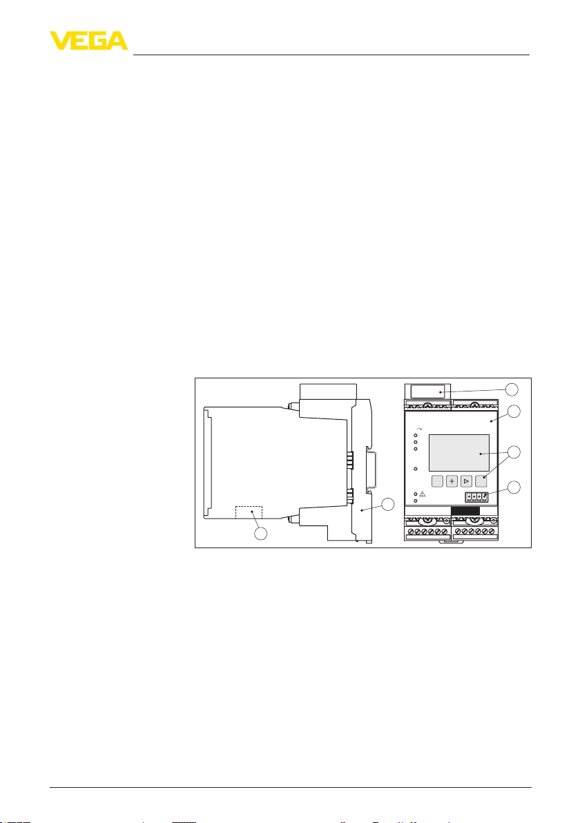
3.1 Conguration.................................................................................................................... 7
3.2 Principle of operation........................................................................................................ 8
3.3 Adjustment ....................................................................................................................... 8
3.4 Packaging, transport and storage..................................................................................... 9
4 Mounting
4.1 General instructions ....................................................................................................... 10
4.2 Mounting instructions ..................................................................................................... 10
5 Connecting to power supply
5.1 Preparing the connection ............................................................................................... 12
5.2 Connection procedure.................................................................................................... 12
5.3 Wiring plan ..................................................................................................................... 14
6 Setup with the integrated display and adjustment unit
6.1 Adjustment system......................................................................................................... 16
6.2 Setup steps .................................................................................................................... 17
6.3 Menu schematic............................................................................................................. 27
7 Setup with PACTware
7.1 Connect the PC.............................................................................................................. 35
7.2 Parameter adjustment with PACTware............................................................................ 37
7.3 Setup web server/e-mail, remote enquiry....................................................................... 38
8 Application examples
8.1 Levelmeasurementinacylindricaltankwithoverllprotection/dryrunprotection ......... 39
8.2 Weir control of a water power station.............................................................................. 40
8.3 Interface measurement with VEGAFLEX........................................................................ 42
8.4 Pump control 1/2 (running time controlled)..................................................................... 43
8.5 Tendency recognition ..................................................................................................... 45
8.6 Flow measurement......................................................................................................... 46
9 Maintenanceandfaultrectication
9.1 Maintenance .................................................................................................................. 49
9.2 Rectify faults................................................................................................................... 49
9.3 Instrument repair ............................................................................................................ 51

3
Contents
VEGAMET 625 • Double channel HART
28970-EN-130701
10 Dismounting
10.1 Dismounting steps.......................................................................................................... 52
10.2 Disposal ......................................................................................................................... 52
11 Supplement
11.1 Technical data ................................................................................................................ 53
11.2 Overview applications/functionality ................................................................................ 55
11.3 Dimensions .................................................................................................................... 57
Supplementary documentation
Information:
Supplementary documents appropriate to the ordered version come
withthedelivery.Youcanndthemlistedinchapter"Product descrip-
tion".
Editing status: 2013-06-18

4
1 About this document
VEGAMET 625 • Double channel HART
28970-EN-130701
1 About this document
1.1 Function
This operating instructions manual provides all the information you
need for mounting, connection and setup as well as important instruc-
tionsformaintenanceandfaultrectication.Pleasereadthisinforma-
tion before putting the instrument into operation and keep this manual
accessible in the immediate vicinity of the device.
1.2 Target group
This operating instructions manual is directed to trained specialist
personnel.The contents of this manual should be made available to
these personnel and put into practice by them.
1.3 Symbolism used
Information, tip, note
This symbol indicates helpful additional information.
Caution: If this warning is ignored, faults or malfunctions can result.
Warning: If this warning is ignored, injury to persons and/or serious
damage to the instrument can result.
Danger: If this warning is ignored, serious injury to persons and/or
destruction of the instrument can result.
Ex applications
This symbol indicates special instructions for Ex applications.
• List
The dot set in front indicates a list with no implied sequence.
→ Action
This arrow indicates a single action.
1 Sequence of actions
Numbers set in front indicate successive steps in a procedure.
Battery disposal
This symbol indicates special information about the disposal of bat-
teries and accumulators.

5
2 For your safety
VEGAMET 625 • Double channel HART
28970-EN-130701
2 For your safety
2.1 Authorised personnel
All operations described in this operating instructions manual must
be carried out only by trained specialist personnel authorised by the
plant operator.
During work on and with the device the required personal protective
equipment must always be worn.
2.2 Appropriate use
VEGAMET 625 is a universal signal conditioning instrument and
power supply unit for connection of two HART sensors.
Youcannddetailedinformationontheapplicationrangeinchapter
"Product description".
Operational reliability is ensured only if the instrument is properly
usedaccordingtothespecicationsintheoperatinginstructions
manual as well as possible supplementary instructions.
For safety and warranty reasons, any invasive work on the device
beyond that described in the operating instructions manual may be
carried out only by personnel authorised by the manufacturer. Arbi-
traryconversionsormodicationsareexplicitlyforbidden.
2.3 Warning about incorrect use
Inappropriate or incorrect use of the instrument can give rise to
application-specichazards,e.g.vesseloverllordamagetosystem
components through incorrect mounting or adjustment.
2.4 General safety instructions
This is a high-tech instrument requiring the strict observance of stand-
ard regulations and guidelines. The user must take note of the safety
instructionsinthisoperatinginstructionsmanual,thecountry-specic
installation standards as well as all prevailing safety regulations and
accident prevention rules.
Theinstrumentmustonlybeoperatedinatechnicallyawlessand
reliable condition.The operator is responsible for trouble-free opera-
tion of the instrument.
During the entire duration of use, the user is obliged to determine the
compliance of the necessary occupational safety measures with the
current valid rules and regulations and also take note of new regula-
tions.
2.5 Safety label on the instrument
The safety approval markings and safety tips on the device must be
observed.

6
2 For your safety
VEGAMET 625 • Double channel HART
28970-EN-130701
2.6 CE conformity
ThedevicefulllsthelegalrequirementsoftheapplicableECguide-
lines.ByaxingtheCEmarking,weconrmsuccessfultestingofthe
product.
YoucanndtheCECerticateofConformityinthedownloadsection
of our homepage.
Electromagnetic compatibility
The instrument is designed for use in an industrial environment.
Nevertheless, electromagnetic interference from electrical conductors
and radiated emissions must be taken into account, as is usual with a
class A instrument according to EN 61326-1. If the instrument is used
inadierentenvironment,itselectromagneticcompatibilitywithother
devices must be ensured by suitable measures.
2.7 Safety instructions for Ex areas
PleasenotetheEx-specicsafetyinformationforinstallationandop-
eration in Ex areas. These safety instructions are part of the operating
instructions manual and come with the Ex-approved instruments.
2.8 OverllprotectionaccordingtoWHG
InGermanytheWHG(WaterResourceAct)stipulatesanoverll
protectionforsystemsthatdealwithsubstanceshazardoustowater.
Anappropriatelycertiedsensoristheprerequisiteforsuchprotec-
tion.TheVEGAMET625fullstheconstructionandtestingprinciples
foroverllprotectionsystems.ThisiscertiedbytheTÜV(Techni-
calControlBoard)statement"PP 5003/09".Youcandownloadthis
documentfromourhomepageunder"Downloads - Approvals - Signal
conditioning instruments - Overll protection".
2.9 Environmental instructions
Protection of the environment is one of our most important duties.
That is why we have introduced an environment management system
with the goal of continuously improving company environmental pro-
tection.Theenvironmentmanagementsystemiscertiedaccording
to DIN EN ISO 14001.
Pleasehelpusfulllthisobligationbyobservingtheenvironmental
instructions in this manual:
• Chapter"Packaging, transport and storage"
• Chapter"Disposal"

7
3 Product description
VEGAMET 625 • Double channel HART
28970-EN-130701
3 Product description
3.1 Conguration
The scope of delivery encompasses:
• VEGAMET 625 signal conditioning instrument
• Terminal socket
• Coded pins and bridges
• RS232 modem connection cable (optional)
• Documentation
– this operating instructions manual
– Supplementaryinstruction30325"RS232/Ethernet connection"
(optional)
– Supplementaryinstructionsmanual30768"Modbus-TCP,
VEGA ASCII protocol"(optional)
– Ex-specic"Safety instructions"(withExversions)
– ifnecessary,furthercerticates
The VEGAMET 625 consists of the components:
• VEGAMET 625 signal conditioning instrument with display and
adjustment unit in the front
• Terminal socket
VEGAMET
12 34
9101112
17 18 20 21 22
56 78
13 14 15 16
23 24 25 26 27 28
Ser. No.
12345678
on
OK
ESC
COM
3
2
1
2
3
4
1
6
5
Fig. 1: VEGAMET 625
1 Ex separating chamber with Ex version
2 VEGAMET 625
3 Display and adjustment unit
4 Communication interface for VEGACONNECT (I²C)
5 RS232 or Ethernet interface (optional)
6 Terminal socket
Thenameplatecontainsthemostimportantdataforidenticationand
use of the instrument:
• Article number
• Serial number
• Technical data
• Article numbers, documentation
Scope of delivery
Constituent parts
Type plate

8
3 Product description
VEGAMET 625 • Double channel HART
28970-EN-130701
The order data and the documentation of the instrument can be
retrieved by means of the instrument serial number on the type label.
To do this, go to www.vega.com,"VEGA Tools"and"serial number
search".
3.2 Principle of operation
VEGAMET 625 is a universal signal conditioning instrument for a
number of applications such as level, gauge, interface and process
pressure measurement. At the same time, it can serve as power
supply unit for connected sensors. VEGAMET 625 is designed for
connection of two independent VEGA HART sensors. Hence two
independent measurements can be carried out. By means of a third
measurementloop,thedierencebetweenthetwoinputvaluescan
be calculated.
On instruments with one of the optional interfaces (RS232/Ethernet),
the measured values can be retrieved via modem or network and dis-
played by means of a web browser, Visual VEGA or WEB-VV. It is also
possible to send measured values and messages via e-mail. The use
of VEGAMET 625 is particularly suitable for stocktaking, VMI (Vendor
Managed Inventory) and remote enquiry.
The VEGAMET 625 signal conditioning instrument can power two
HART sensors and process their measured signals via the same
cable.The measured value transmission is carried out via a digital
bus system (HART Multidrop). The requested parameter is displayed
and also sent to the integrated current outputs for further processing.
Hence the measured signal can be transferred to a remote indication
or a superordinate control system. Three level relays for control of
pumps or other actuators are also integrated.
Wide-range power supply unit with 20 … 253 V AC/DC for world-wide
use.
Detailed information about the power supply can be found in chapter
"Technical data".
3.3 Adjustment
The instrument can be adjusted with the following adjustment media:
• With integrated display and adjustment unit
• an adjustment software according to FDT/DTM standard, e.g.
PACTware and a Windows PC
The entered parameters are generally saved in VEGAMET 625, when
used with PACTware and PC also optionally in the PC.
Information:
When using PACTware and the corresponding VEGA DTM, additional
settings can be carried out which are not possible or only partly pos-
sible with the integrated display and adjustment unit. When using an
adjustment software, you either need one of the integrated interfaces
(RS232/Ethernet) or the interface converter VEGACONNECT.
Application area
Functional principle
Voltage supply

9
3 Product description
VEGAMET 625 • Double channel HART
28970-EN-130701
Further instructions for setting up the web server and e-mail functions
can be found in the online help of PACTware or the VEGAMET 625
DTMsaswellastheoperatinginstructionsmanual"RS232/Ethernet
connection".
3.4 Packaging, transport and storage
Your instrument was protected by packaging during transport. Its
capacity to handle normal loads during transport is assured by a test
based on ISO 4180.
The packaging of standard instruments consists of environment-
friendly, recyclable cardboard. For special versions, PE foam or PE
foil is also used. Dispose of the packaging material via specialised
recycling companies.
Transport must be carried out under consideration of the notes on the
transport packaging. Nonobservance of these instructions can cause
damage to the device.
The delivery must be checked for completeness and possible transit
damage immediately at receipt. Ascertained transit damage or con-
cealed defects must be appropriately dealt with.
Up to the time of installation, the packages must be left closed and
stored according to the orientation and storage markings on the
outside.
Unless otherwise indicated, the packages must be stored only under
the following conditions:
• Not in the open
• Dry and dust free
• Not exposed to corrosive media
• Protected against solar radiation
• Avoiding mechanical shock and vibration
• Storageandtransporttemperatureseechapter"Supplement -
Technical data - Ambient conditions"
• Relative humidity 20 … 85 %
Packaging
Transport
Transport inspection
Storage
Storage and transport
temperature

10
4 Mounting
VEGAMET 625 • Double channel HART
28970-EN-130701
4 Mounting
4.1 General instructions
Each series 600 instrument consists of the actual signal conditioning
instrument as well as a plug-in socket for carrier rail mounting (top-
hat rail 35 x 7.5 according to DIN EN 50022/60715). Because it has
protection class IP 30 or IP 20, the instrument is intended to be used
in switching cabinets.
4.2 Mounting instructions
The plug-in socket is designed for carrier rail mounting. The operat-
ing voltage is connected to terminals 17 and 18. For neighbouring
series 600 instruments it is possible to continue connection L1 and
Ndirectlyviathesuppliedbridges.Max.veinstrumentscanbecon-
nected through in this way.
Danger:
Looping through via bridges is only allowed for operating voltage
(sockets L1 and N).The bridges must never be used with single
instruments, at the end of a row of instruments or with other sockets.
If this rule is not heeded, there is a danger of coming into contact with
the operating voltage or causing a short circuit.
A VEGAMET 625 in Ex version is an auxiliary, intrinsically safe instru-
ment and may not be installed in explosion-endangered areas.
Before setup, the Ex separating chamber must be attached (as shown
below) with Ex versions. Safe operation can be only ensured if the
operatinginstructionsmanualandtheEGtypeapprovalcerticate
are observed.VEGAMET 625 must not be opened.
Allsignalconditioninginstrumentsareprovidedwithdierentgaps
dependent on type and version (mechanical coding).
The plug-in socket is provided with coded pins that can be inserted to
prevent accidental interchanging of the various instrument types.
With a VEGAMET 625 in Ex version, the supplied coded pins (type
coded pin and Ex coded pin) must be inserted by the user according
to the below chart.
Installation possibilities
Mounting
Instrument coding

11
4 Mounting
VEGAMET 625 • Double channel HART
28970-EN-130701
A o
B o
C o
1 o
2 o
3 o
o
o
o
7 o
8 o
9 o
o
o
12 o
N
L1
VEGA A o
B o
C o
1 o
2 o
3 o
4 o
5 o
6 o
7 o
8 o
9 o
10 o
11 o
12 o
N
L1
VEGA
12345678
1
4 4
2
3
Fig. 2: Plug-in socket VEGAMET 625
1 Ex separating chamber
2 Ex coding with Ex version
3 Type coding for VEGAMET 624/625
4 Bridges for looping the operating voltage

12
5 Connecting to power supply
VEGAMET 625 • Double channel HART
28970-EN-130701
5 Connecting to power supply
5.1 Preparing the connection
Always keep in mind the following safety instructions:
• Connect only in the complete absence of line voltage
• If overvoltage surges are expected, overvoltage arresters should
be installed
Inhazardousareasyoumusttakenoteoftherespectiveregulations,
conformityandtypeapprovalcerticatesofthesensorsandpower
supply units.
Thevoltagesupplycanbe20…253VAC/DC,50/60Hz.
The operating voltage of VEGAMET 625 is connected with standard
cable according to the national installation standards.
Standard two-wire cable can be used for connecting the sensors. The
screening is absolutely necessary to ensure interference-free opera-
tion with HART sensors.
Connect the cable screen on both ends to ground potential. In the
sensor, the screen must be connected directly to the internal ground
terminal. The ground terminal on the outside of the sensor housing
must be connected to the potential equalisation (low impedance).
If potential equalisation currents are expected, the screen connection
on the side of VEGAMET 625 must be made via a ceramic capacitor
(e. g. 1 nF, 1500 V). The low frequency potential equalisation currents
arethussuppressed,buttheprotectiveeectagainsthighfrequency
interference signals remains.
Take note of the corresponding installation regulations for Ex applica-
tions. In particular, make sure that no potential equalisation currents
owoverthecablescreen.Incaseofgroundingonbothsidesthis
can be achieved by the use of a capacitor or a separate potential
equalisation.
5.2 Connection procedure
Note:
Before the actual setup, each HART sensors must be assigned an
address(addressrange1-15),(seechapter"Setup").Address0
(mode 4 … 20 mA) must not be used. When assigning an address,
only one sensor should be connected to VEGAMET 625. If connec-
tioniscompletedalready,thewiringmustbebrieycancelledfor
addressing. Depending on the installation location of the sensors, it
can be advantageous to carry out this addressing before installing
and connecting the sensors.This can be conveniently carried out
e.g. in the workshop.You just need a 24 Volt power supply as well as
an indicating and adjustment module PLICSCOM or the adjustment
software PACTware with VEGACONNECT.
Move on to electrical connection and proceed as follows:
1. Snap the socket without VEGAMET 625 onto the carrier rail
Note safety instructions
Take note of safety
instructions for Ex
applications
Select power supply
Select connection cable
Cable screening and
grounding
Select connection
cable for Ex applica-
tions

13
5 Connecting to power supply
VEGAMET 625 • Double channel HART
28970-EN-130701
2. Connect sensor cable to terminal 1/2 (active input) or 3/4 (passive
input), provide a screening
3. When using several sockets, loop the power supply by means of
bridges
4. Connectpowersupply(switchedo)toterminal17and18
5. If necessary, connect relays or other outputs
6. Insert VEGAMET 625 into the plug-in socket and screw it down
tightly
Note:
If the addressing of the sensors has not yet been carried out, only one
sensormustbeconnected.Addressing(seechapter"Setup")ofthe
rstsensorcanthenbecarriedout.Afterwards,therstsensormust
be disconnected again and the next sensor connected and provided
with an address.Then all sensors can be connected and setup can
be started.
Before setting up Ex versions, make sure the Ex separating chamber
is plugged on the left housing side (above the sensor terminals). The
pins for type and Ex coding must also be inserted correctly.
Information:
• On the active input (terminal 1/2), VEGAMET 625 provides power
for the connected sensors. Power supply and measurement data
are transmitted over the same two-wire cable.This mode is pro-
vided for connection of measuring transducers without separate
operating voltage (sensors in two-wire version).
• On the passive input (terminals 3/4), the sensors are not supplied
with energy - only the measured value is transmitted. This input is
for instruments with their own separate operating voltage (sensors
in four-wire version or separators such as VEGATRENN 149). On
a VEGAMET 625 in Ex version, the passive input is not available
due to approval/technical reasons.
Note:
VEGAMET 625 is designed for connection of two HART sensors.
BecausetheyareaccessedviadierentaddressesintheHART
multidrop mode, both sensors are connected to the same sensor
input.These are either terminals 1/2 (active input) or terminals 3/4
(passive input). Simultaneous mixed operation on active and passive
input is not possible.The measured value transmission is carried out
via the digital HART signal. An analogue 4 … 20 mA transmission is
not possible. Because this is a digital bus system, only one two-wire
cable should lead to the two sensors. A distributor can be connected
directly in front of the sensors. As an alternative, the connection to
the next sensor can be continued via the second cable entry in the
sensor housing.The addressing of the sensors should be carried out
beforeconnection,seechapter"Set up".

14
5 Connecting to power supply
VEGAMET 625 • Double channel HART
28970-EN-130701
5.3 Wiring plan
17 18 19 20 21 22
9101112
1
234
23 24 25 26 27 28
13 14 15 16
56 78
L1 N
+
-
+- +- +-
+-
17 2 3
4 5 6
+-
1211
13
8
9
10
Fig. 3: Wiring plan VEGAMET 625 with two-wire sensors
1 Internal operating relay 1
2 Internal operating relay 2
3 Internal operating relay 3
4 Internal current output 1
5 Internal current output 2
6 Internal current output 3
7 Voltage supply of VEGAMET 625
8 Measurement data input with sensor supply (active input)
9 Measurement data input (passive input), not in Ex ia
10 Internal fail safe relay
11 HART two-wire sensor with Multidrop address 1
12 HART two-wire sensor with Multidrop address 2
13 Distributor
Wiring plan for two-wire
sensors

15
5 Connecting to power supply
VEGAMET 625 • Double channel HART
28970-EN-130701
17 18 19 20 21 22
9101112
1
234
23 24 25 26 27 28
13 14 15 16
56 78
L1 N
+
-
+- +- +-
+-
17 2 3
8
9
4 5 6
+-
1211
14
13
10
Fig. 4: Wiring plan VEGAMET 625 with four-wire sensors
1 Internal operating relay 1
2 Internal operating relay 2
3 Internal operating relay 3
4 Internal current output 1
5 Internal current output 2
6 Internal current output 3
7 Voltage supply of VEGAMET 625
8 Measurement data input with sensor supply (active input)
9 Measurement data input (passive input), not in Ex ia
10 Internal fail safe relay
11 HART four-wire sensor with Multidrop address 1
12 HART four-wire sensor with Multidrop address 2
13 Distributor
14 Power supply for four-wire sensors
Wiring plan for four-wire
sensors

16
6 Setup with the integrated display and adjustment unit
VEGAMET 625 • Double channel HART
28970-EN-130701
6 Setup with the integrated display and
adjustment unit
6.1 Adjustment system
The integrated display and adjustment unit is used for measured
value display, adjustment and diagnosis of VEGAMET 625 as well as
the connected sensors.The indication and adjustment are carried out
via four keys and a clear, graphic-capable display with background
lighting. The adjustment menu with selectable language is clearly
structured and enables easy setup.
Certain adjustment options are not possible or only partially available
with the integrated display and adjustment unit, e.g. settings for the
e-mail server. For such applications, the use of PACTware with ap-
propriate DTMs is recommended.
Ser. No.
12345678
on
OK
ESC
COM
3
2
1
3
6
5
7
4
1
2
Fig. 5: Display and adjustment elements
1 LC display
2 Adjustment keys
3 Communication interface for VEGACONNECT
4 Status indication operation
5 Status indication fail safe relay
6 Status indication interface activity
7 Status indication operating relay 1 - 3
• [OK] key:
– Move to the menu overview
– Conrmselectedmenu
– Edit parameter
– Save value
• [->] key to select:
– Menu change
– Select list entry
– Select editing position
• [+] key:
– Change value of the parameter
• [ESC] key:
– Interrupt input
Function
Display and adjustment
elements
Key functions

17
6 Setup with the integrated display and adjustment unit
VEGAMET 625 • Double channel HART
28970-EN-130701
– Jump to next higher menu
Note:
Approx. 10 minutes after the last pressing of a key, an automatic reset
tomeasuredvalueindicationistriggered.Anyvaluesnotconrmed
with [OK] will not be saved.
6.2 Setup steps
Through parameter adjustment, the instrument is adapted to the indi-
vidual application conditions. A measurement loop calibration is the
most important step and should always be carried out. A scaling of
the measured value to the desired physical variable and unit, possibly
includingalinearizationcurve,isoftenuseful.Theadaptationofthe
relay switching points or the setting of an integration time to smooth
the measured value are further standard adjustment options.
Instruments with Ethernet interface can be provided with a Host name
suitable for the measurement loop. As an alternative to the addressing
via DHCP, it is also possible to adjust an IP address and subnet mask
suitable for your network. If necessary, the e-mail/Web server can be
alsoconguredwithPACTware.
Information:
When using PACTware and the corresponding VEGA DTM, additional
settings can be carried out which are not possible or only partly pos-
sible with the integrated display and adjustment unit. When using an
adjustment software, you either need one of the integrated interfaces
(RS232/Ethernet) or the interface converter VEGACONNECT.
Further instructions for setting up the web server and e-mail functions
are stated in the online help of PACTware or the VEGAMET 625 DTMs
aswellasthesupplementaryinstructionsmanual"RS232/Ethernet
connection".
VEGAMET 625 can process measured values of more than one
HART sensor.The measured values are transmitted as digital HART
signals to the same cable (bus). An analogue 4 … 20 mA transmis-
sion is not possible, the current is limited to 4 mA. An own, unam-
biguous address (address range 1-15) must be assigned to each
connected sensor. This mode is also called HART multidrop mode.
Address 0 (mode 4 … 20 mA) must not be used.
Note:
When addresses are being assigned, only one sensor must be con-
nected on the bus. If this is not the case, no sensor can be accessed
and it is not possible to assign an address.
The addressing can be carried out directly on each HART sensor via
the respective adjustment unit or adjustment software. As an alterna-
tive, the setting of the sensor address can be also carried out via the
VEGAMETmenuunder"Service - Sensor address"(seechapter
"Setup procedure"under"Service - Change sensor address").
Parameter adjustment
SetHARTaddress

18
6 Setup with the integrated display and adjustment unit
VEGAMET 625 • Double channel HART
28970-EN-130701
Afterbeingswitchedon,VEGAMET625rstofallcarriesoutashort
self-check.The following steps are carried out:
• Internal check of the electronics
• indicationoftheinstrumenttype,rmwareversionaswellasthe
instrument TAG (instrument name)
• Theoutputsignalsjumpbrieytothesetfaultvalue
After the assignment of the addresses to the sensors, the current
measured values will be displayed and outputted.
As requested, the measured value display shows the individual
measurement loops separately or in a joint overview. The respective
digital display value, the measurement loop name (meas. loop TAG)
and the unit are shown.With the separate presentation, an analogue
bar graph is also displayed and the measured values appear in big-
gerfontsize.Bypushingthe[>]key,youmovebetweenthedierent
indicating options.
Note:
Dependingonthecongurationanduseofallmeasurementloops,
thecycletimeforthemeasuredvaluetransmissioncantakeuptove
seconds.
By pushing [OK] you move from the measured value indication to the
main menu.
The main menu is divided into six areas with the following functions:
• Device settings: Includes the device-TAG, settings for network
connection such as date/time setting, …
• Measurement loop: Includes settings for input selection, adjust-
ment,damping,linearization,scaling,outputs,…
• Display: Includes settings to the displayed measured value
• Diagnosis Includes information to the device status, error mes-
sages
• Service Includes simulation, reset, PIN, selectable language,
sensor address, …
• Info: Shows serial number, software version, last change, instru-
ment features, MAC addr., …
Switch-on phase
Measured value indica-
tion
Main menu

19
6 Setup with the integrated display and adjustment unit
VEGAMET 625 • Double channel HART
28970-EN-130701
→ Selectthemenuitem"Device settings"with[->]andconrmwith
[OK].
Underthemenuitem"Device settings",youcanselecttherequested
application.Foralllevel,gaugeanddierentialmeasurements,the
application"Standard"iscorrect.
If an interface measurement should be carried out with a VEGAFLEX
67,youhavetochoosethemenuitem"Interface measurement"as
application.Afterthecongurationoftheinputs,theexactdielectric
gurefortheuppermediummustbeentered.Forfurtherinformation
seechapter"Application examples".
→ Select the requested application with [->] and save your setting
with [OK].Finallychangetothemenuitem"Input"with[->].
Because VEGAMET 625 has two inputs, the measurement loops
must be assigned to the inputs. After the addresses of the HART sen-
sors are assigned, a list of the existing sensors can be prepared and
displayedvia"Sensor selection - Sensor search".Nowyoucanassign
the requested sensor to each measurement loop.
Fortransmission,VEGAMET625mustbeinformedwhich"Sensor
value"shouldbeusedforfurtherprocessing.Dependingonthesen-
sor type this can be distance, pressure, interface or temperature.You
willndfurtherinformationunderthemenuitem"Meas. loop - Input".
→ Allocate the requested inputs to the appropriate measurement
loops, select the suitable sensor value and save your settings with
[OK].Aftertherstsetup,youcanmodifytheinputsalsounder
"Meas. loop - Input".
You can assign an unambiguous name to VEGAMET 625 via the
Device-TAG. This function is recommended when several instruments
are implemented and a good documentation of larger systems is
required.
→ Enter the requested values via the appropriate keys and save
your settings with [OK].
For instruments with integrated Ethernet interface, the automatic
addressing via DHCP is preset, i.e. the IP address must be assigned
by a DHCP server. Generally the instrument is contacted via the Host
Device settings - Applica-
tion
Device settings - Input
Device settings - Device-
TAG
Devicesettings-Host
Name/IP addr.

20
6 Setup with the integrated display and adjustment unit
VEGAMET 625 • Double channel HART
28970-EN-130701
name. By default, the host name consists of the serial number plus
"VEGA-"infront.Asanalternative,itisalsopossibletoenterastatic
IP addr. with Subnet mask and optional Gateway addr.
Note:
Keepinmindthatyourmodicationwillbeonlyeectiveafterarestart
ofVEGAMET625.Youcanndfurtherinformationofthesenetwork
parametersinthesupplementaryinstructions"RS232/Ethernet con-
nection"andintheOnlinehelpoftherespectiveDTM.
Carry out your settings via the appropriate keys and save with [OK].
→ Carry out your settings via the appropriate keys and save with
[OK].Disconnectbrieytheoperatingvoltagesothatthemodi-
edsettingsbecomeeective.
Date and time can be entered in this menu item for instruments with
integratedRS232/Ethernetinterface.Thesetimesettingsarebuered
in case of power failure for approx. 3 days.
→ Enter the values via the appropriate keys and save your settings
with [OK].
For instruments with integrated RS232 interface, you determine here
which mode this serial interface should operate in.The following op-
tions are available:
• VVO protocol: Direct standard connection between signal condi-
tioning instrument and PC for parameter adjustment and enquiry
(e.g. with PACTware and DTM)
• PPP: Dial-up connection between signal conditioning instrument
and modem for independent transmission of e-mails (dial-out con-
nection) or enquiry via web browser (dial-in connection)
• ASCII protocol: Direct standard connection between signal con-
ditioning instrument and PC for enquiry with terminal programs,
e.g. Hyperterminal
→ Carry out your settings via the respective keys and save with
[OK]. Further information is available in the supplementary
Device settings - Time/
Date
Device settings - Commu-
nication protocol
Other manuals for VEGAMET 625
3
This manual suits for next models
6
Table of contents
Other Vega Test Equipment manuals