VESTEL EVC04 Series User manual

ELECTRIC VEHICLE CHARGER
EVC04 Series
User Manual
Användarmanual

English - 1IB v7.3.1 11.2021 © 2021 Vestel - All rights reserved
Contents
1 - SAFETY INFORMATION.................................................................................................................3
1.1 - SAFETY WARNINGS......................................................................................................3
1.2 - GROUND CONNECTION WARNINGS...........................................................................4
1.3 - POWER CABLES, PLUGS and CHARGING CABLE WARNINGS.................................4
1.4 - WALL MOUNTING WARNINGS....................................................................................4
2 - GENERAL INFORMATION................................................................................................................5
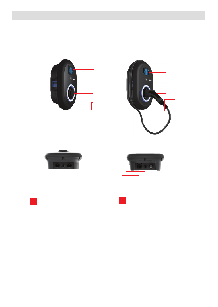
2.1 - INTRODUCTION OF THE PRODUCT COMPONENTS..................................................5
2.2 - PLUG CHARGING CABLE.............................................................................................6
2.2.1 - SOCKET EQUIPPED MODEL....................................................................6
2.2.2 - ATTACHED CABLE MODEL.....................................................................6
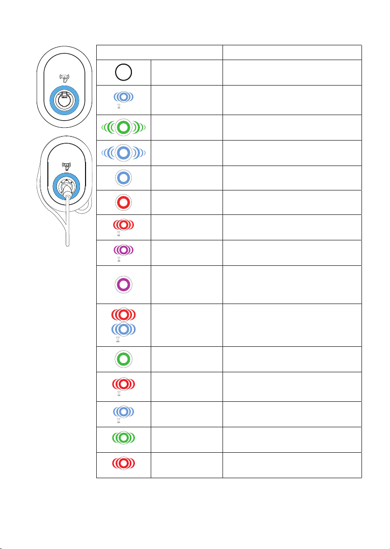
2.3 - BEHAVIOUR OF THE STATUS INFORMATION LED....................................................7
3 - DESCRIPTION..................................................................................................................................8
3.1 - MODEL DESCRIPTION................................................................................................8
3.2 - MODEL REFERENCES................................................................................................9
4 - TECHNICAL SPECIFICATION........................................................................................................9
5 - CHARGING....................................................................................................................................11
5.1 - PRODUCT VARIANTS.................................................................................................11
5.1.1 - Default Setting “Standalone”..................................................................11
5.1.2 - Default Setting “E.ON Auto-Detect”.....................................................12
5.2 - PRESET SELECTION.................................................................................................12
5.3 - PRESETS....................................................................................................................13
5.4 - STANDALONE USAGE MODES...................................................................................14
5.4.1 - AUTOSTART (PLUG&CHARGE) MODE .................................................15
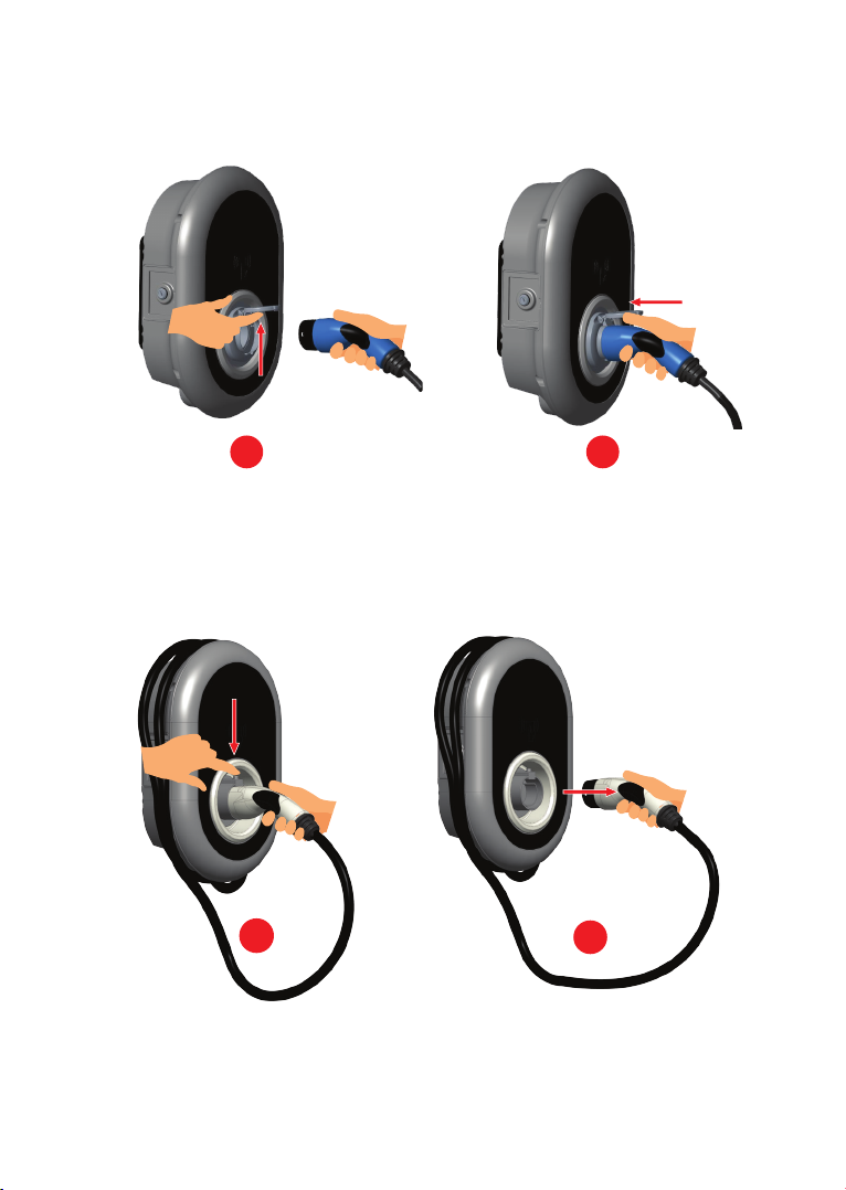
5.4.1.1 - SOCKET EQUIPPED MODEL...............................................15
5.4.1.1.1 - VEHICLE CONNECTION & CHARGING...........15
5.4.1.1.2 - STOP CHARGING............................................16
5.4.1.2 - ATTACHED CABLE MODEL..................................................17
5.4.1.2.1 - VEHICLE CONNECTION & CHARGING............17
5.4.1.2.2 - STOP CHARGING...............................................18
5.4.2 -RFID AUTHORIZATION MODE ..............................................................18
5.4.2.1 - ADD USER RFID CARD TO CHARGING STATION ..............19
5.4.2.2 - VEHICLE CONNECTION & CHARGING..............................19
5.4.2.2.1 - SOCKET EQUIPPED MODEL.............................................19
5.4.2.2.1.1 - VEHICLE CONNECTION & CHARGING........19
5.4.2.2.1.2 - STOP CHARGING.........................................21
5.4.2.2.2 - ATTACHED CABLE MODEL.............................................22
5.4.2.2.2.1 - VEHICLE CONNECTION & CHARGING.........22

English - 2© 2021 Vestel - All rights reservedIB v7.3.1 11.2021
5.4.2.2.2.2 - STOP CHARGING............................................24
5.5 - OCPP CONNECTED MODE.......................................................................................25
5.5.1 - SOCKET EQUIPPED MODEL.................................................................25
5.5.1.1 - VEHICLE CONNECTION & CHARGING.............................25
5.5.1.2 - STOP CHARGING..............................................................27
5.5.2 - ATTACHED CABLE MODEL..................................................................28
5.5.2.1 - VEHICLE CONNECTION & CHARGING.............................28
5.5.2.2 - STOP CHARGING..............................................................30
5.5.3 - OCPP 1.6 JSON ADDITIONAL FEATURES.............................................31
5.5.3.1 - REMOTE CHARGE INITIATION / TERMINATION................31
5.5.3.2 - HARD RESET/ SOFT RESET............................................31
5.5.3.3 - UNLOCKING THE SOCKET...............................................31
6 - LOCKED CABLE FUNCTION (Model with Socket)..........................................................................31
7 - MID METER MODELS (Optional)..................................................................................................32
8 - ERROR AND FAULT CONDITIONS................................................................................................33
8.1 - GENERAL ERROR CONDITION.................................................................................33
8.2 - OTHER ERROR CONDITIONS..................................................................................34
8.2.1 -DC 6mA LEAKAGE CURRENT SENSOR BEHAVIOR...............................34
9 - CLEANING AND MAINTENANCE...................................................................................................35

English - 3IB v7.3.1 11.2021 © 2021 Vestel - All rights reserved
1 - SAFETY INFORMATION
CAUTION
RISK OF ELECTRIC SHOCK:
CAUTION: ELECTRIC VEHICLE CHARGER DEVICE SHALL BE MOUNTED BY A LICENSED OR AN EXPE-
RIENCED ELECTRICIAN AS PER ANY REGIONAL OR NATIONAL ELECTRIC REGULATIONS AND STANDAR-
DS IN EFFECT.
CAUTION
AC grid connection and load planning of the electric vehicle charging device
shall be reviewed and approved by authorities as specified by the regional
or national electric regulations and standards in effect. For multiple electric
vehicle charger installations the load plan shall be established accordingly. The manufacturer shall
not be held liable directly or indirectly for any reason whatsoever in the event of damages and risks
that are borne of errors due to AC grid supply connection or load planning.
IMPORTANT - Please read these instructions fully before installing or operating
1.1 - SAFETY WARNINGS
• Keep this manual in a safe place. These safety and operating instructions must be kept in a safe place
for future reference.
• Check that the voltage marked on the rating label and do not use charging station without appropriate
mains voltage.
• Do not continue to operate the unit if you are in any doubt about it working normally, or if it is damaged
in any way - switch off the mains supply circuit breakers (MCB and RCCB). Consult your local dealer.
• The ambient temperature range should be between –35 °C and +55 °C without direct sunlight and
at a relative humidity of between 5 % and 95 %. Use the charging station only within these specified
operating condition.
• The device location should be selected to avoid excessive heating of the charging station. High operating
temperature caused by direct sunlight or heating sources, may cause reduction of charging current or
temporary interruption of charging process.
• The charging station is intended for outdoor and indoor use. It can also be used in public places.
• To reduce the risk of fire, electric shock or product damage, do not expose this unit to severe rain,
snow, electrical storm or other severe weathers. Moreover, the charging station shall not be exposed
to spilled or splashed liquids.
• Do not touch end terminals, electric vehicle connector and other hazardous live parts of the charging
station with sharp metallic objects.
• Avoid exposure to heat sources and place the unit away from flammable, explosive, harsh, or combustible
materials, chemicals, or vapors.
• Risk of Explosion. This equipment has internal arcing or sparking parts which should not be exposed
to flammable vapors. It should not be located in a recessed area or below floor level.
• This device is intended only for charging vehicles not requiring ventilation during charging.
• To prevent risk of explosion and electric shock, ensure that the specified Circuit Breaker and RCD are
connected to building grid.
• The lowest part of the socket-outlet shall be located at a height between 0,5 m and 1,5 m above ground
level.
• Adaptors or conversion adapters are not allowed to be used. Cable extension sets are not allowed to
be used.

English - 4© 2021 Vestel - All rights reservedIB v7.3.1 11.2021
WARNING: Never let people (including children) with reduced physical, sensory or men-
tal capabilities or lack of experience and or knowledge use electrical devices unsupervised.
CAUTION: This vehicle charger unit is intended only for charging electric vehicles not
requiring ventilation during charging.
1.2 - GROUND CONNECTION WARNINGS
• Charging station must be connected to a centrally grounded system. The ground conductor entering
the charging station must be connected to the equipment grounding lug inside the charger. This should
be run with circuit conductors and connected to the equipment grounding bar or lead on the charging
station. Connections to the charging station are the responsibility of the installer and purchaser.
• To reduce the risk of electrical shock, connect only to properly grounded outlets.
• WARNING : Make sure that during installing and using, the charging station is constantly and properly
grounded.
1.3 - POWER CABLES, PLUGS and CHARGING CABLE WARNINGS
• Be sure that charging cable is Type 2 socket compatible on charging station side.
• A damaged charging cable can cause fire or give you an electric shock. Do not use this product if the
flexible Charging cable or vehicle cable is frayed, has broken insulation, or shows any other signs of
damage.
• Ensure that the charge cable is well positioned thus; it will not be stepped on, tripped over, or subjected
to damage or stress.
• Do not forcefully pull the charge cable or damage it with sharp objects.
• Never touch the power cable/plug or vehicle cable with wet hands as this could cause a short circuit
or electric shock.
• To avoid a risk of fire or electric shock, do not use this device with an extension cable. If the mains cable
or vehicle cable is damaged it must be replaced by the manufacturer, its service agent, or similarly
qualified persons in order to avoid a hazard.
1.4 - WALL MOUNTING WARNINGS
• Read the instructions before mounting your charging station on the wall.
• Do not install the charging station on a ceiling or inclined wall.
• Use the specified wall mounting screws and other accessories.
• This unit is rated for indoor or outdoor installation. If this unit is mounted outdoors, the hardware for
connecting the conduits to the unit must be rated for outdoor installation and be installed properly to
maintain the proper IP rating on the unit.

English - 5IB v7.3.1 11.2021 © 2021 Vestel - All rights reserved
2 - GENERAL INFORMATION
2.1 - INTRODUCTION OF THE PRODUCT COMPONENTS
Socket Equipped Models Tethered Cable Models
3
2
1
5
6
9
44
8
5
3
2
1
6
7
10
9 8
7
en Socket Models
1- Information Display (Optional)
2- RFID Card Reader
3- Status indicator LED
4- MID Meter Display (Optional)
5- Socket Outlet
6- Product Label
7- Charging station
communication cable gland nut
8- Charging station
communication cable gland nut
9- Charging station supply inlet
gland nut
en Tethered Cable Models
1- Information Display (Optional)
2- RFID Card Reader
3- Status indicator LED
4- MID Meter Display (Optional)
5- Dummy Socket
6- Charging Plug
7- Product Label
8- Charging cable
9- Charging station
communication cable gland nut
10- Charging station supply inlet
gland nut

English - 6© 2021 Vestel - All rights reservedIB v7.3.1 11.2021
2.2 - PLUG CHARGING CABLE
2.2.1 - SOCKET EQUIPPED MODEL
Open the front cover of the socket outlet and plug the charging cable to the socket outlet.
1 2
2.2.2 - ATTACHED CABLE MODEL
Press the button on top of the charging plug holder in order to release charging plug from the
charger, and unplug the charging plug. Then plug the charging plug to the vehicle to start charging.
12

English - 7IB v7.3.1 11.2021 © 2021 Vestel - All rights reserved
2.3 - BEHAVIOUR OF THE STATUS INFORMATION LED
Status of the LED Status of the Charging Station
No LED Indication Charging device is ready to charge.
Finished charging with RFID card
4 sec Blinks blue Electric Vehicle is connected. Charging
Station is waiting for RFID card
authorisation.
Green Glowing Charging is authenticated.
Blue Glowing Charging in progress
Constant Blue Charging suspended or finished
Constant Red Fault condition
4 sec Blinks red Ventilation required mode
4 sec Blinks purple Charging with current limited to 16A due to
over temperature
Constant Purple
Charging not possible due to
over temperature or power optimizer
current limit is reached or the charger is
disabled
1 sec
Blinks red and blue
Charging station is reserved.
Charging station is waiting for Eco Time
interval.
Charging station is in Delay Charge Mode.
Constant Green Firmware update
1sec
Blinks red Per
second for 60
seconds
Master Card Config mode / Local Card List
Reset
2 sec
Blinks blue in every
2 secs Waiting to Tap User RFID card or configure
Drive Green from the smartphone
Twice
Blinks green for 2
times User RFID Card addition to local RFID list
Twice
Blinks red for 2
times User RFID card removes from local RFID
list

English - 8© 2021 Vestel - All rights reservedIB v7.3.1 11.2021
Status of the LED Status of the Charging Station
Green Glowing Authorised RFID Card is tapped while charging
cable is connected
30 sec
Glows green for 30
secs Authorised RFID Card is tapped while charging
cable is not connected
Three Times
Blinks red for 3 times Start/stop charging attemption with
unauthorised RFID card
3 - DESCRIPTION
3.1 - MODEL DESCRIPTION
Model Name
MODEL DESCRIPTION: EVC04-E*-****
EVC04 : Electric Vehicle AC Charger (Mechanical Cabinet 04)
E: E.ON
1st Asterisk (*) : Rated Power
7 : 7.4kW (1Phase Supply Equipment)
11 : 11 kW (3Phase Supply Equipment)
22 : 22 kW (3Phase Supply Equipment)
2nd Asterisk (*) can include combinations of the following communication
W : Wi-Fi module
L : LTE / 3G / 2G module
P : ISO 15118 PLC module
3rd Asterisk (*) : Can be one of the following:
Blank : No Display
D : 4.3” TFT color display
4th Asterisk (*) can include combinations of the following:
Blank : No RCCB or MID
M : Charging unit with MID Meter
5th Asterisk (*) can be one of the following:
S : Case-B Connection with normal socket
C : Case-C Connection with Type-2 plug
Cabinet EVC04

English - 9IB v7.3.1 11.2021 © 2021 Vestel - All rights reserved
3.2 - MODEL REFERENCES
Model reference table does not include all model variants of EVC04.
LTE capable
SIM Card
Integrated
WiFi
Display
Ethernet
MID Meter
Integrated
ISO15118
prepared (PLC
HLC)
Type2 AC
Socket
Attached Cable
RCCB TypeA
DC6 mA Sensor
RFID Cards
Attached
EVC04-E7-W-S x x x x x
EVC04-E7-W-C x x 5m x x
EVC04-E11-W-S x x x x x
EVC04-E11-W-C x x 5m x x
EVC04-E11-WDM-S x x x x x x
EVC04-E11-WDM-C x x x x 5m x
EVC04-E22-WLDM-S x x x x x x x x
EVC04-E22-WLDM-C x x x x x x 7m x
EVC04-E22-WLDM-S(R) x x x x x x x x x
EVC04-E22-WLDM-C(R) x x x x x x 7m x x
EVC04-E22-WLPDM-S x x x x x x x x x
EVC04-E22-WLPDM-C x x x x x x x 7m x
4 - TECHNICAL SPECIFICATION
This product is compliant to IEC61851-1 (Ed3.0) standard for Mode 3 use.
Model EVC04-AC22 Series EVC04-AC11 Series EVC04-AC7 Series
IEC Protection class Class - I
Vehicle
Interface
Socket Model Socket TYPE 2 (IEC 62196)
Cable Model Cable with TYPE 2 ( IEC 62196) Female Plug
Voltage and Current Rates 400VAC 50/60 Hz -
3-phase 32A 400VAC 50/60 Hz-
3-phase 16A 230VAC 50/60 Hz -
1-phase 32A
AC Maximum Charge Output 22kW 11kW 7.4kW
Idle Power Consumption 3.5W
Built-in Residual Current
Sensing module 6mA
Required Circuit Breaker on
AC Mains 4P-40A MCB Type-C 4P-20A MCB Type-C 2P-40A MCB
Type-C
Required Leakage Current Re-
lay on AC Mains (for products
which are not equipped with
RCCB Type A)
4P -40A - 30mA RCCB
Type-A 4P -20A - 30mA RCCB
Type-A 2P -40A - 30mA
RCCB Type-A

English - 10© 2021 Vestel - All rights reservedIB v7.3.1 11.2021
Required AC Mains Cable 5x 6 mm² (< 50 m)
External Dimensions:
Ø 18–25 mm
5x4 mm² (< 50 m)
External Dimensions: Ø
18–25 mm
3x 6 mm² (< 50 m)
External Dimensi-
ons: Ø 13-18 mm
CONNECTIVITY
Ethernet 10/100 Mbps Ethernet (Standard with Smart Options)
Wi-Fi (Optional) Wi-Fi 802.11 a/b/g/n/ac
Celullar (Optional) LTE: B1 (2100 MHz), B3 (1800 MHz), B7 (2600 MHz), B8 (900 MHz), B20
(800 MHz), B28A (700 MHz)
WCDMA: B1 (2100 MHz), B8 (900 MHz)
GSM: B3 (1800 MHz), B8 (900 MHz)
OTHER FEATURES (Connected Models)
Diagnostics Diagnostics over OCPP
WebconfigUI
Software Update Remote software update over OCPP
WebconfigUI update
Remote software update with server
AUTHORIZATION
RFID ISO-14443A/B and ISO-15693
MECHANICAL SPECIFICATIONS
Material Plastic
Product size 315 mm (Width) x 460 mm (Height) x 135 mm (Depth)
Dimensions (with package) 405 mm (Width) x 530 mm (Height) x 325 mm (Depth)
Product weight 5 kg for socket equipped model,
6,8kg for tethered cable model (3 Phases)
5,5kg for tethered cable model (1 Phase)
Weight with package 7,1 kg for socket equipped model,
8,9kg for tethered cable model (3 Phases)
7,6kg for tethered cable model (1 Phase)
AC Mains Cable Dimensions For three-phase models Ø 18-25 mm
For one-phase models Ø 13-18 mm
Cable Inlets AC Mains / Ethernet / Modbus
ENVIRONMENTAL TECHNICAL SPECIFICATIONS
Protection Class Ingress Protection
Impact Protection IP54
IK10 (Optional display have IK08 protection)

English - 11IB v7.3.1 11.2021 © 2021 Vestel - All rights reserved
Usage Conditions Temperature
Humidity
Altitude
-35 °C to 55 °C (without direct sunlight)
5% - 95% (relative humidity, no devilation)
0 - 4,000m
5 - CHARGING
5.1 - PRODUCT VARIANTS
There are two main product variants which differ in their Pre-Sets.
5.1.1 - Default Setting “Standalone”
LTE capable
SIM Card
Integrated
WiFi
Display
Ethernet
MID Meter
Integrated
ISO15118
prepared (PLC
HLC)
Type2 AC
Socket
Attached Cable
RCCB TypeA
DC6 mA Sensor
RFID Cards
Attached
EVC04-E7-W-S x x x x x
EVC04-E7-W-C x x 5m x x
EVC04-E11-W-S x x x x x
EVC04-E11-W-C x x 5m x x
EVC04-E22-WLDM-S(R) x x x x x x x x x
EVC04-E22-WLDM-C(R) x x x x x x 7m x x
Default factory preset is “Standalone”. Preset availability and selections are shown in figure
below for Standalone product family.
Pre-set automatically selected : Standalone Pre-sets which can be manually selected
Wallbox Wallbox
Connect with laptop
though LAN to the
local Web UI
No connection
Standalone
Master card registered
only Select
Standalone
Connect Connect Connect Connect
Select WLAN
pre-set Select LAN_WAN
pre-set Select
LAN_APN

English - 12© 2021 Vestel - All rights reservedIB v7.3.1 11.2021
5.1.2 - Default Setting “E.ON Auto-Detect”
The product models and general features are as shown in table below:
LTE capable
SIM Card
Integrated
WiFi
Display
Ethernet
MID Meter
Integrated
ISO15118
prepared (PLC
HLC)
Type2 AC
Socket
Attached Cable
RCCB TypeA
DC6 mA Sensor
RFID Cards
Attached
EVC04-E11-WDM-S x x x x x x
EVC04-E11-WDM-C x x x x 5m x
EVC04-E22-WLDM-S x x x x x x x x
EVC04-E22-WLDM-C x x x x x x 7m x
EVC04-E22-WLPDM-S x x x x x x x x x
EVC04-E22-WLPDM-C x x x x x x x 7m x
Default factory preset is “E.ON Auto-Detect”. Preset availability and selections are shown in figure
below for E.ON Auto-Detect product family.
5.2 - PRESET SELECTION
Products have preset configurations which makes it easier to install and change configurations
of the products in the field. Preset selection can be done from the drop down menu on main
page of web configuration interface, as shown in figure below.
Standalone Presets Menu
Pre-set automatically selected : E.ON Auto-Detect Pre-sets which can be manually selected
Wallbox Wallbox
Connect with laptop
though LAN to the
local Web UI
LAN detected
No
Connect
Mobile
network_APN
Connect
LAN_APN
Yes
Select
Standalone
Select E.ON
Auto-Detect
Connect Connect Connect Connect
Select WLAN
pre-set
Select
LAN_WAN
pre-set

English - 13IB v7.3.1 11.2021 © 2021 Vestel - All rights reserved
E.ON Auto-Detect Presets Menu
5.3 - PRESETS
All products are configured for “autostart (plug&charge)” once the chargers are installed.
In the following chapter the different connection configuration possibilities will be explained:
a. E.ON Auto-Detect: The charging station is preconfigured as “autostart (plug&charge)” by default
as mentioned before. The “E.ON Auto-Detect preset” automatically selects LAN or cellular for a
communication with a backend. The LAN interface has higher priority in case if the LAN port is
used physically with an active IP address. If the LAN interface is not connected or it does not have
an IP address, then the charging station tries to connect via cellular interface using VPN link. To
disable plug&charge mode and activate RFID authorization, it is needed to change FreeModeActive
OCPP configuration key to “false” either from OCPP central system or from web configuration
interface in “OCPP Settings” menu.
b.Standalone: This preset is available for all Vestel products (Standalone and E.ON Auto-Detect) as
mentioned in product variant tables. In the preset “Standalone” , the charging station is configured
as “autostart (plug&charge)”. The OCPP-connection is deactivated. In the preset “Standalone”
it is possible to use RFID-cards (please see section “RFID Authorization Mode” in user manual).
Please mind: Once the RFID cards are registered, “autostart (plug&charge)” is deactivated and
a charging session could only be started by using the RFID cards. It is possible to switch back to
“autostart (plug&charge)”mode by deleting all user RFID cards from local list or reseting local
RFID card list mentioned in section “RESETTING LOCAL RFID CARD LIST AND REGISTERING NEW
MASTER RFID CARD IN STANDALONE USAGE MODE” in this manual.
c.WLAN: The charging station is preconfigured as “autostart (plug&charge)” by default as
mentioned before. This preset is available for all Vestel products (Standalone and E.ON Auto-
Detect) as mentioned in product variant tables. The preset “WLAN” opens the possibility to
connect the charger with a local Wi-Fi network (OCPP central system via open internet link). WLAN
configurations such as SSID and password should be done by the technician during installation from
web configuration interface (which is shown in section “CHANGE NETWORK INTERFACES SETTINGS
OF THE DEVICE”). To disable autostart (plug&charge) mode and activate RFID authorization, it is
needed to change FreeModeActive OCPP configuration key to “false” either from OCPP.

English - 14© 2021 Vestel - All rights reservedIB v7.3.1 11.2021
d.LAN-WAN: This preset is available for all Vestel products (Standalone and E.ON Auto-Detect).
In LAN-WAN preset, the charging station is configured to use LAN interface to connect to the
OCPP central system via open internet link. The charging station is preconfigured as “autostart
(plug&charge)”by default. To disable autostart (plug&charge) mode (VestelFreeMode) and activate
RFID authorization, it is needed to change FreeModeActive OCPP configuration key to “false” either
from OCPP central system or from web configuration interface in “OCPP Settings” menu.
e.LAN-APN: This preset is only selectable for Standalone products. For E.ON Auto-Detect products,
LAN-APN setting is covered in E.ON Auto-Detect preset. In LAN- APN preset, the charging
station is configured to use LAN interface to connect to the OCPP central system via VPN link.
The charging station is preconfigured as autostart (plug&charge) by default. To disable “autostart
(plug&charge)”mode (VestelFreeMode) and activate RFID authorization, it is needed to change
FreeModeActive OCPP configuration key to “false” either from OCPP central system or from web
configuration interface in “OCPP Settings” menu.
NOTE : After the selection of related preset the configuration should be saved.
5.4 - STANDALONE USAGE MODES
The preset “Standalone” variants are pre-configured for standalone usage. In the standalone
usage, charging station has two modes as autostart (plug&charge) and RFID authorised. When
your charger is powered on first time, it turns on with “onboarding” screens as shown in figure
below (only available for display equipped models). If you connect your charging cable to start
charging, charging station starts operating in “autostart (plug&charge)” mode. If you tap your
master RFID card and then your user RFID card, your charging station starts operating in RFID
authorised mode.

English - 15IB v7.3.1 11.2021 © 2021 Vestel - All rights reserved
5.4.1 - AUTOSTART (PLUG&CHARGE) MODE
5.4.1.1 - SOCKET EQUIPPED MODEL
5.4.1.1.1 - VEHICLE CONNECTION & CHARGING
Model Without Display Model With Display
1 - Ensure that your vehicle and the station is
ready for charging.
1 - Ensure that your vehicle and the station is
ready for charging.
2 - Insert the charging plug to the vehicle
inlet and charging station socket outlet.
2 - Insert the charging plug to the vehicle
inlet and charging station socket outlet.
3 - Charging starts and status indicator LED
glows in blue.
3 - Charging starts automatically, and status
indicator LED glows in blue.
No LED Indication
No LED Indication No LED Indication
No LED Indication

English - 16© 2021 Vestel - All rights reservedIB v7.3.1 11.2021
5.4.1.1.2 - STOP CHARGING
Model Without Display Model With Display
1- You may stop charging by unplugging the
charging from the vehicle first. 1- Unplug the charging cable from the
vehicle first to stop charging. Do not attempt
to remove the plug from the station before
unplugging it from the vehicle. Otherwise
locking mechanism may get damaged.
2 - Unplug the charging cable from the station. 2 - Unplug the charging cable from the
station.
No LED
Indication
No LED Indication
No LED Indication
No LED Indication

English - 17IB v7.3.1 11.2021 © 2021 Vestel - All rights reserved
5.4.1.2 - ATTACHED CABLE MODEL
5.4.1.2.1 - VEHICLE CONNECTION & CHARGING
Model Without Display Model With Display
1 - Ensure that your vehicle and the station is
ready for charging.
1 - Ensure that your vehicle and the station is
ready for charging.
2 - Insert the charging plug to the vehicle
inlet and charging station socket outlet.
2 - Insert the charging plug to the vehicle
inlet and charging station socket outlet.
3 - Charging starts automatically, and status
indicator LED glows in blue.
3 - Charging starts automatically, and status
indicator LED glows in blue.
No LED Indication
No LED Indication
No LED Indication
No LED Indication

English - 18© 2021 Vestel - All rights reservedIB v7.3.1 11.2021
5.4.1.2.2 - STOP CHARGING
Model Without Display Model With Display
1- Unplug the charging cable from the vehicle
first to stop charging.
1- Unplug the charging cable from the vehicle
first to stop charging.
2 - Insert the charging plug to the charging
plug holder of the station.
2 - Insert the charging plug to the charging
plug holder of the station.
NOTE : If you delete the last RFID card from the local RFID card list, then your charger starts to
behave as autostart (plug&charge) mode.
5.4.2 -RFID AUTHORIZATION MODE
With E7-W,E11-W, E22-WLDM-S(R) and E22-WLDM-C(R) variants , you will find RFID cards (1x
master card; 2 x user cards). The master RFID-card is necassary for adding or deleting the user
RFID cards. The user RFID card is necassary to start or stop a charging session.
No LED Indication
No LED Indication
No LED Indication
No LED
Indication

English - 19IB v7.3.1 11.2021 © 2021 Vestel - All rights reserved
5.4.2.1 - ADD USER RFID CARD TO CHARGING STATION
If you want to switch to RFID authorised mode and register user RFID cards to the charging station,
first you need to tap the master RFID card to your charging station when the charging cable is not
connected. After tapping master RFID card, indication LED starts to blink blue for 60 seconds.
You can add/delete your user RFID card in this period. If you do not make any configuration in 60
seconds, charging station exits from configuration mode and returns to its previous mode. You need
to repeat this procedure for each user RFID card addition/deletion.
Note: If a box is connected via OCPP with a backend, the RFID cards could only be used if the RFID-
Tag is known in the backend. For this case please get in contact with the customer service of E.ON.
5.4.2.2 - VEHICLE CONNECTION & CHARGING
5.4.2.2.1 - SOCKET EQUIPPED MODEL
5.4.2.2.1.1 - VEHICLE CONNECTION & CHARGING
Model Without Display Model With Display
1 - Ensure that your vehicle and the station is
ready for charging.
1 - Ensure that your vehicle and the station is
ready for charging.
2 - Insert the charging plug to the vehicle
inlet and charging station socket outlet.
2 - Insert the charging plug to the vehicle
inlet and charging station socket outlet.
No LED Indication
No LED Indication
No LED Indication
No LED Indication
Other manuals for EVC04 Series
8
Table of contents
Languages:
Other VESTEL Batteries Charger manuals

VESTEL
VESTEL EVC02-AC22 Series User manual

VESTEL
VESTEL EVC04-AC Series User manual

VESTEL
VESTEL EVC03 Series Instruction sheet

VESTEL
VESTEL EVC04 Series Instruction sheet

VESTEL
VESTEL EVC03 Series User manual

VESTEL
VESTEL EVC04 Series User manual

VESTEL
VESTEL EVC04 Series Instruction sheet

VESTEL
VESTEL EVC04 Series User manual

VESTEL
VESTEL EVC04 Series User manual

VESTEL
VESTEL EVC04-AC7 User manual