1. Optical Time Domain Reflectometry (OTDR)
An OTDR sends thousands of very short pulses of light at designated wavelengths into the fiber under
test. It detects the amplitude and time delay of both the scattering and the reflection of the light as it
returns to the same interface. Through computations, an OTDR builds a picture of the loss
characteristics of the fiber throughout its path. It then asserts the location and nature of events such as
splices, bends, breaks, connectors and the fiber end. It also provides the aggregate loss of the fiber
from start to end.
An Insertion Loss test can tell you if a fiber run is performing acceptably. If it fails your threshold,
you do not know where the problem or problems are. An OTDR will tell you each and every
contributor to the losses incurred in the fiber system. Thresholds can be set not just for total loss (dB)
but for each contributing element.
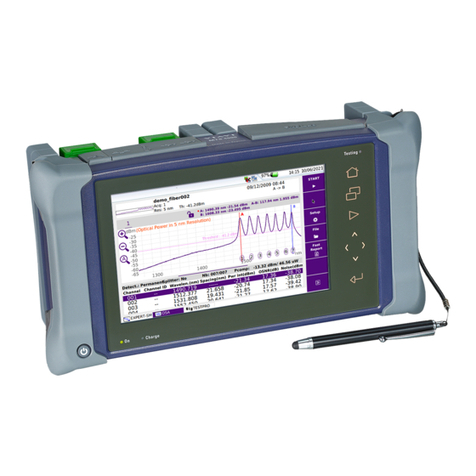
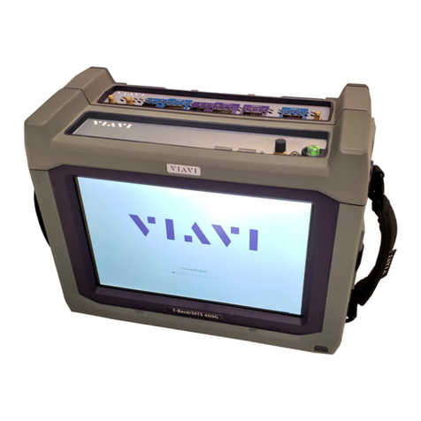
Follow this procedure to set up a T-BERD 5800 to run the Optical Time Domain Reflectometer
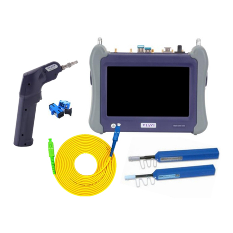
(OTDR). The picture below is of a TBERD 5800v2 with a Single Mode OTDR module attached. The
post of the OTDR module is covered with a green dust protector indicating that an Angled Physical
Contact (APC) connector is used on the port.
USEFUL INFORMATION: It is important to know the fiber distance from the BBU connection to the
RRU connection. This is typically the length of the hybrid plus any jumpers. These parts are typically
purchased at some standard length. When you run the OTDR test, you want to see the Test Set declare
“End of Fiber” at a distance that correlates to the “as built” information for the system under test. A
declaration of “End of Fiber” before that length indicates a connection is still open or there is a fiber
break.
1.1 Test Setup
Step Action Details
1. Power On Press and hold the ON/OFF button to turn on the T-BERD 5800v2.
2. Select Test Select the Fiber Optics Tab at the top of the screen
