Revision 9.0
February 2012
4Technical Assistance: 1-866-228-3762 TAC@jdsu.com
© 2012 JDSU. All rights reserved.
VDSL2 QUICK CARD
Resistive Fault Location (RFL) Test
Two Methods for Performing an RFL Test
RFL Test Single Pair Method (CAT 500 H/W)
Single pair testing should be used only if the separate pair method is not an option. is situation occurs when
there is no known good pair and if only one side (lead) of the pair under test is faulted. To perform single pair
RFL testing, the technician straps the good wire in the pair under test to the faulted (bad) wire. It is impor-
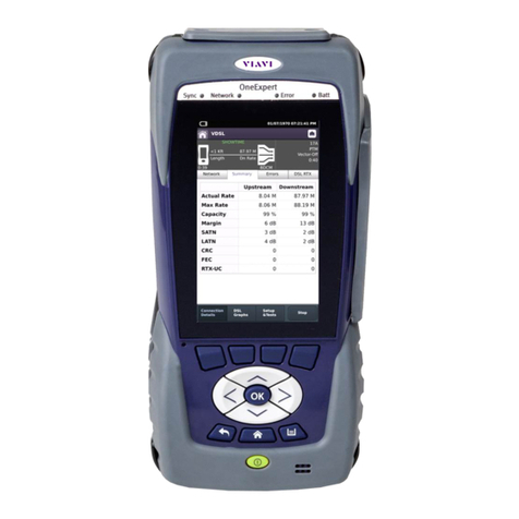
tant to note that RFL testing takes approximately 30 to 40 seconds. Arrows indicating the paths that are being
tested will be displayed on the HST-3000’s screen. Once the test is completed, each result will be shown in
either ohms or feet.
Temperature and Gauge: e temperature and gauge of the wires must be entered into the HST-3000 before
an accurate distance conversion can be performed.
Temperature: As the wires’ temperature changes, so does their resistance. For example, the higher the temper-
ature is, the greater the resistance. Because RFL determines the location of the fault through a series of resis-
tance measurements, the accuracy of the distance conversion is skewed in proportion to the dierence between
the temperature setting and the actual temperature.
Gauge: Gauge aects distance conversion because dierent gauge wires have dierent levels of resistance. (See
Table 5 below.) e higher the gauge is; the greater the resistance.
Measurement Pass
19 gauge/.8mm 16.09 Ohms/1000 feet (305m)
22 gauge/.6mm 32.4 Ohms/1000 feet (305m)
24 gauge/.4mm 51.32 Ohms/1000 feet (305m)
26 gauge/.4mm 82.01 Ohms/1000 feet (305m)
NOTE1: Typical ohms-per-feet/meter values
Table: 5 - Preferred and Non-Preferred Fault-Finding with a TDR
