Vibra AF-220 User manual

110001M31
High-Precision Analytical Electronic
Balance
AF Series
Operation Manual
SHINKO DENSHI CO., LTD.
To ensure safe and proper use of the balance, please read this
manual carefully.
After reading this manual, store it in a safe place near the
balance, so you can review it as needed.
IMPORTANT

2
PREFACE
Thank you for purchasing an AF Series electronic balance.
This balance can automatically be calibrated (span adjustment) at any time by a simple keystroke.
The balance is provided with a function for displaying the right timing for performing calibration
under various environmental conditions. This function enables the user to calibrate the balance as
required by the usage situation.
Furthermore, the balance comes standard with an output function that complies with ISO/GLP/GMP,
calendar and clock function, and applied measurement functions, including the piece-count,
percentage, and addition modes.
Meanwhile, this balance provides excellent usability represented by such facilities as a windshield
that allows the user to open/close the desired door, an easy-to-clean measuring chamber with
removable windshield doors and floor plate.
Contents of package
Take the balance and accessories out of the shipping carton carefully, and make sure that all of the
following items are included in the package.
(1) Main unit of balance (2) Operation manual (One)
High-Precision Analytical Electonic
Balance
AF Series
Operation Manual
Shinko Denshi Co.,Ltd
(3) AC adapter (One) (4) Measurement pan (One) •Pan base (One)
(5) DIN8P plug set
(For output to peripherals)
•Windshield ring (One)

1
CONTENTS
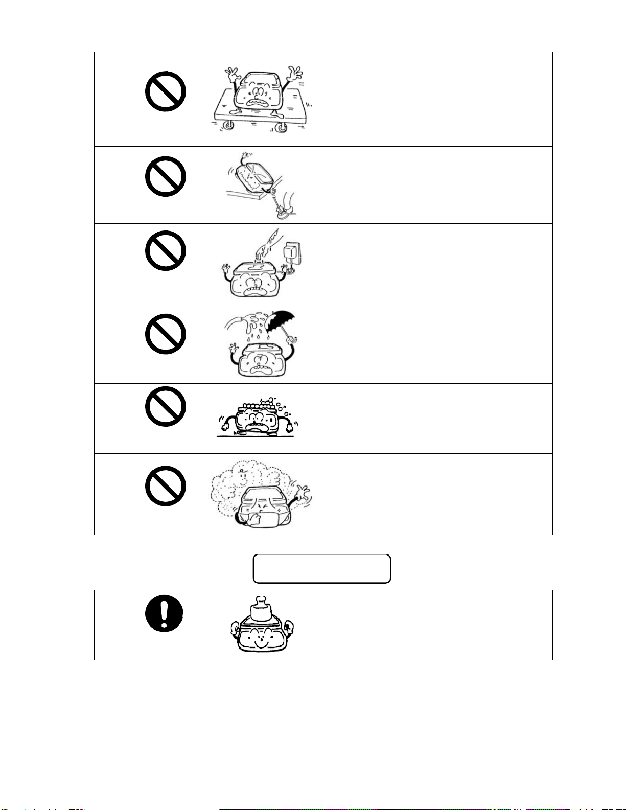
1. Precautions Relating on the Use........2
2. Specifications .....................................5
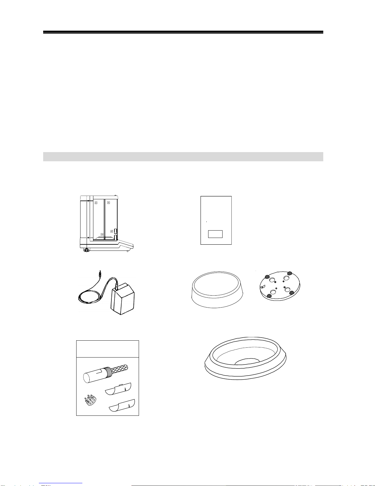
3. Names of Component Parts...............6
4. Installation ..........................................9
5. Operation Check...............................12
6. Time and Date Setup........................13
6.1 Time Setup..............................13
6.2 Date Setup..............................14
7. Calibration of Balance ......................15
7.1 Advice CAL.............................15
7.2 Span Adjustment with Built-In
Weight (Auto-Span
Adjustment).............................15
7.3 Span Test with Built-In
Weight.....................................16
7.4 Span Adjustment with External
Weight.....................................17
7.5 Span Test with External
Weight.....................................18
8. Basic Operations of Balance............20
8.1 Operation for Tare Range .......20
8.2 Example ofApplication ...........20
8.3 Minimum Indication Switching
Function..................................21
8.4 Interval Function.....................23
8.5 Time Output Function .............24
8.6 Counting Mode .......................25
8.7 Percentage Mode....................27
8.8 Addition Mode.........................28
8.9 Density Mode..........................29
9. Functions of Function 1....................30
9.1 Description of Function 1........30
9.2 Functions in Density Mode .....31
9.3 Interfaces................................31
9.4 Description of Compliance with
ISO/GLP/GMP ........................32
9.5 Setup and Check of
Function 1...............................32
10. Functions of Function 2....................33
10.1 Description of Function 2........33
10.2 Setup of ID No. ......................33
10.3 Setup of Error of Weight in
Use..........................................34
10.4 Calibration of Built-in Weight...36
10.5 Use of Weight Error ................37
11. Using the Printer...............................38
11.1 Setting up the Printer..............38
11.2 Printing in Compliance with
ISO/GLP/GMP ........................38
11.3 Recording Calibration
Results....................................38
11.4 Outputting Measurement Data
in Compliance with
ISO/GLP/GMP ........................39
12. Input/Output Functions.....................40
12.1 RS232C Output.......................40
12.2 Output to Peripherals..............43
12.3 Type of Communication
Texts........................................44
12.4 Output Data.............................44
12.5 Other Output Data...................46
12.6 Control with Commands..........47
13. Output in Compliance with
ISO/GLP/GMP..................................52
14. Servicing of Balance.........................58
15. Conversion Table of Units.................59
16. Troubleshooting................................60
Page Page

2
1. Precautions on the Use
This Section “Precautions Relating to Use” sets forth precautionary notes that the user should
observe in order to prevent physical injury to the user and/or damage to property.
The nature of problems that may result in the event of improper operation, and consequential
effects on the quality and performance of the balance, are indicated under the two categories of
“Caution” and “Recommended,” and explained using symbols.
注 意
!
CAUTION This symbol indicates a risk of injury or property damage if the
balance is used improperly. Be sure to observe these notes to
ensure safe use of the balance as the improper use may cause
serious results.
RECOMMENDED This term indicates steps that the user should take to ensure the
quality and reliability of the balance.
Meanings of Symbols Each symbol is accompanied by an instruction.
強制記号
Mandatory
Symbol:
Indicates a “mandatory” action that should be
executed without fail.
水平確認
Check Level
禁止記号
Prohibitive
Symbol:
Indicates a “prohibited” action that must not be
executed.
使用禁止
Do not Use
注 意
!
CAUTION
分解禁止
Do Not
Disassemble
Do not disassemble or modify the unit.
•Could cause malfunction or heat
generation
•Contact our Marketing Division or
Technical Service Division.
定格外禁止
Do Not Deviate
from Ratings
Only AC power (rated value) should be
used.
Only use the dedicated AC adapter.
•Use of other types of power or adapters
may result in heat generation or
malfunction of the balance.
移動禁止
Do Not Move
Do not move the balance when a sample is
loaded.
•The loaded sample may fall off the
measurement pan and cause an injury.

3
定格外禁止
Do Not Use
Do not place the balance on an unstable
base or use the balance in a location
where it may be subjected to shock.
•The loaded sample may fall off the
measurement pan.
•Accurate measurement may be rendered
impossible.
定格外禁止
Do Not Drop
Do not lay the AC adapter cable on the
surface of the passage.
•Somebody may trip on the cable, causing
the balance to fall off, thereby causing
injury and/or damage to the balance.
定格外禁止
Do not Handle
with Wet Hands
Do not touch the AC adapter or balance
with wet hands.
•Danger of electric shock
定格外禁止
Keep Dry
Do not use the balance in a location were it
may be subjected to excess moisture.
•Electric shock or short-circuiting could
occur.
•The balance may be corroded, with
resultant malfunction.
定格外禁止
Do Not Leave
Afloat
Do not use the balance with its adjusters
lifted.
•The balance will become unstable,
preventing accurate measurement.
定格外禁止
Avoid Dust
Do not use the balance in a location where
it may be subjected to excess dust.
•Risk of explosion or fire
•Short-circuit or lack of continuity may
occur, leading to a malfunction of the
balance.
RECOMMENDED
Calibrate
Balance
Calibrate the balance after installation or
relocation.
•Measurement values may contain errors,
preventing accurate measurement from
being conducted.

4
定格外禁止
Do Not Apply
Force
Avoid applying excess force or impact to
the balance.
•Place the sample to be measured on
the balance carefully to prevent
breakage or malfunction.
定格外禁止
Do Not Use
Do not use the balance in a location
were it may be subjected to abrupt
changes in ambient temperature or
humidity.
•Accurate measurement may not be
obtained.
•Use the balance in an ambient
temperature range from 10°C to 30°C.
定格外禁止
Do Not
Overload
Do not use the balance when [
] (Overloaded) is displayed.
•Take down the loaded sample
immediately to prevent breakage or
malfunction.
定格外禁止
Do Not Use
Do not use the balance in a location
where it is subject to direct sunlight.
•The indications would be illegible.
•An internal temperature increase in the
balance may lead to inaccurate
measurement.
Unplug
Adapter
If the balance is to be unused for an
extended period of time, unplug the
adapter.
•This conserves power and prevents
deterioration.
定格外禁止
Do Not Use
Do not use volatile solvents for cleaning.
•The body may be distorted.
•To clean the unit of stains, use a piece
of dry cloth or cloth soaked in a small
quantity of neutral detergent.
定格外禁止
Do Not Use
Do not use the balance in a location
where it may be subject to air from an
air-conditioning unit.
•Extreme changes in the ambient
temperature may result in inaccurate
measurements.
定格外禁止
Do Not Use
Do not use the balance on a soft floor.
•When loaded with a sample, the
balance may tip or move, preventing
accurate measurements from being
conducted.
Check Level
Do not use the balance when it is tilted.
•An inclined balance is likely to produce
errors, preventing accurate
measurements from being conducted.
Place the balance on a level surface.

5
2. Specifications
1. Common Specifications
1. Measurement system..................Electromagnetic force balancing system
2. Tare range ...................................Total capacity
3. Liquid-crystal display (LCD).........Indication in max. 8 digits (Weight indications produced
in 7 digits, in characters 18 mm high)
4. Calibration (Span Adjustment).....Span adjustment with built-in weight (Auto-span
adjustment)*
Span adjustment with external weight.
5. Measuring function......................Weight mode, counting mode, percentage mode,
addition mode, and density mode.
6. Various functions.........................ISO/GLP/GMP functions. (Compatible printer:CSP-160)
Calendar and clock function
7. Overload indication......................[
] is displayed if the weighing capacity + 9
graduations are exceeded.
8. Operating temperature and humidity ranges
.....................................................10°C to 30°C, 80%RH or less.
9. AC adapter ..................................Dedicated AC adapter: UM019 (9 VDC, 700 mA/120
VAC), or UM069 (9 VDC, 600 mA/230 VAC)
10. Output..........................................Bidirectional RS232C output
Output for peripherals
* Applies only to models with the built-in weight
2. Specifications by Model
Model AF-R220 AF-220
Capacity 220 g 220 g
Scale interval* 0.0001 g/0.0002 g/0.0005 g/0.001 g/0.002 g
Measurable unit weight 0.0001 g 0.0001 g
%-limit weight value 0.01 g 0.01 g
Size of measurement pan φ80 mm
Weight of main unit Approx. 5.5 kg Approx. 5 kg
Built-in weight Provided Not provided
* Changeable by switching Function 1

6
3. Names of Component Parts
3.1 Main Unit
The relevant reference pages are given in parentheses ( ) to the
right of (or under) the component names.
A
C adapter jack
(page 9)
D-SUB9P
RS232C output
connector (page 40)
DIN8P connector
Output for peripherals
(page 43)
A
djuster
Measurement pan
Windshield (pages 10, 58)
Knob (page 10)
Door storage cover (page 58)
W
indshield
ring
Hook for under-floo
r
measurement
(page 11)
Panel section
(page 7)
LCD (page 8)
Level (page 9)

7
3.2 Panel Section
No. Name Description
1 Zero/Tare key Operation key for zero-setting and tare range.
Selection key for choosing set values of various
functions.
2 On/Off key Key to turn on/off the unit power
3 Print key Key to start print or output
Key to cancel a time, date, or ID No. setting
4 Cal key Key to start span adjustment or span test
5 Set key Key to set various functions and to end the setup
Key to invoke the interval function
6 Function key Key to invoke various functions and to select items
7 Level
Used to check the level of the balance during
installation.
(The adjusters should be turned so that the bubble is
positioned in the center of the red circle.)
12 3
4
5
1
6
7

8
3.3 LCD Section
Σ
0
Display Description
mg Milligram
g Gram
ct Carat
mom Momme
oz Ounce
lb Pound
ozt Troy Ounce
dwt Pennyweight
GN Grain
tl (Top right) Tael (Hong Kong)
tl (Center right) Tael (Singapore、Malaysia)
tl (Bottom right) Tael (Taiwan)
tl (Top right)
(Center right) Tola
NET ΣAddition mode
PCS Counting mode
% Percentage mode
Data output
M Display of set values from memory (If a value is flashing, it is
being saved.)
○Indication of stable balance (If this light is off, the balance is
unstable.)
→0←Zero point
→T←Tare being subtracted
CAL Stays on and flashes while span adjustment, span test, or
calibration of the built-in weight is in progress. Flashes during
Advice CAL operation.
Stays on while the time and date are displayed, or flashes while
an interval output is in progress.
*Balance powered up (Lights up when the power is turned off).
(Top left) Lights up when an ID No. is indicated.
Lights up when an interval output time is displayed or set.
(Center left) Lights up when a weight error is displayed
Bar graph (Visual presentation of the range represented by the
weight of the sample within the capacity)

9
4. Installation
4.1 Main Unit
(1) Installs the windshield ring, pan base, and the measurement pan on the main unit, in that order.
Clean these components before installation.
(2) Place the balance at a specified level. Turn the adjusters to bring the bubble of the level to the
center of the red circle.
Correct Position of the Level Bubble
(3) Connect the AC adapter to the balance and plug the other end into a power outlet.

10
4.2 Windshield
The right and left doors can be opened/closed freely when the upper and lower knobs on both
sides of the windshield are properly combined. There are two types of knobs: a knob (upper)
fixed to the door and a knob (lower) that simultaneously slides right and left. When the knob
(lower) is raised or lowered so as to be locked into or unlocked from the knob (upper), the
windshield can manipulated freely, depending on whether the user is right-handed or left-handed,
how the sample is to be loaded on the measurement pan, etc.
Moreover, the right and left doors can easily be removed for cleaning of the interior of the
measurement chamber.
1. Opening/closing of windshield doors
To handle the windshield doors with the alternative hand while one hand is used to load/unload
samples:
Push up the knob (lower) on the side where samples are to be loaded/unloaded, and lock it into the
knob (upper). On the other side, push down the knob (lower) to free it. In this way, the windshield
on the loading/unloading side can be opened/closed with the knob of the other side*1.
Knob (Upper)
Knob (Lower)
Example: To load/unload a sample with the right hand and to open/close the right-hand door with
the left hand:
(1) Right-hand side
Locked Push up the knob (lower) to lock it into the knob (upper).
(2) Left-hand side
Unlocked Push down the knob (lower) to unlock it.
In this way, the door on the right-hand side can be opened/closed with the knob on the left-hand
side. The doors are opened/closed with the knob (lower).
*1 To open/close the right and left doors independently, push down both knobs (lower) to unlock
them. In this case, the doors are opened/closed with the knobs (upper).

11
4.3 Under-floor Measurement
This balance is provided with a hook designed for under-floor measurement. This lets you conduct
measurement with a lower pan or other device suspended from the hook. In case a sample does
not allow accurate measurement when placed on the measurement pan, such as in the presence
of a magnetic material or strong static electricity, use the following under-floor measurement
procedure.
(1) First, unplug the AC adapter. Fully open all windshield
doors and remove the measurement pan, pan base,
windshield ring, and floor plate. To detach the floor plate,
hold it by the sides with both hands and pull it up.
(2) Turn the balance down and lay it on its back.
Hook cover
(3) Loosen the screw of the hook cover and rotate the hook
cover 90 degrees around the screw.
(4) Retighten the screw.
Rotate the
cover around
the screw.
Screw
(5) Put the floor plate, windshield ring, pan base, and
measurement pan back in place, and close all the
windshield doors.
The balance is now ready for under-floor measurement. Hook for unde
r
-floor
measurement
Cautions:
1. Since the device suspended (lower pan) from the hook is treated as a tare, measurement
equivalent to the full weighing capacity cannot be conducted. The measurable weight will
be as follows:
Measurable Weight = Weighing Capacity - Weight of Suspended Device
2. If you are not going to conduct under-floor measurement any soon, keep the hook cover
closed to minimize dust.

12
5. Operation Check
5.1 Start
Σ
0
Press the On/Off key. All the indications start
flashing. Check the indications to ensure that no
indication is missing or unlit.
Only the [M] mark will flash for several seconds, and the
balance will change to measurement mode.
M
↓
○
g
5.2 Operation Check
Push the measurement pan lightly by hand and make
certain that the weight indication does vary and that it
returns to the original indication after you release your
hand. (If the zero-point is deviated, press the
Zero/Tare key to adjust the zero-point.)
○
g
↓
g
↓
○
g
* For the balance to perform stable measurement, start measurement after 30 minutes has
elapsed (warming-up) following the power-up. During this process, leave the right and left doors
open halfway to allow the interior of the windshield to be acclimatized to the external air
temperature. A temperature difference between the inside and the outside of the windshield
may give rise to convection when the doors are opened/closed, thereby preventing accurate
measurements from being conducted.

13
6. Time and Date Setup
The time, date and ID No. (see “10.2 Setup of ID No.” on page 33) are used when printing is made
in compliance with ISO/GLP/GMP. When this data needs to be printed, make the necessary
settings or verify the current settings.
6.1 Time Setup
While the time is displayed, --- stays on. The time is displayed in 24-hour mode [Hour: Minute:
Second]. Do not set any unreal time.
1. Time display and setup
(1) Press and hold down the Function key for several
seconds. Release the key when the display changes
from [] to [].
(2) Press the Function key again. The display
automatically changes to indicate time after briefly
showing [].
To go back to measurement mode without setting the
time, press the Print key.
Continuous
press
(1)
(2)
○
g
↓
↓
(3) Press the Set key to setup/change the time. First,
the leftmost position flashes, indicating the digit that
can be altered.
(4) Change the flashing digit by pressing the
Zero/Tare key.
(3)
↓
::
(5) Press the Function key. Pressing the key once
moves the cursor one step to the right. If the cursor is
at the final digit, it will return to leftmost position when
the key is pressed.
(4)
/
::
::
(6) Save the set value by pressing the Set key*1. This
saves the changes and brings up the date display
screen.
(5)
(6)
::
::
*1 Pressing the Print key restores the original time
display.

14
2. ±30-sec adjustment function
The ±30-sec adjustment function serves to make fine adjustment to the internal clock. Namely,
when the current time display shows less than 30 seconds, this function discards the seconds and
advances the time by one full minute.
(1) Display the time. (See (1) and (2) in 1. Time display
and setup.)
(2) Press the Zero/Tare key.
(3) Press the Print key to return to measurement
mode.
/
::
↓
::
6.2 Date Setup
When the display shows the date, · comes on. The year is represented by the last 2 digits. The
display order can be altered using Function 1. (See “9. Functions of Function 1” on page 31.)
(1)
(2)
○
g
↓
↓
Do not set any unreal date.
(1) Press and hold down the Function key for several
seconds. Release the key when the display changes
from [] to [].
(2) Press the Function key twice. The display shows
[] for 2 seconds and automatically changes
to indicate the date.
To return to measurement mode without setting a
date, press the Print key.
(3) Press the Set key. The leftmost position starts
flashing. The cursor denotes the digit that can be
altered.
(3)
↓
(4)
/
(4) Press the Zero/Tare key. Each press rotates the
digit.
(5) Press the Function key. Each press moves the
cursor to the right. If the cursor is at the final digit, it
will return to leftmost position when the key is
pressed
(6) Press the Set key. This saves the changes you
have made, and returns you to measurement mode*1.
(5)
(6)
*1 Pressing the Print key restores the original date
display.
○
g

15
7. Calibration of Balance
7.1 Advice CAL
To ensure conduct accurate measurement under varying environmental conditions, it is essential to
calibrate the balance (span adjustment). “Advice CAL” denotes the function that indicates the
suggested timing of calibration (span adjustment) by causing the [CAL] mark to flash. If the [CAL]
mark starts flashing, execute calibration (span adjustment) of the balance as soon as possible.
(1) Display [ ] by using “9. Functions of Function 1” (page 30) as the guide.
(2) Set the rightmost digit to []*1 by pressing the Zero/Tare key.
(3) Press the Set key to go back to measurement mode.
*1 To deactivate the function, display [ ].
7.2 Span Adjustment with Built-in Weight (Auto-Span Adjustment)
This function enables the user to practice the span adjustment automatically by simply pressing
the Cal key. This function is effective when the function is set to Span Adjustment with Built-in
Weight (Auto-Span Adjustment) [ ]. (See “9. Functions of Function 1” on page 30.)
While the span adjustment is in progress, a [CAL] mark will flash.
* This function is not available on models without the built-in weight.
(1) Start of span adjustment
Make sure that there is nothing loaded on the
measurement pan, and that the windshield doors are
completely closed. Then, press the Cal key. The
balance displays [ ] and, then, initiates the
span adjustment.
○
g
CAL
(2) Setup of zero-point
The display begins to flash [ ], and the balance
automatically sets a zero-point.
CAL
(3) Setup of weighing capacity point
When the zero-point setup is over, the balance now
displays [ ]. Several seconds later, the display
begins to flash and the balance automatically sets a
weighing capacity point.
CAL

16
(4) End of span adjustment
When the setup of a weighing capacity point is over,
the balance displays [ ], and returns you to
measurement mode.
CAL
○
g
Cautions:
1. While the adjustment is in progress, do not touch the measurement pan and protect the
balance from shock or movement. If the balance is moved, the processing may be halted at
the stage of the flashing [ ].
2. To cancel the adjustment midway, press the Print key. The balance returns to
measurement mode after briefly displaying [].
3. Avoid conducting the span adjustment immediately after the balance has been powered up.
Always wait for at least 30 minutes before conducting the adjustment.
7.3 Span Test with Built-In Weight
This function enables the user to conduct the span test automatically by simply pressing the
Cal key. Conduct this test after setting the function to Span Test with Built-In Weight
[ ]. (See “9. Functions of Function 1” on page 30.) While the span test is in progress, a
[CAL] mark will flash.
* This function is not available on models without the built-in weight.
(1) Start of span test
Make sure that there is nothing loaded on the
measurement pan and that the windshield doors are
completely closed. Press the Cal key. The
balance displays [ ] and initiates the span
test.
○
g
CAL
(2) Setup of zero-point
The display begins to a flash [ ], and the
balance automatically checks the zero-point.
(3) Check of weighing capacity point
When the zero-point check is over, the balance now
displays [ ]. Several seconds later, the
display flashes and the balance automatically checks
the weighing capacity point.
CAL
CAL
CAL
↓
(4) Display of span test result
When the weighing capacity point check is
completed, the balance displays [] and then
the result (error) of the span test in a weight value.
CAL
g

17
(5) End of span test
After the balance finishes displaying the span test
result, it displays [ ] and returns to
measurement mode.
CAL
○
g
Cautions:
1. While the adjustment is in progress, do not touch the measurement pan and protect the
balance from shock or movement. If the balance is moved, the processing may be halted at
the stage of the flashing [ ].
2. To cancel the adjustment, press the Print key. The balance returns to measurement
mode after briefly displaying [].
3. Avoid conducting the span test immediately after powering up the balance. Always wait for
at least 30 minutes before conducting the test.
7.4 Span Adjustment with External Weight
Conduct this adjustment after setting the function to Span Adjustment with External Weight
[ ]. (See “9. Functions of Function 1” on page 30.) While the span adjustment is in
progress, a flashing [CAL] mark will flash.
For this adjustment, prepare a weight*1 equivalent to the weighing capacity. Also, a more accurate
adjustment may be conducted when the instrumental error of the weight to be used is set. (See
“10.3 Setup of Instrumental Error of Weight in Use” on page 34 and “10.5 Use of Instrumental
Error” on page 37.)
(1) Start of span adjustment
Make sure that there is nothing loaded on the
measurement pan and that the windshield doors are
completely closed, then press the Cal key. The
balance displays [ ] and initiates the
span adjustment.
○
g
CAL
(2) Setup of zero-point
The display begins to flash [ ], and the
balance automatically checks the zero-point. If Setup
and Use of Instrumental Error was selected (see
pages 34 and 37), the balance displays the
instrumental error of the weight entered before the
zero-point setup.
mg
+
Displayed when “Use Instrumental
Error of Weight” is selected
CAL
(3) Setup of weighing capacity point
After the zero-point has been adjusted, the balance
displays [ ]. Load the span adjustment
weight*1 quietly on the measurement pan. The display
begins to flash, and the balance automatically sets a
capacity point.
Weight loaded
CAL
CAL

18
(4) End of span adjustment
When the adjustment of the capacity point is over,
the balance displays [ ] and ends the span
adjustment. Once you are back in measurement
mode, unload the span adjustment weight.
CAL
○
g
*1 Use a span adjustment weight of Class E2(or equivalent) or better under OIML Standard.
Cautions:
1. While the adjustment is in progress, do not touch the measurement pan and protect the
balance from shock or movement. If the balance is moved, the processing may be halted at
the stage of the flashing [ ] or [ ].
2. To cancel the adjustment, press the Print key. The balance returns to measurement
mode after briefly displaying [].
3. Avoid conducting the span adjustment immediately after the balance has been powered up.
Always wait for at least 30 minutes before conducting the adjustment.
7.5 Span Test with External Weight
Conduct this test after setting the function to Span Test with External Weight [ ]. (See
“9. Functions of Function 1” on page 30.) While the span test is in progress, a [CAL] mark will flash.
For the span test, use a weight*1 equivalent to the weighing capacity. Also, a more accurate
adjustment will be conducted when the error of the weight to be used is set. (See “10.3 Setup of
Error of Weight in Use” on page 34 and “10.5 Use of Weight Errors” on page 37.)
(1) Start of span test
Make sure that there is nothing loaded on the
measurement pan and that the windshield doors are
completely closed, then press the Cal key. The
balance displays [ ] and initiates the span
test.
○
g
CAL
(2) Check of zero-point
The display begins to flash [ ], and the
balance automatically checks the zero-point. If
Setup and Use of Instrumental Error was selected
(see pages 34 and 37), the balance displays the
instrumental error of the weight entered before the
zero-point setup.
mg
+
CAL
This manual suits for next models
1
Table of contents
Other Vibra Scale manuals

Vibra
Vibra VIBRA HAW 3 User manual

Vibra
Vibra AJH Series User manual

Vibra
Vibra SJ-E Series User manual

Vibra
Vibra SA/CA Series User manual

Vibra
Vibra AJ220NT/DBNT User manual

Vibra
Vibra HJ-KE Series User manual

Vibra
Vibra AJ Series User manual

Vibra
Vibra GZII-CEx Series User manual

Vibra
Vibra HJ-K Series User manual

Vibra
Vibra FZ623E Series User manual

Vibra
Vibra CG-K User manual

Vibra
Vibra AJ-CESeries User manual

Vibra
Vibra DJ-150E User manual

Vibra
Vibra CUX Series User manual

Vibra
Vibra CJ series User manual

Vibra
Vibra SJ-CE series User manual

Vibra
Vibra DJ series User manual

Vibra
Vibra AJ-E Series User manual

Vibra
Vibra SJ-6200 CE User manual

Vibra
Vibra ALE-NC Series User manual