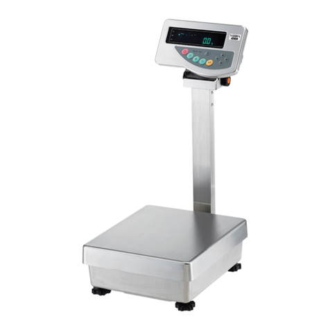
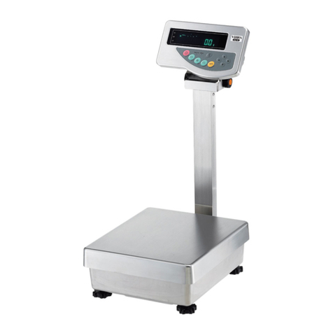
Vibra FZ623E Series User manual

410021M61
Intrinsically Safe Explosion-Proof
High-Precision Tuning Fork Scale
FZ623Ex/FZ3202Ex/
FZ6202Ex/FZ15001Ex
Installation Manual
SHINKO DENSHI CO., LTD.
IMPORTANT
•
To ensure safe and proper use of the scale, please read this
manual carefully.
•After reading this manual, store it in a safe place near the scale,
so you can review it as needed.

はくし

- i -
Preface
Thank you very much for having purchased a dust- and water-proof intrinsic safety
explosion-proof structure electronic scale, FZ623Ex, FZ3202Ex, FZ6202Ex and FZ15001Ex.
This document describes important items to use the device safely in the explosive atmosphere.
Read this document carefully before use to correctly operate.
■
About the certified explosion-proof structure
This scale is an explosion-proof electronic scale that has been certified as an intrinsic
safety explosion-proof structure electric device. It has been confirmed that the device does
not explode due to the generation of electric sparks or temperature rise of a component not
only during normal operation but also during abnormal operation (failure period) even when
used in the atmosphere of explosive gas.
Explosion-proof structure that has been certified
■About the dust- and water-proof structure
This scale is an electric device equipped with a dust- and water-proof structure.
(IPX5 is maintained when this scale is mounted in accordance with this manual.)
Protection class of a dust- and water-proof structure

- ii -
IECEx CERTIFICATE/Korean Certificate Safety
1
Certificate No. IECEx DEK 15.0059X/16-KA4BO-0469X
2
Type of Protection
ia
3
Marking Ex ia IIB T4 Ga/Ex ia IIB T4
4
STANDARDS
IEC 60079-0:2017 Edition 7.0 (IECEx DEK 15.0059X)
IEC 60079-0:2011 Edition 6.0 (16-KA4BO-0469X)
IEC 60079-11:2011 Edition 6.0
5
POWER SUPPLY
Maximum values
Ui Ii Pi Ci Li
20[V] 139[mA]
0.46[W]
0.21[μF]
0[mH]
6
S/N XXYYYY where XX is last two digits of the year of manufacture.
7
Symbol “X”: The insulation between an intrinsically safe circuit and the
frame of the (electrical) apparatus is not guaranteed.
Avoid excess voltage. From the safety point of view, the
circuit is considered to be connected to earth.
See 1-5-6 Grounding.
EU-TYPE EXAMINATION CERTIFICATE
1
Certificate No. DEKRA 15ATEX0072X
2
Marking II 1G Ex ia IIB T4 Ga
3
STANDARDS EN 60079-0:2018
EN 60079-11:2012
4
POWER SUPPLY
Maximum values
Ui Ii Pi Ci Li
20[V] 139[mA]
0.46[W]
0.21[μF]
0[mH]
5
Symbol “X”:
The insulation between an intrinsically safe circuit and the
frame of the (electrical) apparatus is not guaranteed.
Avoid excess voltage. From the safety point of view, the
circuit is considered to be connected to earth.
See 1-5-6 Grounding.

- iii -
Instructions
●The copyright of this document belongs to SHINKO DENSHI CO., LTD. Reprinting or
duplicating of all or part of this document without notice shall not be allowed.
●Please note that product improvement or modification may cause partial discrepancy
between the product and the description of this document.
●The description of this document is subject to change without notice.
●This document has been created carefully. If, however, any error or imperfection is found
by any chance, please let us know.
●Documents of which pages are missing or irregularly bound will be exchanged. Please
inform the store where you purchased the product or our sales department.
●Trouble related to the product or system will be dealt with in accordance with the
individual maintenance contract. Please note, however, that we will not take
responsibility for consequential trouble such as discontinuation of operation caused by
the product trouble.
●is the registered trademark of SHINKO DENSHI CO., LTD. Company names
and product names appearing in this document are the trademarks or registered
trademarks of the respective company concerned.

- iv -
Important Notice
・It should be known that this product contains potential danger. And so
please be sure to observe this document when installing, operating or
servicing this product.
・SHINKO DENSHI CO., LTD. will not take any responsibility for any injury
or damage caused by the non-observance of this document or misuse or
unauthorised modification of this product.
●
Potential dangers are increasing in the industrial equipment industries due to the
advent of new materials and processing methods, and speeding up of machines. It
is impossible to foresee all situations related to these dangers. In addition, there
are so many “impossible” and “don’ts” and so writing all of them in the operation
manual is impossible. Therefore, it is safe to think that what is not written in the
operation manual “cannot be performed” unless the operation manual positively
writes “it is possible.” When performing installation, operation, maintenance or
inspection of this product, not only observe what is written or indicated in this
document or on the product surface but also pay adequate consideration to safety
measures.
●
The copyright of this document is held and reserved by SHINKO DENSHI CO.,
LTD. Duplicating or disclosing its drawings and engineering materials without prior
approval of SHINKO DENSHI CO., LTD. in writing is not permitted.
●
For any question or further information concerning this document, please contact
the store where you purchased the product or with its model (type) name and serial
number informed.
●
Manufacturer: SHINKO DENSHI CO., LTD.
Address: 1-52-1 Itabashi, Itabashi-ku, Tokyo 173-0004 JAPAN

- v -
How to use this document
■Symbols used in this document
Understand the meaning of the following symbols and observe the instructions of this document.
Symbols Meaning
Used for high-risk point concerning the operations that may lead to death or
severe physical injury to persons if proper precautions are not taken.
Used for warning concerning the operations that may lead to death or severe
physical injury to persons, if proper precautions are not taken.
Used for caution concerning operations that may lead to a light physical injury
to persons if proper precautions are not taken.
Used for notation concerning operations that may lead to damage of the
products/facilities/data if proper precautions are not taken.
Used for accurate weighing and appropriate usage of the equipment.
Used for reference information
Used for “Prohibition” items
Used for “Mandatory” items requiring positive action
Used for prohibition items to avoid “Electrical shock”.
This symbol indicates the operation/specification related to verified scale for
legal metrology purpose.

- vi -
■About this document
This document explains assembling, installation, dismantling, maintenance, overhaul and
repair of the power supply box, indicator section and weighing section of the FZ623Ex, FZ3202Ex,
FZ6202Ex and FZ15001Ex (hereinafter referred to as “this product” or “the product”).
For how to install the interface option of the power supply box, please refer to the each option’s
manual.
For how to operate the product, please refer to the “FZ-Ex Series Operation Manual”
■About how to read this document
This document consists of the following contents:
1. Prior to use Describes precautions, checking for articles contained in the
box, the name and function of each section and the
assembling and installation of the product. Before installing
and using the scale for the first time, be sure to read this
document.
2. Maintenance Describes how to maintain this product.
3. Repair Describes information on repair.
4. Taking out of service and
dismantling
Describes information on taking out of service and
dismantling.
Appendix Provides necessary informations such as the specifications of
this product.

- vii -
Contents
Preface .................................................................................................................................. i
IECEx CERTIFICATE/Korean Certificate Safety ................................................................. ii
EU-TYPE EXAMINATION CERTIFICATE............................................................................ ii
Important Notice.................................................................................................................. iv
How to use this document.................................................................................................... v
Contents ..............................................................................................................................vii
1 Prior to use.................................................................................................................... 1
1-1 Precautions ........................................................................................................................ 1
1-2 For more accurate measurement ..................................................................................... 4
1-2-1 Precautions related to measuring environment ................................................................ 4
1-2-2 Precautions related to measuring table ............................................................................ 5
1-2-3 Precautions related to a specimen ................................................................................... 5
1-2-4 Precautions related to the main unit of a scale ................................................................. 6
1-3 Check for the articles contained in the box....................................................................... 7
1-4 Name and function of each section .................................................................................. 8
1-5 Assembling and installation.............................................................................................. 9
1-5-1 How to mount the pole and the indicator ........................................................................ 11
1-5-2 Mounting of the pan base and the weighing pan ............................................................ 13
1-5-3 Mounting of the windshield (Option) ............................................................................... 14
1-5-4 Installation of the power supply box................................................................................ 15
1-5-5 Leveling .......................................................................................................................... 19
1-5-6 Grounding....................................................................................................................... 20
1-5-7 Connecting to main power supply and starting up .......................................................... 21
2 Maintenance ............................................................................................................... 22
2-1 Care and cleaning method ............................................................................................. 22
2-2 Care and cleaning method in the case of heavy soil ...................................................... 22
2-2-1 How to remove the side windshield (Square pan) .......................................................... 23
2-2-2 How to remove the side windshield (Round pan) ........................................................... 24
2-3 How to replace the fuse.................................................................................................. 26
2-4 Maintenance of earth connection ................................................................................... 26
2-5 Troubleshooting.............................................................................................................. 27
3 Repair ......................................................................................................................... 28
4 Taking out of service and dismantling......................................................................... 28
Appendix ............................................................................................................................ 29
Appendix 1 Specification .............................................................................................................. 29
Appendix 1-1 Metrological specification................................................................................... 29

- viii -
Appendix 1-2 Common specification........................................................................................ 29
Appendix 1-3 The combination of the interface option ............................................................. 30
Appendix 1-4 Outline drawing.................................................................................................. 31
(Memo)

- 1 -
1 Prior to use
1-1 Precautions
■No disassembling or modification.
Unless specifically stated in this document, disassembling or modification of this product,
mounting or removal of an undesignated component no longer maintains the function of the
safety structure or explosion-proof structure, leading to a serious accident or physical injury.
■
Battery replacement absolutely unaccep
table
.
Never replace the battery built in this product by any means. The function of the
explosion-proof structure will be no longer maintained, leading to a serious accident or
physical injury.
■Install the power supply box in “non dangerous location”.
Installing the power supply box in a dangerous place will cause trouble such as an explosion
or a fire.
■Connect the grounding terminal and cables properly.
Improper connection of the grounding terminal and cables will cause trouble such as an
explosion or a fire.
■Keep Scale cable and DC power supply cable away from electromagnetic
source.
It may generate dielectric EMF, which degrades the intrinsic safety explosion-proof property
of the product and may lead to an explosion.
■
Install
S
c
ale
cable
and
DC p
ower
suppl
y
cable
properly
so as to
prevent
dielectric EMF.
Improper installation of them may impair the intrinsic safety performance of the product due
to the electrostatic induction, and electromagnetic induction and may lead to an explosion.
■Do not replace fuse, optional slots of the power supply box or access to
the AC power terminal when the AC power cord is connected to the mains
power.
That may cause an electric shock, short-circuiting or failure. Make sure disconnect from the
AC mains or shut down the AC mains before accessing to those parts.
■Do not connect the cables to the power supply box with its connector or
jack being wet.
That may cause an electric shock, short-circuiting or failure.
■Do not wet the power supply box or handle it with wet hands.
That may cause an electric shock, short-circuiting or failure.
■Do not open the AC connector cover unless the power supply box is
installed as a built-in unit on a distribution board or other enclosure of which
access is permitted to the trained and authorised persons only.
That may cause an electric shock, short-circuiting or failure.

- 2 -
■Do not move the device with a sample to be loaded on the scale.
That may cause the sample to fall from the weighing pan, leading to a physical injury or
destruction of the article.
■Do not use the product on an unstable table or a place that is subject to
vibration.
That may cause the article to fall from the weighing pan, leading to a physical injury or
destruction of the article. Besides inaccurate weighing may result.
■Do not place an unstable sample on the weighing pan.
The sample may fall down and cause injury. Put an unstable article in a container (tare)
before weighing it.
■Do not use the product with the enclosures, cables, connectors or any
external parts being damaged.
If those parts have damaged, be sure to disconnect the power supply box from mains power
supply, then ask the store where you purchased the product or our sales department for
repair. Keeping using the product may result in an explosion or fire. In addition, do not ever
try to repair it for yourself, or very dangerous situation is likely to occur.
■Do not use the product in an abnormal condition.
If it should happen that an abnormal event such as smoking or unusual odor occurs, be sure
to disconnect the power supply box from mains power supply, then ask the store where you
purchased the product for repair. Keeping using the product may result in an explosion or fire.
In addition, do not ever try to repair it for yourself, or very dangerous situation is likely to
occur.
■
Do not move the scale holding its
indicator, pole or
windshield.
That may cause base unit to fall, leading to a physical injury or malfunction of the scale itself.
Be sure to hold the base unit to move it.

- 3 -
Do not use the product where wind from an HVAC equipment directly
applies.
Accurate weighing may be impeded due to the fluctuation of surrounding temperature.
Do not use the product where there is direct sun.
Accurate weighing may be impeded due to the rise of internal temperature.
Do not use the product where floor is soft.
Accurate weighing may be impeded due to the tilting of the weighing section when an object
is placed on it.
Do not use the product where there is violent fluctuation of surrounding
temperature or humidity.
Accurate weighing may possibly be impeded. Use within a temperature range of 5 to 40 °C
and below a humidity of 85% RH.
■Do not connect the DC power supply cable, scale cable, or communication
cable to the scale with its connector or jack being wet.
That may cause short-circuiting or failure.
Do not give a shock to the scale.
It may cause breakage or
fa
il
ure. Pl
ace an
article t
o b
e
w
eighed softly.
Do not let an overload situation (o-Err indication) continue.
It may cause breakage or failure. Remove the article to be weighed immediately.
Do not use volatile solvent.
Use of volatile solvent is likely to deform the product. Dirt on the product should be removed
with a piece of dry cloth or cloth wet with small amount of neutral detergent.
Be sure to make adjustment at the time of installation or changing a use
place.
There occurs an error in measurement value. For the sake of accurate measurement, be
sure to make adjustment.
Check for an error periodically.
Use environment and chronological change cause an error in measured value, leading to an
inaccurate measurement.
Align the level of the scale without fail before use.
Weighing with a slanted scale causes an error, leading to an inaccurate measurement. Put
the scale on a robust place.

- 4 -
1-2 For more accurate measurement
To make more accurate measurement, it is necessary to lessen error-causing factors in
measurement to the extent possible. Error-causing factors include not only an instrument error
and performance of the scale itself but also the nature and condition of a specimen, measuring
environment (vibration, temperature, humidity, etc.) and the like. These factors will directly affect
measurement result in the case of a scale with high resolution capability.
1-2-1 Precautions related to measuring environment
Temperature/humidity
→Try to keep the room temperature constant to the extent possible in
order to avoid condensation and indication drift due to change in
temperature.
→Low humidity is likely to cause generation of static electricity,
resulting in inaccurate measurement.
Vibration/shaking →It is preferable to locate a measuring room on the first floor or the
basement. The higher the room is, the larger the vibration and
shaking become. Therefore a highly located room is not suitable for
measurement. Rooms near the railway or road side should also be
avoided.
Air draft →Places directly exposed to air current from an air-conditioner or to
direct sun generate abrupt temperature change and resultantly
cause unstable weight indication, and therefore, should be avoided.
Gravity →The latitude and altitude of a measuring location differentiate the
gravity that affects a specimen, giving a different weight indication
to the same specimen.
Electromagnetic
wave
→At a location where a strong electromagnetic wave generating
object is in the proximity of a scale, the scale is affected by the
electromagnetic wave, making the scale unable to indicate
accurate weight, and therefore, such a location should be avoided.

- 5 -
1-2-2 Precautions related to measuring table
Vibration/shaking →
Vibrations during measurement destabilizes the indication of
measurement value, leading to inability to make accurate
measurement. And so use of a measurement table that is robust
and hardly affected by vibration is required (a vibration-proof
structured table or concrete or stone-made table is suitable). In
addition, placing a sheet of soft cloth or paper under the scale
causes shaking or makes keeping horizontal attitude difficult, and
therefore should be avoided.
→The measurement table should be installed in a position free from
vibration to the extent possible. A corner rather than the center of a
room is less affected by vibration and therefore more suitable for
installation of the scale.
Magnetism/Static
electricity
→Use of the scale on the table that is subject to magnetism or static
electricity should be avoided.
1-2-3 Precautions related to a specimen
Static electricity →In general, synthetic resin- and glass-made specimens are high in
electric insulation, and so easily charged electrically. Weighing an
electrically charged specimen makes the indication value
unstable, reducing the reproducibility of the test result. Therefore,
neutralize an electrically charged specimen before measurement.
Magnetism →Specimens affected by magnetism show different weight in a
different position of the weighing pan, reducing the reproducibility.
When weighing a magnetized specimen, either eliminate the
magnetism from the specimen or place a setting plate on the
weighing pan to distance the specimen from the weighing
mechanism of the scale so that the mechanism may not be
affected by the magnetism.
Moisture
absorption/Evaporation
→Measuring a moist or evaporating (vaporizing) specimen
increases or decreases the indication value of the scale
continuously. When this is the case, put the specimen in a
container equipped with a small mouth and closely seal the mouth
before measurement.
Specimen temperature
→Difference in temperature between the specimen and the
windshield interior generates convection flow within the
windshield, causing a measurement error. When the specimen
temperature is excessively high or low, allow the specimen
temperature to stabilize at the room temperature before
measurement. Also, to prevent the convection flow from arising
within the windshield, make the windshield interior temperature
equal to the room temperature before measurement.
→Measurer’s body temperature also affects measurement result.
Handle a specimen with tweezers instead of directly holding it with
fingers and refrain from putting your hands directly in the
windshield during measuring operation.

- 6 -
1-2-4 Precautions related to the main unit of a scale
Operating
precautions
→For more stable measurement, it is recommended to energize the scale
for longer than 30 minutes and load the scale a few times with a weight
equivalent to the weighing capacity before measurement.
Adjustment →
Calibrate the scale periodically with an external adjustment weight.
For the sake of precise calibration, use an external adjustment weight
weighing nearly equal to the weighing capacity of the scale.
→
Energize the scale for longer than 30 minutes and load the scale a few
times with a weight equivalent to the weighing capacity before
measurement
→
Adjustment is also needed in the following cases:
When using the scale for the first time,
When using the scale after a long period of non-use,
When changing a place of installation, and
When there was a large change in temperature, humidity or atmospheric
pressure.
Maintenance →
Attachment of dirt such as powder or liquid to the weighing pan or pan
base will cause measurement error or unstable weight indication. For that
reason, frequent cleaning of the scale is required. In cleaning the scale,
take care for the dust or liquid not to enter into the scale (mechanism).

- 7 -
1-3 Check for the articles contained in the box
The package box contains the following;
If anything missing or broken should be found, please inform the store where you purchased the
product.
Part name Q’ty
Part name Q’ty
①
Indicator 1 ②
Base unit 1
each
③
Pole 1 ④
Pan base
(either a square or round pan) 1
⑤
Weighing pan
(either a square or round pan) 1 ⑥
Power supply box, AC power cord
1
⑦
DC Power supply cable 1 ⑧
Accessories

- 8 -
1-4 Name and function of each section
①
Indicator
②
Pole
③
Level
④
Weighing pan
⑤
Base unit
⑥
Adjuster
⑦
Intrinsic safety grounding terminal E (IS)
⑧
Enclosure grounding terminal
⑨
Scale cable
⑩
DC Power supply cable
①
DC power supply cable connecting terminal block
②
DC Power supply cable
③
RS232C connector (D-sub 9 pin male)
④
Power switch
⑤
Communication confirmation LED
⑥
Fuse holder (Fuse built-in)
⑦
AC connector cover
⑧
AC power cord

- 9 -
1-5 Assembling and installation
Don't connect the power supply box to the mains power supply until all the other
connections have been confirmed to be established correctly.
1
Installing condition
This product is a scale that can secure safety when in use even in an atmosphere of explosive gas.
However, wrong installation and handling give rise to a serious danger. For safe use, refer to
IEC/EN 60079-14 and IEC/EN 60079-25 to install the product properly and construct an
intrinsically safe electrical system.
・
DC power supply cable runs between dangerous section and non-dangerous section. Be
sure to conduct the specified gas flow prevention construction for the cable pull-in section.
・
Do not ever install the power supply box and the barrier in the dangerous section.
・
Separate DC power supply cable and scale cable adequately from electromagnetic
sources such as mortors or motor power cables. Otherwise, the intrinsic safety
performance may possibly be impaired due to the electrostatic induction and
electromagnetic induction. Perform the wiring with sufficient clearance dimension
provided.
・
Install Scale cable and DC power supply cable properly so as to prevent electrostatic
induction and electromagnetic induction. Do not roll them. Otherwise, the intrinsic safety
performance may possibly be impaired.
・A 5m long DC power supply cable is included as a standard accessory.
The DC power supply cable can be elongated in 5 m units on an option basis till 95m at a
maximum.
・Using other than Power supply box is not permitted for legal for trade purpose.

- 10 -
■System construction diagram
1. Insulation barrier, Indicator and Weighing Modules are to be consisted as shown in the figure above.
2. Supply circuit to the DC power supply cable (connector +DC, GND, TXD and RXD): in type of protection intrinsic safety Ex ia IIB, only for
connection to a certified intrinsically safe circuit, with the following maximum values:
Ui = 20 V, Ii = 139 mA, Pi = 0.46 W, Ci = 0.21 μF, Li = 0.
In addition to the above, the insulation barrier shall meet the following conditions:
- Certified product as [Ex ia Ga] IIB or higher grade
- Maximum load rating: Capacitance ≥1.41μF, Inductance ≥1.77 mH
* The barrier built into the power supply box meets the above conditions.
3. Conditions of the General Electric Apparatus:
The internal voltage of the device shall not be beyond 250 Vac, 50/60 Hz, 250Vdc
at either normal or the abnormal condition.
* The power supply box meets the above conditions.
4. The intrinsically safe apparatus, related equipments and connecting wires should be installed appropriately so as not to impair the explosion
proofness by electrostatic induction or electromagnetic induction.
This manual suits for next models
3
Table of contents
Other Vibra Scale manuals

Vibra
Vibra CJ series User manual

Vibra
Vibra HJ-K Series User manual

Vibra
Vibra VIBRA ALC 3 User manual

Vibra
Vibra AJ-E Series User manual

Vibra
Vibra HJ-KCE series User manual

Vibra
Vibra SA/CA Series User manual

Vibra
Vibra AJ Series User manual

Vibra
Vibra AF-220 User manual

Vibra
Vibra DJ series User manual

Vibra
Vibra AJH Series User manual

Vibra
Vibra GZ II Series User manual

Vibra
Vibra CG-K User manual

Vibra
Vibra SJ-E Series User manual

Vibra
Vibra AJ-CESeries User manual

Vibra
Vibra SJ-6200 CE User manual

Vibra
Vibra GZII-CEx Series User manual

Vibra
Vibra HJ-KE Series User manual

Vibra
Vibra CUX Series User manual

Vibra
Vibra AJ220NT/DBNT User manual

Vibra
Vibra TPS SERIES User manual