Vibra HJ-KCE series User manual

220011M01
High-Precision, Advanced Tuning Fork Balance
HJ-KCE/HJR-KCE Series
Operation Manual
SHINKO DENSHI CO., LTD.
●To ensure safe and proper use of the balance, please read this
manual carefully.
●
After reading this manual, store it in a safe place near the
balance, so you can review it as needed.
IMPORTANT

2
PREFACE
Thank you for purchasing an HJ-KCE/HJR-KCE Series electronic balance.
This balance is equipped with a high precision mechanism. It provides parts counting, percentage
weighing, and limit functions helpful in weighing a certain amount, and has various other functions.
This advanced balance employs a user-friendly program, and the key arrangement is also easy to
operate. In addition, the large fluorescent display is eye-friendly, and its high-speed, stable
performance improves your work efficiency.
Because all the models of the HJ-KCE/HJR-KCE series are dust- and water-proof (conforming to
IP65), they can be used in a place exposed to fine dust or to water jets. They can also be washed
in water when they are contaminated.
Check for the following accessories before use.
If you find missing or damaged parts, immediately contact the store where you bought the product
or our Marketing Division.
(1) Display (for the separate type or the pole type) (2) Cable cover
Balance
* The display and the balance are connected through a cable, and cannot be separated from each
other.
(3) Base cover (4) Connecting fitting (provided for the separate type)
(5) AC adapter (6) Operation manual

1
Contents
1 Precautions Relating to Use..........................2
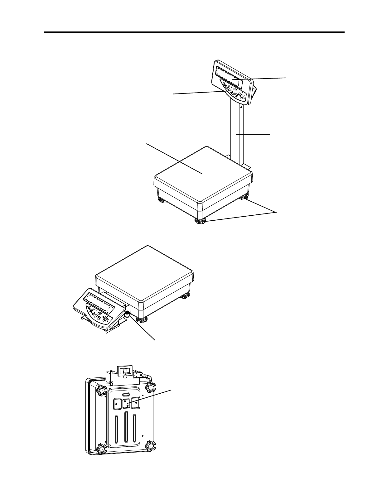
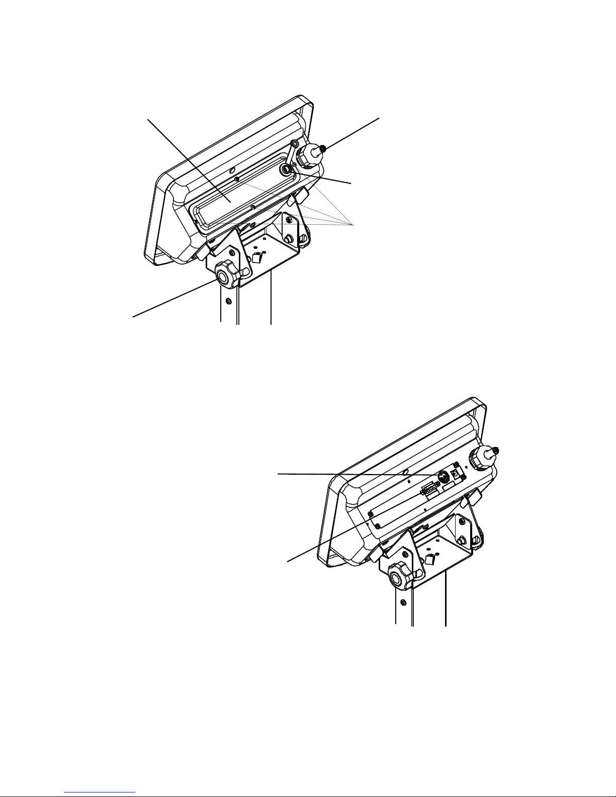
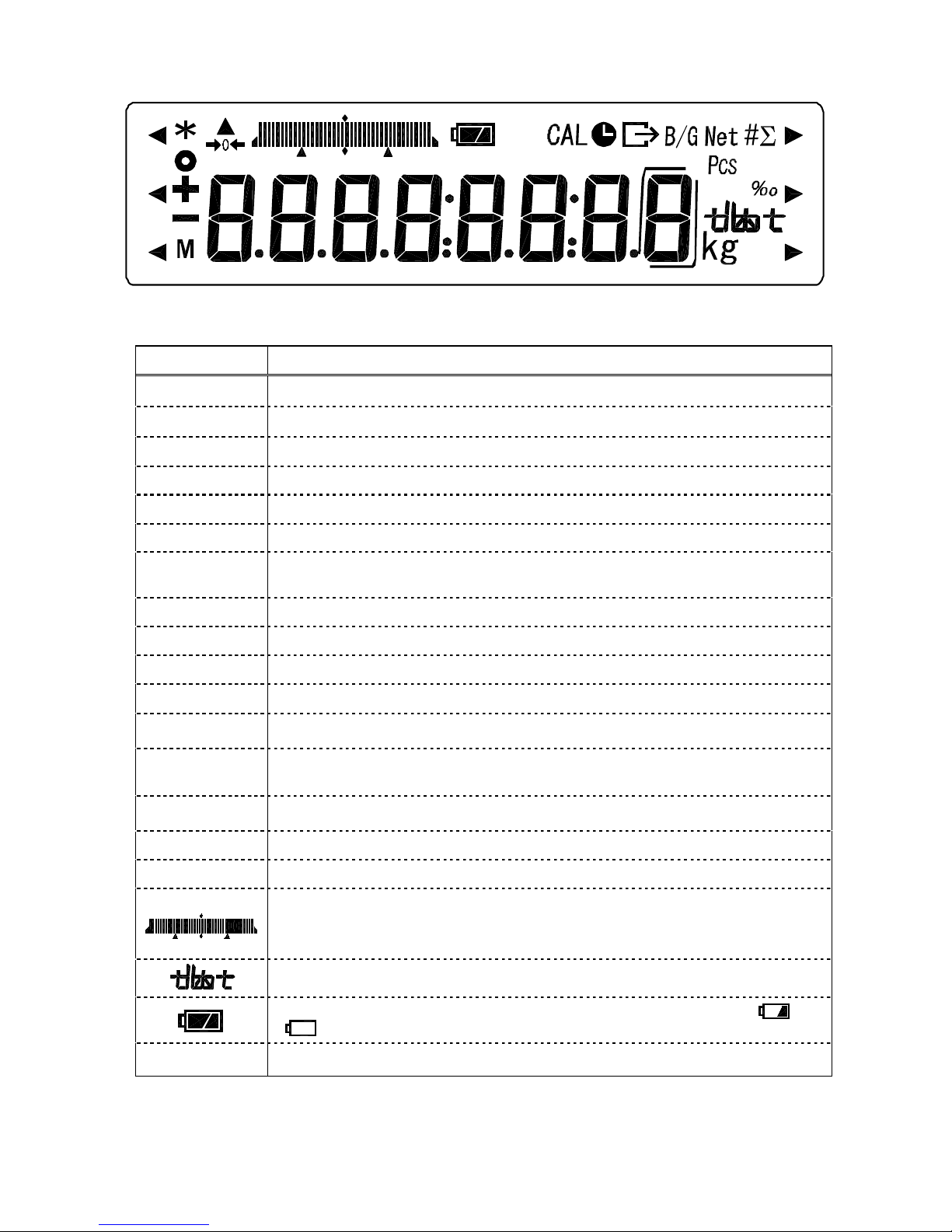
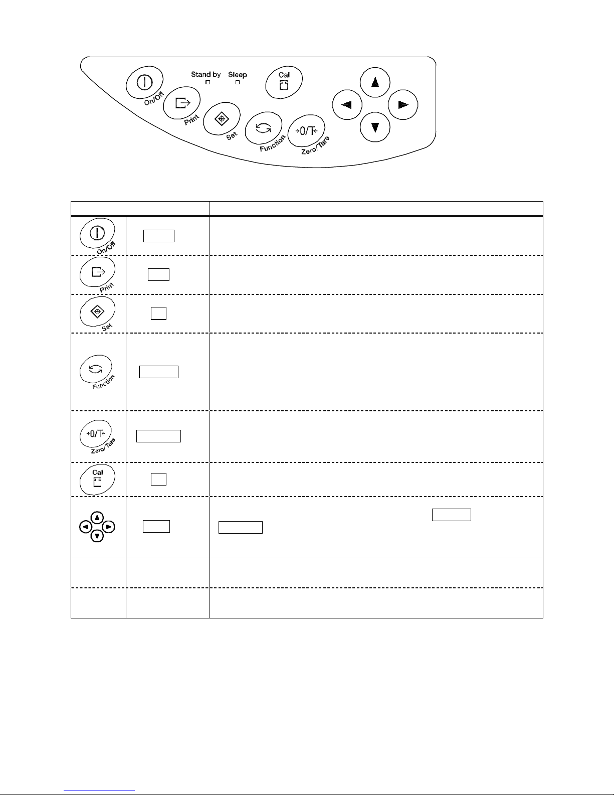
2 Names of Component Parts ..........................5
3 Installation of the Balance and Operation
Check
3.1 Installation.................................................9
3.2 Operation Check.................................... 11
4 Function 1
4.1 Setting and Check..................................15
4.2 Description of Function 1.......................16
4.3 Limit Function.........................................18
4.4 Interface..................................................19
5 Function 2.........................................................20
6 Weighing Mode
6.1 Measurement Modes.............................21
6.2 Weighing Machine..................................21
6.3 Parts Counting........................................22
6.4 Percentage Weighing.............................24
7 Accumulation function...................................26
8 Limit Function
8.1 Setting the Limit Function......................27
8.2 Judgment and Saving............................27
8.3 Display of Judgment Results.................27
8.4 Judge by Absolute Values......................28
8.5 Judge by Deviation Values.................... 30
8.6 Bar Graph for the 2-point Scale.............33
9 Calibrating the Balance
9.1 Span Adjustment with Built-in Weight... 34
9.2 Span Adjustment with External Weight.34
9.3 Span Test with Built-in Weight...............35
9.4 Span Test with External Weight.............35
9.5 Calibration of Built-in Weight.................36
10 Date and Time Setup.......................................37
11 Various Functions
11.1 Auto Sleep Function...............................38
11.2 Auto Power Off Function........................38
11.3 Set Unit Function....................................38
11.4 Double Range........................................39
11.5 Date Display...........................................39
11.6 Time Stamp Output ................................39
11.7 Direct Start Function...............................39
11.8 Interval Output Function........................40
11.9 Enter an ID Number...............................41
12.Input/Output Functions
12.1 RS232C Output......................................42
12.2 Output to Peripherals.............................45
12.3 Type of Communication Texts ...............46
12.4 Output Data............................................46
12.5 Input Commands....................................50
13 Use Printers......................................................55
14 Output in Compliance with
ISO/GLP/GMP...................................................56
15 Operate on Batteries.......................................59
16 Troubleshooting...............................................60
17 Specifications...................................................62
18 Conversion Table of Units..............................64

2
1 Precautions Relating to Use
This Section “Precautions Relating to Use” sets forth precautionary notes that the user should
observe in order to prevent physical injury to the user and/or damage to property.
The nature of problems that may result in the event of improper operation, and consequential
effects on the quality and performance of the balance, are indicated under the two categories
of “Caution” and “Recommended,” and explained using symbols.
This is a category to indicate improper handling that may
cause physical injury or severe damage to property. Be sure
to follow the directions for safe use to avoid serious
consequences.
This term indicates steps that the user should take to ensure
the quality and reliability of the balance.
Meanings of Symbols Each symbol is accompanied by an instruction.
Do not disassemble or modify the unit.
· Could cause malfunction or heat generation
· Contact our Marketing Division or Technical Service
Division.
Only AC power (rated value) should be used.
Only use the dedicated AC adapter.
· Use of other types of power or adapters may result
in heat generation or malfunction of the balance.
Do not move the balance when a sample is
loaded.
· The loaded sample may fall off the measurement
pan and cause an injury.
Recommended
Mandatory Symbol
: Indicates a “mandatory” action that should
be executed without fail.
Check Level
Example
:
Indicates a “prohibited” action that must not
be executed.
Example
!
Caution
Do Not
Disassemble
Prohibitive Symbol Do Not Use
Do Not Move
Do Not Deviate
from Ratings
!
Caution

3
Do not place the balance on an unstable base
or use the balance in a location where it may be
subjected to shock.
· The loaded sample may fall off the measurement
pan.
· Accurate measurement may be rendered
impossible.
Do not lay the AC adapter cable on the surface
of the passage.
· Somebody may trip on the cable, causing the
balance to fall off, thereby causing injury and/or
damage to the balance.
Do not use the balance with its adjusters lifted.
· The balance will become unstable, preventing
accurate measurement.
Do not submerge the balance.
· Although the balance is dust- and water-proof, it
cannot withstand high water pressure due to
submergence under water.
Calibrate the balance after installation or
relocation.
· Measurement values may contain errors,
preventing accurate measurement from being
conducted.
Do Not Use
Do Not Drop
Do Not Leave
Afloat
Do Not Submerge
Recommended
Calibrate Balance

4
Avoid applying excess force or impact to the
balance.
· Place the sample to be measured on the balance
carefully to prevent breakage or malfunction.
Do not use the balance in a location were it may
be subjected to abrupt changes in ambient
temperature or humidity.
· Accurate measurement may be rendered
impossible.
· Use the balance in an ambient temperature
between 5°C and 35°C and at a relative humidity of
80%RH or lower.
Do not leave the balance overloaded (When it is
overloaded, a series of dots () is
displayed).
· Take down the loaded sample immediately to
prevent breakage or malfunction.
Do not use the balance in a location where it is
subject to direct sunlight.
· The indications would be illegible.
· An internal temperature increase in the balance
may lead to inaccurate measurement.
If the balance is to be unused for an extended
period of time, unplug the adapter.
· This conserves power and prevents deterioration.
Do not use volatile solvents for cleaning.
· The body may be distorted.
· To clean the unit of stains, use a piece of dry cloth
or cloth soaked in a small quantity of neutral
detergent.
Do not use the balance in a location where it
may be subject to air from an air-conditioning
unit.
· Extreme changes in the ambient temperature may
result in inaccurate measurements.
Do not use the balance on a soft floor.
· When loaded with a sample, the balance may tip or
move, preventing accurate measurements from
being conducted.
Do not use the balance when it is tilted.
· When the balance is tilted, an error may be caused,
preventing accurate measurement from being
conducted. Place the balance on a level surface.
Do Not Apply Force
Do Not Use
Do Not Overload
Do Not Use
Do Not Use
Do Not Use
Do Not Use
アダプター
を抜く
Unplug Adapter
水平確認
Check Level

5
2 Names of Component Parts
2.1 Main Unit
2.1.1 Pole type (HJ[R]-KCE, HJ[R]-KDCE)
2.1.2 Separate type (HJ[R]-KSCE, HJ[R]-KDSCE)
2.1.3 Underside (common to the pole and separate types)
Display
Adjuster (4)
Pan Pole
Operation key
Level
Cover for openings for under weighing
(The hook for hanging is an option. For more
information, refer to the instruction manual for the
hook for hanging.)
*
Close the cover to protect against dust and water
when not in use.

6
2.2 Display (Backside)
* Common to the separate and pole types.
2.2.1 Backside
2.2.2 Output connectors (when the connector cover is removed)
To remove the connector cover, unfasten the four screws fixing the cover.
Caution:
When the connector cover is removed, protect them against water. The output connectors are
not dust- and water-proof.
When the buzzer output is installed, or the relay output or RS422A output is used, protect the
output connectors also against water as they are exposed.
Connector cover
Balance cable
Jack for the AC adapter
Knob
(Used to adjust the
angle of the display)
Screws to fix the connector cover
DIN8P connector for peripheral device output
D-SUB9P male connector for RS232C output

7
2.3 Displayed Signs and Operation Keys
2.3.1 Displayed signs
Display Description
kg Kilogram, gram
®0¬Zero point
-Minus
Net Tare sign
B/G Gross weight
Indicates stable balance (If this light is off, the balance is unstable.)
*Indicates that the accumulation function is enabled, and withstands additional
load.
Pcs Parts counting
% Percentage weighing
# Unit converting
SDisplays a sum total.
Displayed when data is output in compliance with ISO/GLP/GMP.
Lights up when outputs are accompanied by a date and time.
Blinks during interval output.
Displays a judgment by the limit function (HI/OK/LO).
M Displays set values from memory (If a value is flashing, it is being saved.)
CAL Lights up or blinks during span adjustment or when advice CAL is in operation.
· Bar graph
· Displays a judgment by the limit function (scale of 1 to 5)
(Refer to Hints on page 33).
Displays a set unit.
Battery indicator. As the battery gets weaker, the sign is changed into [ ] or
[ ]. (Refer to Section 15: Operate on Butteries on page 58).
Lights up only when the auxiliary scale interval is being displayed.

8
2.3.2 Operation keys and their functions
Operation key Function
On/Off keyTurns the balance on or off.
Print keyStarts output.
Also used to cancel the setting of a date and time.
Set key[Short press] Starts the setting of a count or a percent.
[Long press] Starts the setting of a limit value when the limit function is
enabled.
Function key
[Short press] Switches the measurement mode.
[Short press] Used to enter numerical values.
[Short press] Used to select a function to set.
[Long press] Calls functions.
Zero/Tare key[Short press] Sets a zero point or sets a tare weight.
[Short press] Used to enter numerical values.
[Short press] Used to select a function.
Cal keyStarts span adjustment or a span test.
Arrow keysThe arrow keys function in the same way as the Function key or the
Zero/Tare key when you set a function or enter numerical values for
additional functions.
LED
(green) Stand byLights up when the power is on (standby).
* The LED does not light up when the balance is operated on batteries.
LED
(orange)
SleepLights up when the auto sleep function is enabled.

9
3 Installation of the Balance and Operation Check
3.1 Installation
3.1.1 Procedure for installing the pole type balance
Lift the pan, and slide it backward.
Loosen the two knobs in the lower part of the pole.
Insert the pole into the balance so that the cable fits in the groove. Check that the supporting
boards are hooked on the bottom of the cable housing.
Fasten the two knobs in the lower part of the pole.
Fold extra cable and put it in the cable housing. Mount the cable cover vertically on the
housing with the both sides slightly opened.
Mount the base cover in the front of the cable housing so that it is hooked on the cable cover.
Put back the pan.
In order to level the balance, turn the adjusters so that the air bubble is centered in the viewer.
*
Numbers in the figure below correspond to the
above steps to install the balance.
Cross-section View of Pole Installation
Position of the air
bubble in the level
Pan Pole
Knob
Supporting
board
Cable housing
③
⑤
Cable housing
⑥
Knob
Adjuster
Supporting board
Base cover
Cable cover
Pole

10
3.1.2 Procedure for installing the separate type balance
To use the display and the balance separately from each other
Lift the pan, and slide it backward.
Slightly open both sides of the cable cover, and mount it vertically in the cable housing.
Mount the base cover in the front of the cable housing so that it is hooked on the cable cover.
Put back the pan.
In order to level the balance, turn the adjusters so that the air bubble is centered in the viewer.
To integrate the display with the balance
Lift the pan, and slide it backward.
Loosen the two knobs in the connecting fitting, and mount it vertically in the cable housing.
Check that the supporting boards are hooked on the bottom of the cable housing.
Fasten the two knobs in the connecting fitting.
Fold the cable and put it in the cable housing with 15 cm of the cable left unfolded in the
display end.
Slightly open both sides of the cable cover, and mount it vertically in the cable housing.
Insert the display in the connecting fitting at an angle.
Put back the pan.
Mount the base cover vertically.
In order to level the balance, turn the adjusters so that the air bubble is centered in the viewer.
* Numbers in the figure correspond to
the above steps to install the balance.
Position of the air
bubble in the level
AdjusterCable housing
Base cover
Cable cover
Cable cover
Display
Cross-section View of Connecting Fitting Installation
Base cover
Knob
Cable housing
Adjuster
(Connecting
fitting) Supporting board
Pan
Knob
Cable housing
Supporting board

11
3.2 Operation Check
3.2.1 Turn the power on and off and check the display
Connect the AC adapter.
The balance enters standby mode, and the Stand by
lamp (LED) lights up.
Press the On/Off key.
When the display lights up, check it for missing signs.
When an object is lying on thepan, theblinking “on 0”
is displayed. In such cases, remove all the objects on
the pan.
If a unit other than “g” (gram), “kg” (kilogram) or “ct”
(carat) is selected as Unit A, the unit automatically
changes to “g.”
Check changes of the display.
Give the pan a slight press, and check that the
display is changed.
Check that the display goes back to zero when you
lift your hand.
Stand by
Press the On/Off key again.
The balance enters standby mode, and the Stand by
lamp (LED) lights up.
3.2.2 Set a Tare Weight
1 Put tare (container) on the balance.
Put tare on the balance, and the weight is displayed.
2 Reset the display to 0.
Press the Zero/Tare key.
The tare weight is set, and the display is reset to
zero.
3 Put a sample on the balance.
The net weight of the sample in the container is
displayed.
→0←
g
g
→0← Net
g
g
Net
g

12
Weigh additional samples
4 Reset the display to 0.
Press the Zero/Tare key.
The gross weight of the sample on the pan is reset to
0.
5 Put an additional sample on the balance.
The weight of the additional sample is displayed.
In this way, you can add a sample and weigh it by
pressing the Zero/Tare key to reset the displayed
weight to 0.
3.2.2 Display a gross weight
This balance has a function to display a gross weight including a sample and tare. A sample weight
including tare is referred to as a gross weight, and a sample weight excluding tare is referred to as
a net weight. A gross weight can only be displayed when the balance is used as a weighing
machine.
Put tare on the balance to set the tare weight.
Put a sample to weigh on the balance.
The net weight of the sample is displayed.
Press the Function key one time.
The gross weight including the tare weight is
displayed.
The B/G sign is displayed.
When you press the Function key again, the balance
is reset to the normal mode.
Caution:
1. A gross weight can only be displayed when the balance functions as a weighing machine.
2. When a gross weight is displayed, you cannot set a tare range. You can only adjust the zero
point.
→0← Net
g
Net
g
→0← Net
g
B/G
g
Net
g
Net
g

13
Hints
The following description applies commonly to the weighing machine, parts counting, percentage
weighing, and unit converting functions.
1. A small amount of current is still flowing after the balance is turned off.
In a standby state, the Stand by lamp (LED) is lit. When the balance is turned on, the LED
goes out.
*The LED does not light up when the balance is operated on batteries.
2. The bar graph indicates the current load condition in relation to the weighing capacity. As the
load approaches the weighing capacity, the bar gets closer to the right end.
*When a tare range is set, the weight is reflected in the bar even though the display indicates [○].
3. When the balance is stable, a circle is displayed. When it gets unstable, the sign goes out.
When the balance is affected by wind or vibration, numeric values on the display may flicker or
the sign to indicate that the balance is stable may go out. In that case, improve the stability by
resetting Function 1 (refer to page 14) according to the following table.
Influence of
wind or
vibration
Stability
Judgment
Response Speed
Small
Large
If the influence of the wind or vibration is small, set these setting items of Function 1 higher.
Set these items lower as the influence is increased.
4. When you reset the display to 0 or set a tare range, the display indicates 0, and the [®0¬]
sign is displayed. When you set a tare range, the [Net] sign is displayed.
5. When a tare range is set, the weighing capacity is reduced accordingly. Weighting capacity =
original weighing capacity – tare weight
6. A series of dots [] displayed after an object is put on the balance, indicates that the
weighing capacity is exceeded.
7. When you remove the pan, and the zero point falls bellow the original zero point, a series of
dots [] is displayed.
8. When you select the parts counting function or the percentage weighing function, the display
still indicates zero when you press the pan until the weight of a sample is stored.
9. When you turn on the balance, it starts in the mode when it was turned off. For example, if you
turn off the balance in the parts counting mode, it starts in the parts counting mode when it is
turned on the next time.
*
When the zero point deviates from the true zero point
by one fourth of a division, the ®0¬sign goes out
* When you set a tare range, the display indicates
0, and the Net sign is displayed.
g
Unstable
○
g
Stable
→0← Net
g
→0←
g

14
4 Function 1
4.1 Setting and Check
1. Call Function 1.
Press and hold down the Function key until a series
of dots [] is displayed.
Now you can set Function 1. The first setting item is
displayed [].
(Refer to Section 4.2: Description of Function 1 on
page 15).
2. Select the next setting item.
Every time you press the Function key, you are
moved one item forward.
3. Change settings.
Every time you press the Zero/Tare key, the value in
the right end is changed. Make appropriate settings.
4. Complete the setting of functions.
Press the Set key, or press the Function key several
times until the balance enters measurement mode.
The setting of functions is completed, and the
balance goes back into measurement mode.
* The setting values of Function 1 are held after the power is turned off.
Usethearrowkeystosetfunction
It will become easier to set up functions with the arrow keys in the right-hand side of a display.
While displaying the item of a function 1, you can use the arrow keys to set up functions instead of
the Zero/Tare key or the Function key. The arrow keys can be used as shown in the following
figure:
Continuous press
Keyreleased
Increase number
Back to previous function Go to next function
Decrease number

15
4.2 Description of Function 1
Item Set Value Description
Weighing machine (only supports weight measuring)
Parts counting (parts counting and weight measuring)
Weighng Mode
Percentage weighing (weight percent measuring and weight
measuring)
Disable additional functions.
Accumulation function
Limit function
Additional Functions
Cumulate and limit functions Refer to Section 4.3:
Limit Function.
Disable
Auto-Zero
(Zero Tracking)
Enable
Automatically adjust even a slight deviation of the
zero point.
Stability Judgment
Wide (Mild)
¯
Narrow (Strict)
Measurement by consecutive weighings
Response Speed
Fast
¯
Slow
Stop input/output
Numeric 6-digit format
Numeric 7-digit format
Interface
Extended 7-digit numeric format
Refer to Section 4.4:
Interface.
Disable the Cal key.
1
Span adjustment with built-in weight (Auto-span adjustment)
Span test with built-in weight
2
Span adjustment with external weight
Span Adjustment
Span Test
3
Span test with built-in weight
Hide the bar graph.
Bar Graph
Display the bar graph.
Disable (for continuous use)
Auto Power Off
Enable (the power is turned off 3 minutes
later)
Available only when
the balance is
operated on
batteries.
Disable
Auto Sleep
The balance goes into sleep mode 3 minutes later when it is
operated on AC power.
[ g]
[ kg ]
Unit A
[ ] (ct)
A star () denotes a factory setting.
1 denotes a factory setting for the HJR-KCE series, and 2 denotes a factory setting for the HJ-KCE series.
3 The HJ-KCE series does not display [
] or [
].

16
Item Set Value Description
None
[ g]
[ kg ]
Unit B
[ ] (ct)
Without auxiliary display
Auxiliary display
4
With auxiliary display
Disable
Double Range
Enable OnlyHJR-62KD[S]CE and HJ-62KD[S]CE display
this setting item.
Disable
Compliance with
ISO/GLP/GMP
Enable
Disable
Output of
Calibration
Result
Enable
Disable
Data
Compliant
with GLP
Enable
English
Displayed when
Compliance with ISO/GLP/
GMP is enabled.
Printed
Language
Japanese (Katakana)
Output in Year-Month-Day format.
Output in Month-Day-Year format.
Date Display
Output in Day-Month-Year format.
Disable
Time Stamp Output
Output measurement data with time.
The balance goes into standby mode when the AC adapter is
inserted.
Direct Start
The balance is turned on when the AC adapter is inserted.
Is not output when an auxiliary scale interval is being displayed.
Is output in the normal format even when an auxiliary scale
interval is being displayed.
Auxiliary scale interval
output format
4 5
A slash “/” is output in the digit preceding the auxiliary scale
interval.
A star () denotes a factory setting.
4 Can be selected only with models which have an auxiliary scale interval.
5 Can be selected only while the instrument is not sealed.

17
4.3 Limit Function
Displayed when [] is [] or [].
Item Set Value Description
Always judge (even when the balance is unstable).
Condition
Judge only when the balance is stable.
Detect when the limit is exceeded by more than 5 divisions
(Do not detect when the limit is exceeded by 5 or fewer divisions or
the limit is not reached).
Range to
Cover
Detect both when the limit is exceeded and when it is not reached.
1-point scale (OK/LO)
2-point scale (HI/OK/LO)
3-point scale (scale of 1 to 4)
Point Scale
4-point scale (scale of 1 to 5)
Judge by absolute values.
Judge by
Judge by deviation values.
Do not sound a buzzer for rank 1 (LO).
Buzzer for
rank 1
Sound a buzzer for rank 1 (LO).
Do not sound a buzzer for rank 2 (OK).
Buzzer for
rank 2
Sound a buzzer for rank 2 (OK).
Do not sound a buzzer for rank 3 (HI).
Buzzer for
rank 3
Sound a buzzer for rank 3 (HI).
Do not sound a buzzer for rank 4.
Buzzer for
rank 4
Sound a buzzer for rank 4.
Do not sound a buzzer for rank 5.
Buzzer for
rank 5
Sound a buzzer for rank 5.
Display HI, OK, or LO.
How to
Indicate
Results
Bar graph for the 2-point scale (Available only when you select the
2-point scale)
Output all the time (independently of external signal input).
Relay Output
Control
Control by external signal input. *
* Set [ ] when the limit contact output option or the full pack option is used. Otherwise, use
[ ].

18
4.4 Interface
Displayed unless input/output is stopped in Interface of Function 1.
Item Set Value Description
Stop output
Output continuously at all times
Output continuously if stable (Stop output if unstable)
Output once when the Print key is pressed (whether the
balance is stable or unstable).
Output once when the balance is stable. Output when a
substance is lifted to cause the display to indicate a value
below 0, and then another substance is put on to make the
balance stable.
Output once when the balance is stable. Stop output when
unstable. Output once when the balance is stabilized again
even if it is not reloaded (the output includes zero).
Output once when the balance is stable. Output
continuously when unstable. Output is stopped after a
single output when the balance is stable even if it is not
reloaded.
Output once when Print key is pressed if the balance is
stable.
Output once immediately after a specified interval.
Output Control
6
Output once immediately after a specified interval if the
balance is stable.
1200 bps
2400 bps
4800 bps
9600 bps
Baud Rate
19200 bps
None
OddParity
Even
Displayed when Interface [] is set to
[] or [].
7 bits
Data Length
8 bits
1 bit
Stop Bits
2 bits
Displayed only when the setting is
[ ].
Embed 0 (30H).
Unused High Order
Digits
Embed space (20H).
Use A00 and Exx.
Response
Commands
Use ACK and NAK.
A star () denotes a factory setting.
The data interval in continuous output is 0.1 to 1 second. (The interval varies depending on the state of
weighing and other factors.)
6 To connect this instrument to a printer, select one numeral or letter from among 0, 2, 4, 5, 7, and b.
This manual suits for next models
1
Table of contents
Other Vibra Scale manuals

Vibra
Vibra DJ-150E User manual

Vibra
Vibra ALE-NC Series User manual

Vibra
Vibra HJ-KE Series User manual

Vibra
Vibra TPS SERIES User manual

Vibra
Vibra DJ series User manual

Vibra
Vibra SJ-CE series User manual

Vibra
Vibra AJ220NT/DBNT User manual

Vibra
Vibra CJ series User manual

Vibra
Vibra AJ Series User manual

Vibra
Vibra AJ-CESeries User manual

Vibra
Vibra CUX Series User manual

Vibra
Vibra CJ-E series User manual

Vibra
Vibra AJ-E Series User manual

Vibra
Vibra SJ-6200 CE User manual

Vibra
Vibra GZ II Series User manual

Vibra
Vibra HJ-K Series User manual

Vibra
Vibra GZII-CEx Series User manual

Vibra
Vibra FZ623E Series User manual

Vibra
Vibra CG-K User manual

Vibra
Vibra VIBRA HAW 3 User manual