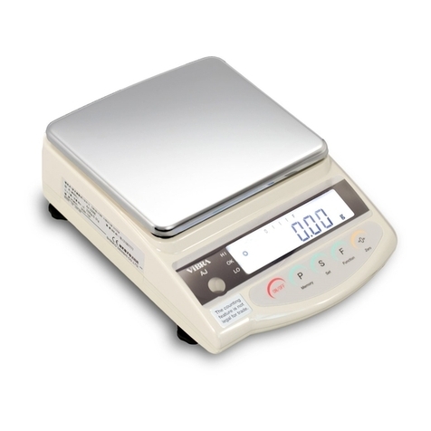
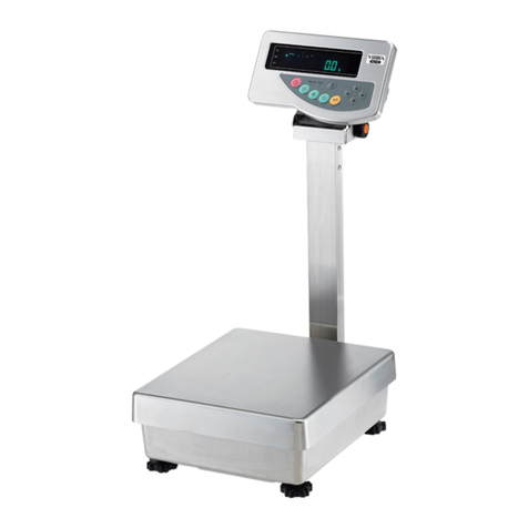
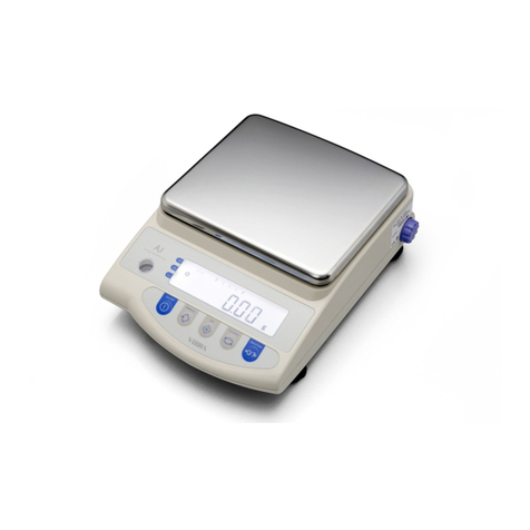
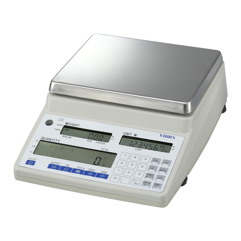
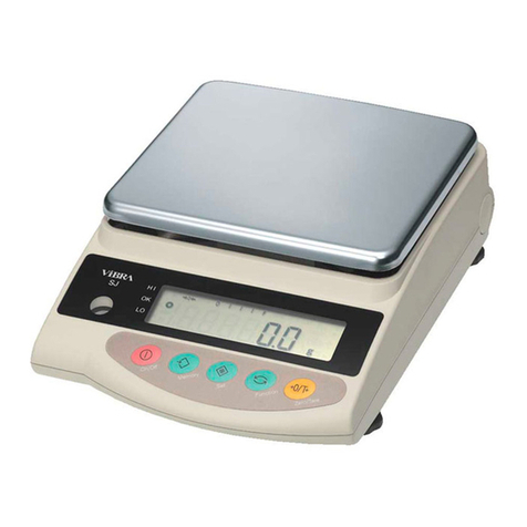
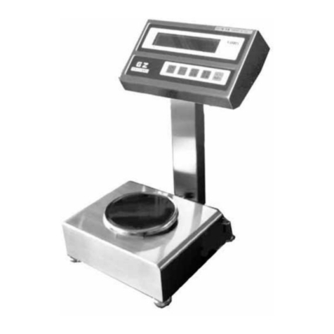
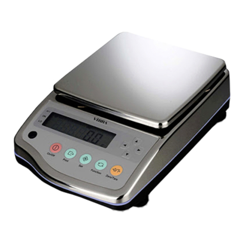
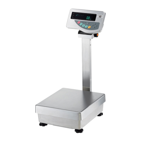
Vibra HJ-K Series User manual

i
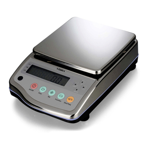
Precision Tuning-Fork Platform Scale
HJK Series
Operation Manual
SHINKO DENSHI CO., LTD.
IMPORTANT
To ensure safe and proper use of the scale, please read this
manual carefully.
After reading this manual, store it in a safe place near the scale,
so you can review it as needed.

ii
Preface
Thank you very much for having purchased Precision Tuning Fork Platform Scale HJK series. This
document describes how to operate the product.
Instructions
● The copyright of this document belongs to SHINKO DENSHI CO., LTD.. Reprinting or
duplicating of all or part of this document without notice shall not be allowed.
● Please note that product improvement or modification may cause partial discrepancy between
the product and the description of this document.
● The description of this document is subject to change without notice.
● This document has been created carefully. In case that, however, any error or imperfection is
found by any chance, please let us know.
● Documents of which pages are missing or irregularly bound will be exchanged. Please inform
the store where you purchased the product.
● Trouble related to the product or system will be dealt with in accordance with the individual
maintenance contract. Please note, however, that we will not take responsibility for
consequential trouble such as discontinuation of operation caused by the product trouble.
● is the registered trademark of SHINKO DENSHI CO., LTD.. Company names and
product names appearing in this document are the trademarks or registered trademarks of the
respective company concerned.

iii
Important Notice
It should be known that this product contains potential danger. And so
please be sure to observe this document when installing, operating or
servicing this product.
SHINKO DENSHI CO., LTD. will not take any responsibility for any injury or
damage caused by the non-observance of this document or misuse or
unauthorized modification of this product.
● Potential dangers are increasing in the
industrial equipment industries due to the advent
of new materials, new processing methods and speeding up of machines. It is
impossible to foresee all situations related to these dangers. In addition, there are so
many “impossible” and “don’ts” and so wri
ting all of them in the operation manual is
impossible. Therefore, it is safe to think that what is not written in the operation manual
“cannot be performed” unless the operation manual positively writes “it is possible.”
When performing installation, oper
ation, maintenance or inspection of this product, not
only observe what is written or indicated in this document or on the product surface but
also pay adequate consideration to safety measures.
● For any question or further information concerning this do
cument, please contact the
store where you purchased the product with its model (type) name and serial number
informed.
● Manufacturer: SHINKO DENSHI CO., LTD.
Address: 3-9-11 Yushima, Bunkyo-ku, Tokyo 113-0034 JAPAN

iv
How to use this document
■Symbols used in this document
Understand the meaning of the following symbols and observe the instructions of this document.
Symbols Meaning
Used for high risk point concerning the operations that may lead to death or
severe physical injury to persons if proper precautions are not taken.
Used for warning concerning the operations that may lead to death or severe
physical injury to persons, if proper precautions are not taken.
Used for caution concerning operations that may lead to a light physical injury
to persons if proper precautions are not taken.
Used for notation concerning operations that may lead to damage of
the products/facilities/data if proper precautions are not taken.
Used for accurate weighing and appropriate usage of the equipment.
Used for referenced information which is useful for product operation.
Used for “Prohibition” items
Used for “Mandatory” items requiring positive action
Used for prohibition items to avoid “Electrical shock”.
This symbol indicates the operation/specification in related to the verified
scale for legal metrology.
This product/
The product/The scale Refers to the product.
[KEY NAME] key The name of an operation key located on the indicator unit is represented in
square brackets “[ ]”.
<MESSAGE> A message on the display is represented in angle brackets “< >”.
<<ITEM>> Displayed menu item assigned to each functional key is represented in
double angle brackets “<< >>”.
Press the key Signifies pressing lightly an operation key once.
Press the key long Signifies keeping pressing an operation key until the designated
indication/operation occurs.

v
Contents
Preface ........................................................................................................................................... i
Important Notice.......................................................................................................................... iii
How to use this document ......................................................................................................... iv
Contents ....................................................................................................................................... v
1 Prior to use ................................................................................................................................ 1
1-1Operating precautions ....................................................................................................... 1
1-2For more accurate measurement ...................................................................................... 3
1-2-1Precautions related to measuring environment .............................................................. 3
1-2-2Precautions related to measuring table .......................................................................... 3
1-2-3Precautions related to a specimen ................................................................................. 4
1-2-4Precautions related to the main unit of a scale .............................................................. 4
1-3Check for the articles contained in the box ....................................................................... 5
1-4Name of each section ....................................................................................................... 6
1-5Assembling and installation of the product ........................................................................ 7
1-5-1(1) Procedure for installing the separate type scale without integrating the indicator unit . 7
1-5-1(2) Procedure for installing the separate type scale with integrating the indicator unit ...... 8
1-5-2 Procedure for connection with AC adapter and peripherals ....................................... 10
1-5-3Level ............................................................................................................................. 11
1-6How to carry the scale ..................................................................................................... 12
1-7Description of the operation keys .................................................................................... 13
1-7-1Basic ............................................................................................................................ 13
1-7-2Setting value and numeric value inputting ................................................................... 14
1-8How to interpret the display ............................................................................................. 15
1-8-1Description of segment ................................................................................................ 15
1-8-2LCD character font ....................................................................................................... 16
2 Basic usage .......................................................................................................................... 17
2-1Turning on/off the power, and checking for the operation ................................................ 17
2-2Zero-point adjustment ..................................................................................................... 17
2-3Weighing samples with container (tare) .......................................................................... 18
2-4Weighing the additional sample ...................................................................................... 19
2-5Basic operation ............................................................................................................... 19
2-5-1Hierarchy of a setting menu ......................................................................................... 19
2-5-2Operation of the setting menu ...................................................................................... 20
2-5-3Numeric value input ..................................................................................................... 21
2-5-4Functional keys switching at each measuring mode .................................................... 22
3 Functions related to the operation ...................................................................................... 23
3-1Hierarchy of functions related to the operation ................................................................ 23
3-2Various measuring modes of the scale ........................................................................... 25
3-2-1Weighing mode ............................................................................................................ 25
3-2-2Counting mode ............................................................................................................. 25
3-2-2 (1) Actual value setting method ...................................................................................... 26
3-2-2 (2) Numeric value setting method ................................................................................... 28
3-2-2 (3) Switching the display at Counting mode ................................................................... 28
3-3Percentage mode ............................................................................................................ 29
3-3-1Switching the display at percentage mode ................................................................... 30
3-4Multiplied by Coefficient mode ........................................................................................ 31
3-4-1Switching the display at Multiplied by Coefficient ......................................................... 32
3-5Unit setting ...................................................................................................................... 32
3-6Comparator function ........................................................................................................ 33
3-6-1How to perform discrimination ...................................................................................... 33
3-6-2Comparator function setting ......................................................................................... 34
3-7Adding function ............................................................................................................... 35

vi
3-7-1Weighing by means of addition .................................................................................... 36
3-8Stabilization wait setting .................................................................................................. 37
3-9Bar graph indication ........................................................................................................ 37
3-10Backlight setting ............................................................................................................ 37
3-11Auto power-off ............................................................................................................... 38
3-12Buzzer setting ............................................................................................................... 38
3-13“Simple SCS(Self Counting System) method” setting ................................................... 39
3-14Range mode setting ...................................................................................................... 39
4 Functions related to the performance ................................................................................ 40
4-1Hierarchy of functions related to the performance ........................................................... 40
4-2Stability discrimination width ........................................................................................... 40
4-3Response speed ............................................................................................................. 41
4-4Zero tracking ................................................................................................................... 41
5 Preset tare and Comparator setting .................................................................................... 42
5-1Hierarchy of Preset tare and Comparator setting ............................................................ 42
5-2Preset tare....................................................................................................................... 43
5-2-1Preset tare setting ........................................................................................................ 43
5-2-2Inputting of a preset tare weight value ......................................................................... 43
5-2-2 (1) Actual value setting method ...................................................................................... 44
5-2-2 (2) Numeric value setting method ................................................................................... 44
5-2-2 (3) Exiting the preset tare mode ..................................................................................... 44
5-3Setting of the discrimination value of the comparator function ........................................ 45
5-3-1Actual value setting method ......................................................................................... 46
5-3-2Numeric value setting method ...................................................................................... 46
6 External input/output functions .......................................................................................... 47
6-1Hierarchy of the external input / output functions ............................................................ 47
6-2Connector terminal numbers, their functions and specifications ..................................... 48
6-2-1D-SUB9P Connector for RS232C I/O........................................................................... 48
6-2-2D-SUB9P Connector for serial output for peripherals................................................... 49
6-3Communication format .................................................................................................... 49
6-3-1Basic data output format / CSP format ......................................................................... 49
6-3-2CBM data output format ............................................................................................... 51
6-4Input command ............................................................................................................... 52
6-4-1Transmission procedure ............................................................................................... 52
6-4-2Input command composition 1 ..................................................................................... 53
6-4-2 (1) Zero-point adjustment/Tare/Output control setting command .................................... 53
6-4-2 (2) Date output request and time output request ............................................................ 53
6-4-2 (3) Span adjustment/test command ................................................................................ 54
6-4-3Input command composition 2 ..................................................................................... 54
6-4-3 (1) Comparator setting command ................................................................................... 54
6-4-3 (2) Preset tare value setting command ........................................................................... 54
6-4-3 (3) Interval (output) time setting command ..................................................................... 54
6-5Response ........................................................................................................................ 55
6-5-1Response command format (A00/Exx format) ............................................................. 55
6-5-1(1) Response command .................................................................................................. 55
6-5-2Response command format (ACK/NAK format) ........................................................... 55
6-5-2(1) Response command .................................................................................................. 55
6-6Communication setting .................................................................................................... 55
7 Functions related to the lock ............................................................................................... 57
7-1Hierarchy of functions related to the lock ........................................................................ 57
7-2Total lock release ............................................................................................................ 57
7-3Key lock function ............................................................................................................. 58
7-4Menu lock function .......................................................................................................... 58
8 Controlling and adjustment functions ................................................................................ 59
8-1Hierarchy of controlling and adjustment functions ........................................................... 59

vii
8-2Shortcut setting for accessing various measuring modes ............................................... 61
8-3Free key setting ............................................................................................................... 62
8-4Adjustment and test ........................................................................................................ 63
8-4-1Span adjustment and span test .................................................................................... 63
8-4-1(1) Span adjustment with external weight ........................................................................ 63
8-4-1(2) Span test with external weight .................................................................................... 65
8-4-1(3) Semi-Automatic Span adjustment with internal weight ............................................... 66
8-4-1(4) Span test with internal weight ..................................................................................... 66
8-4-2Calibrating the internal weight ...................................................................................... 67
8-4-3Restore the internal weight calibration value to default ................................................ 69
8-4-4Advice CAL .................................................................................................................. 69
8-5Scale control setting ........................................................................................................ 70
8-5-1Scale ID setting ............................................................................................................ 70
8-5-2Password control ......................................................................................................... 70
8-5-2 (1) Administrator password registration .......................................................................... 71
8-5-2 (2) User password registration........................................................................................ 71
8-5-3Outputting of the span adjustment / test result ............................................................. 72
8-5-4Date indication format .................................................................................................. 72
8-5-5Date setting .................................................................................................................. 72
8-5-6Time setting ................................................................................................................. 73
8-5-7Output language .......................................................................................................... 73
8-5-8Readability Setting ....................................................................................................... 74
8-5-9Span adjustment with internal weight at power-on ....................................................... 74
8-5-10Direct start setting ...................................................................................................... 75
8-5-11Save tare weight function ........................................................................................... 75
8-5-12Initialise ...................................................................................................................... 76
9 Troubleshooting ................................................................................................................... 77
9-1Error message ................................................................................................................. 77
10 How to clean the scale ....................................................................................................... 79
Appendix ..................................................................................................................................... 80
Appendix 1Specifications ..................................................................................................... 80
Appendix 1-1Basic Specifications ........................................................................................ 80
Appendix 1-2Functional specifications ................................................................................. 82
Appendix 2Dimensional outline drawing ............................................................................... 84
Appendix 3Unit conversion table .......................................................................................... 85
Appendix 4Weighing capacity and readability by non-metric units ....................................... 86
Appendix 5Scale operation with password control function .................................................. 87
Appendix 5-1User’s authority setting .................................................................................... 87
Appendix 5-2User/guest login .............................................................................................. 88
Appendix 6Operation with internal rechargeable battery ...................................................... 89
Appendix 6-1Specifications of battery .................................................................................. 89
Appendix 6-2Recharging battery .......................................................................................... 89

1
1 Prior to use
1-1 Operating precautions
■Do not wet the AC adapter.
That may cause an electric shock, short-circuiting or failure.
■Do not expose the AC adapter to dust.
That may cause an electric shock, short-circuiting or failure.
■Do not handle the AC adapter with wet hands.
That may cause an electric shock, short-circuiting or failure.
■Do not use the scale in a dust-filled room.
That may cause dust explosion or fire.
■Do not use the scale in explosive atmosphere.
That may cause explosion or fire.
Please order our explosive-proof scales to weigh in such a hazardous area.
■Obey the MSDS.
Measuring dangerous materials such as flammable liquid could cause an explosion or fire.
■Do not disassemble or modify the product.
Doing so could result in injury, electric shock, fire and other accidents or failures. For inspection and
adjustment, contact the retailer from whom the product was purchased.
■Do not move the product with a sample to be weighed set on the scale.
That may cause the sample to fall from the weighing pan, leading to a bodily injury or destruction of the
sample.
■Do not route the cables across passages.
The cables could be tripped on by a passed by and the scale could fall down and break or injure
someone.
■Do not use the product on an unstable table or a place that is subject to vibration.
That may cause the sample to fall from the weighing pan, leading to a bodily injury or destruction of the
sample. Besides inaccurate weighing may result.
■Do not place an unstable sample on the weighing pan.
The sample may fall down, giving rise to a danger. Put an unstable sample in a container (tare) before
weighing it.
■Do not use the product in an abnormal condition.
If it should happen that an abnormal event such as smoking or unusual odor occurs, ask the store
where you purchased the product or our sales department for repair. Keeping using the product may
result in an electric shock or fire. In addition, do not ever try to repair it for yourself, or very dangerous
situation is likely to occur.
■Only use the dedicated AC adapter.
Use of other types of power or adapters may result in heat generation or malfunction of the scale.

2
■Do not use the indicator unit in a wet/dusty location when AC adapter jack cover or
D-sub 9p connector covers are opened.
That may cause an electric shock, short-circuiting or failure.
■Do not connect to the AC adapter cord or communication cable with its connector or
jack being wet.
That may cause an electric shock, short-circuiting or failure.
■Do not install the scale in a place where it is directly exposed to airflow from air-
conditioning or heating equipment.
Due to changes in the ambient temperature, the scale could fail to accurately weigh samples.
■Do not install the scale in a place exposed to direct sunlight.
The internal temperature of the scale could rise, and the scale could fail to accurately weigh samples.
■Do not install the scale where the floor is soft.
When a sample is placed on the scale, the scale could slant and fail to accurately weigh samples.
■Do not install the scale in a place where the ambient temperature or humidity
change significantly.
The scale could fail to accurately weigh samples.
■Do not apply excessive force to or impact the scale.
Doing so could damage or result in failure of the scale. Carefully place samples on the scale.
■Do not use volatile solvents for cleaning anything other than the weighing pan.
The key panel, dust/waterproof packing or other resin components of could deform, and the scale no
longer maintains the dust/waterproofness. Wipe each unit using dry cloth or a cloth moistened with a
small amount of neutral detergent.
■Adjust (calibrate) the scale when it is installed or relocated.
Failure to do so might result in measurement errors. To ensure accurate measurements be sure to
adjust (calibrate) the scale.
■Check for an error periodically.
Use environment and chronological change cause an error in measured value, leading to an inaccurate
measurement.
■Unplug the AC adapter from the receptacle when the scale is not going to be used
for a long period of time.
Unplug the scale from the receptacle to save energy and prevent degradation.
■Always adjust the level of the scale before use.
A tilted scale generates errors which might cause inaccurate weighting.
■For proper disposal
This product including accessories may not be disposed of in domestic waste in conformance with
the specific requirements in your country, such as the European Directive 2012/19/EU on waste
electrical and electronic equipment (WEEE).
When you dispose of this product, please contact your local authorities or dealer and ask for the correct
method of disposal.

3
1-2 For more accurate measurement
To make more accurate measurement, it is necessary to lessen error-causing factors in measurement to
the extent possible. Error-causing factors include not only an instrument error and performance of the
scale itself but also the nature and condition of a specimen, measuring environment (vibration,
temperature, humidity, etc.) and the like. These factors will directly affect measurement result in the case
of a scale with high resolution capability.
1-2-1 Precautions related to measuring environment
Temperature/
humidity/
atmospheric
pressure
→
Try to keep the room temperature constant to the extent possible in order to
avoid condensation and indication drift due to change in temperature.
→
Low humidity is likely to cause generation of static electricity, resulting in
inaccurate measurement.
→
Change of atmospheric pressure is likely to cause change of buoyancy of the air
on the specimen, tare and mechanism of the scale, resulting in inaccurate
measurement.
Vibration/shaking
→
It is preferable to locate a measuring room on the first floor or the basement. The
higher the room is, the larger the vibration and shaking become. Therefore, a
highly located room is not suitable for measurement. Rooms near the railway or
road side should also be avoided.
Air draft →
Places directly exposed to air current from an air-conditioner or to direct sun
generate abrupt temperature change and resultantly cause unstable weight
indication, and therefore, should be avoided.
Gravity →
The latitude and altitude of a measuring location differentiate the gravity that
affects a specimen, giving a different weight indication to the same specimen.
Electromagnetic
wave
→
At a location where a strong electromagnetic wave generating object is in the
proximity of a scale, the scale is affected by the electromagnetic wave, making
the scale unable to indicate accurate weight, and therefore, such a location
should be avoided.
1-2-2 Precautions related to measuring table
Vibration/shaking
→
Vibrations during measurement destabilizes the indication of measurement
value, leading to inability to make accurate measurement. And so use of a
measurement table that is robust and hardly affected by vibration is required (a
vibration-proof structured table or concrete or stone-made table is suitable). In
addition, placing a sheet of soft cloth or paper under the scale causes shaking or
makes keeping horizontal attitude difficult, and therefore should be avoided.
→
The measurement table should be installed in a position free from vibration to the
extent possible. A corner rather than the centre of a room is less affected by
vibration and therefore more suitable for installation of the scale.
Magnetism/Static
electricity
→
Use of the scale on the table that is subject to magnetism or static electricity
should be avoided.

4
1-2-3 Precautions related to a specimen
Static
electricity
→
In general, synthetic resin- and glass-made specimens are high in electric insulation,
and so easily charged electrically. Weighing an electrically charged specimen makes
the indication value unstable, reducing the reproducibility of the test result. Therefore,
neutralize an electrically charged specimen before measurement.
Magnetism →
Specimens affected by magnetism show different weight in a different position of the
weighing pan, reducing the reproducibility.
When weighing a magnetized specimen, either eliminate the magnetism from the
specimen or place a setting plate on the weighing pan to distance the specimen from
the weighing mechanism of the scale so that the mechanism may not be affected by
the magnetism.
Moisture
absorption/
Evaporation
→
Measuring a moist or evaporating (vaporizing) specimen increases or decreases the
indication value of the scale continuously. When this is the case, put the specimen in
a container equipped with a small mouth and closely seal the mouth before
measurement.
1-2-4 Precautions related to the main unit of a scale
Operating
precautions
→
A dust cover, if equipped, for the scale may possibly make the weight indication
unstable due to static electricity charged on the cover at a low humidity. When this is
the case, wipe the cover with wet cloth or use antistatic agent or use the scale with
the cover removed.
→
For more stable measurement, it is recommended to energize the scale for longer
than 30 minutes and load the scale a few times with a weight equivalent to the
weighing capacity before measurement.
Adjustment →
Calibrate the scale periodically with an external adjustment weight or internal
adjustment weight. For the sake of precise calibration, use an external adjustment
weight weighing nearly equal to the weighing capacity of the scale.
→
Energize the scale for longer than 30 minutes and load the scale a few times with a
weight equivalent to the weighing capacity before adjustment.
→
Adjustment is also needed in the following cases:
When using the scale for the first time,
When using the scale after a long period of non-use,
When changing a place of installation, and
When there was a large change in temperature, humidity or atmospheric pressure.
Maintenance
→
Attachment of dirt such as powder or liquid to the weighing pan or pan base will
cause measurement error or unstable weight indication. For that reason, frequent
cleaning of the scale is required.

5
1-3 Check for the articles contained in the box
The package box contains the following;
If anything missing or broken should be found, please inform the store where you purchased the product.
①Weighing unit and indicator set: 1
②Cable cover: 1
③Base cover: 1
④Indicator mounting bracket: 1
⑤AC adapter: 1
AC adapter plug set: 1
⑥Operation manual: 1

6
1-4 Name of each section
1 Indicator unit 2 Weighing unit
3 Weighing Pan 4 Level
5 Adjusters (Adjustable legs) 6 AC adapter jack
* Mount the connector cover when not connected.
7 Scale cable (Unremovable) 8
RS-232C connector (D-sub 9 pin male)
* Mount the connector cover when not connected.
9
Connector for peripheral devices
(D-sub 9 pin male)
* Mount the connector cover when not
connected.
10
Cover of hanging hook
(The hook for hanging is an option. For more
information, refer to the instruction manual for the
hook for hanging.)
* Close the cover to protect against dust and water
when not in use.

7
1-5 Assembling and installation of the product
1-5-1(1) Procedure for installing the separate type scale without integrating the
indicator unit
1
Remove the weighing pan of the weighing unit.
2
Slightly open both sides of the cable cover and mount it vertically in the
cable housing.
Then mount the base cover in the front of the cable housing so that it is hooked
on the cable cover.
3
Put back the weighing pan.

8
1-5-1(2) Procedure for installing the separate type scale with integrating the indicator
unit
1
Remove the weighing pan of the weighing unit.
2
Loosen the two knobs in the indicator mounting bracket and mount it
vertically in the cable housing.
Check that the supporting boards are hooked on the bottom of the cable
housing.
Then fasten the knobs.
3
Fold the cable and put it in the cable housing with 15 cm of the cable left unfolded
in the indicator-unit’s end.
4
Slightly open both sides of the cable cover and mount it vertically in the cable
housing.

9
5
Put back the weighing pan.
6
Then insert the indicator unit in the indicator mounting bracket at an angle.
7
Mount the base cover vertically.

10
1-5-2 Procedure for connection with AC adapter and peripherals
(1)
(2)
Be sure the AC adapter jack and Dsub-9p connectors not being wet.
When not connected, be sure not leave covers of the AC adapter jack and Dsub-9P
connectors open.
1
Remove the covers for D-sub 9P connectors and connect RS232C cables
when necessary
2
Put the AC adapter plug to the AC adapter, remove the cap of AC adapter
jack.
3
Remove the cover for AC adapter jack and connect AC adapter.

11
1-5-3 Level
1
Release the transportation lock of the
adjuster.
At the time of shipment, the adjusters provided
at the four corners of the bottom are locked.
Turn them in the direction shown in the figure on
the left to loosen them.
2
Level the scale.
(1)
While watching the level, turn the adjusters
provided on the bottom to level the main unit.
(2)
Bring the bubble enters in the centre circle as
shown in the figure on the left.
(3)
When having levelled the main unit, slightly
push the four corners of the scale to make
sure that there is no rattle.

12
1-6 How to carry the scale
(1)
(2)
(3)
Make sure not to carry the scale with the cable hanging.
Make sure not to carry the scale with weighing object on the weighing pan.
Wearing the safety shoes and work gloves is highly recommended.
This product is heavy and should be carried according to the following manual.
1. Unplug AC adapter and interface cables.
2. When the separate type, bundle the scale cable not to hang on the floor.
3. Holding position to lift up and carry: Bottom surface of the scale. Do not grab the weighing
pan or indicator unit.
4. Using a hand truck trolley is highly recommended. When using it, lay cushioning material on
it to prevent impact to the scale.
Be careful not to apply excessive force to or impact the scale.
Do not grab here.
Grab here.

13
1-7 Description of the operation keys
1-7-1 Basic
No
Key Name of key
Performance
1
[On/Off] Turns on and off the power for the scale.
On: Press the key, Off: Press the key long
2
[Menu]
Used for calling/exiting the setting menu.
Used for cancelling the setting value selection and going back to the
measuring mode.
3
[Output] Use for data outputting.
4
[Zero] Use for zero-point adjustment.
5
[Tare] Use for tare subtraction.
6
[1]
<
<
>
>
:
:
Use for selecting the mode, function and item.
Use for moving up to the menu/item selections, or use
for incrementing the numeric values.
7
[2]
<
<
>
>
:
:
Use for selecting the mode, function and item.
Use for moving down to the menu/item selections, or use
for decrementing the numeric value.
8
[3]
<
<
>
>
:
:
Use for selecting the mode, function and item.
Use for moving to the upper menu layer, or use for
selecting the digit to change.
9
[4]
<
<
<
>
>
>
:
:
:
Use for selecting the mode, function and item.
Use for moving to the lower menu layer, or use for
selecting the digit to change.
Use for entering/executing the selected
menu/item/value, or use for returning to the setting
menu/measuring mode.
The functional keys on which < >, < >, < >, < >, < > or < > are displayed above
are valid.
Shortcuts for various modes/functions can be assigned to each functional key. Please refer to
“8-2 Shortcut setting for accessing various measuring modes” and “8-3 Free key setting”.
These keys are collectively called
“functional keys” in this manual
as a matter of convenience.
Other manuals for HJ-K Series
1
Table of contents
Other Vibra Scale manuals

Vibra
Vibra DJ series User manual

Vibra
Vibra TPS SERIES User manual

Vibra
Vibra CG-K User manual

Vibra
Vibra SJ-6200 CE User manual

Vibra
Vibra FZ623E Series User manual

Vibra
Vibra ALE-NC Series User manual

Vibra
Vibra AJ220NT/DBNT User manual

Vibra
Vibra SJ-E Series User manual

Vibra
Vibra GZII-CEx Series User manual

Vibra
Vibra GZ II Series User manual

Vibra
Vibra SJ-CE series User manual

Vibra
Vibra VIBRA HAW 3 User manual

Vibra
Vibra AJ Series User manual

Vibra
Vibra DJ-150E User manual

Vibra
Vibra AJ-CESeries User manual

Vibra
Vibra VIBRA ALC 3 User manual

Vibra
Vibra HJ-KCE series User manual

Vibra
Vibra CJ series User manual

Vibra
Vibra AF-220 User manual

Vibra
Vibra CUX Series User manual