T
T
Ta
a
ab
b
bl
l
le
e
e
o
o
of
f
f
C
C
Co
o
on
n
nt
t
te
e
en
n
nt
t
ts
s
s
Conditions and Cautions for
Installation
1 Conditions of Installation (for the
Explosion-Proof Type)......................... 1, 2
2 Cautions about Installing the Scale .......... 3
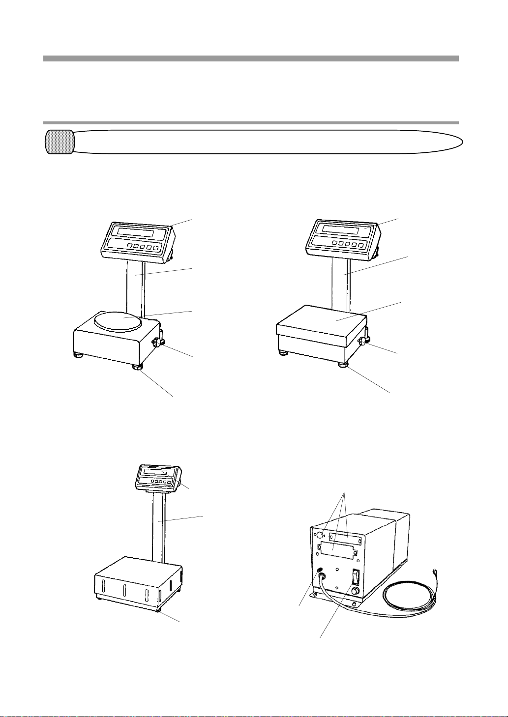
Names and Functions of the
Component Parts
1 Outer View.............................................. 4
2 Details of the Panel ................................. 5
Installation
1 Checking Supplied Items......................... 6
2 Cautions about Installation ...................... 7
3 Assembling a Small-Sized Scale.............. 8
4 Assembling a Medium-Sized Scale.......... 9
4 Horizontal Adjustment of the Scale........ 11
5 Installation of the Power Supply Box..... 12
6 How to Replace Batteries ...................... 13
Basic Operation of the Scale
1 Getting Started and Checking Operation 14
3 Taring and Weighing ............................. 15
4 Notes on Handling the Scale.................. 16
Addition Function
1 Select the Addition Function.................. 17
2 Procedure for Making Addition and
Displaying the Sum..........................18, 19
Limit Function
1 Select the Limit function...................20, 21
2 Setting by Weighing Actual Samples .22, 23
3 Setting by Entering Values ..............24, 25
Functions
1 Functions and How They Work..........26, 27
2 Checking the Set Value ...........................28
3 Change the Setting..................................29
Calibration of the Scale
.........................................................30, 31
Troubleshooting
...............................................................32
Standard Specifications
1 Common Specifications...........................33
2 Configuration of Each Model ..................34