Viale Vicenza 14
36063 Marostica VI - Italy
www.vimar.com
02692 01 2204
02692 - Ceiling-mounted connected radar sensor
SMART HOME VIEW WIRELESS
Thanks to UWB (radar ultra wide band) ultra-low power technology, the sensor is capable of
detecting presence and possible fallen people with the utmost precision. The device is fitted
with an input for external wired contact which can be configured to control the activation of the
relay or to activate the scenarios in the View Wireless system. The front push button starts the
configuration with the View Wireless App and the LED signals the status of the relay.
TWO OPERATING MODES (ALTERNATIVE)
Stand alone •View Wireless System
Download the View Wireless App from the stores onto the tablet/smartphone you
will be using for configuration.
Depending on the mode you select, you will need:
Stand alone View Wireless System
Nothing else
Gateway art. 30807.x-20597-19597-16497-14597
View App for management via smartphone/tablet
When the device is powered for the rst conguration, we recommend you search for any
new rmware and perform the update.
Create your Installer account on MyVimar (on-line).
STAND ALONE CONFIGURATION
1.Wire all the radar sensors.
2.Start the View Wireless App and log in with the credentials you just created.
3.Create the system and the environments.
4.Associate all the sensors with the environments.
To associate the radar sensor:
• Select “Add” ( ), choose the environment to place it and give it a name
• Select ; activate the Bluetooth connection on your tablet/smartphone and approach the
radar sensor
• Press the front push button to start the Configuration phase
5.For every device, set the function, the parameters and any accessory devices (wired or radio
control and related function).
CONFIGURATION IN THE VIEW WIRELESS SYSTEM
1.Wire all the devices in the system (radar sensors, 2-way switches, thermostats, gateway, etc.).
2.Start the View Wireless App and log in with the credentials you just created.
3.Create the system and the environments.
4.Associate all the devices with the environments, except for the gateway (which should be
associated last).
To associate the radar sensor:
• Select “Add” ( ), choose the environment to place it and give it a name
• Select ; activate the Bluetooth connection on your tablet/smartphone and approach the
radar sensor
• Press the front push button to start the Configuration phase
5.For every device, set the function, the parameters and any accessory devices (wired or radio
control and related function).
6.Transfer the configuration of the devices to the gateway and connect it to the Wi-Fi network.
7.Transfer the system to the Administrator user (who must have created his/her profile on
MyVimar).
For details please refer to the View Wireless App manual you can download from www.
vimar.com DOWNLOAD View Wireless MOBILE App
Summary of LED signals
• During normal operation (default colours):
LED Meaning
On white Relay active
Off Relay not active
On red Fall detection
Flashing white
Manual forcing
(Relay active without timer activated/deactivated with
front push button pressing)
• In the configuration phase:
LED Meaning
Flashing blue
(for max 2 min.) Pending receipt of a fw update
1 green flash Connection established with View Wireless
Blue permanently lit Device associated with the smartphone via Bluetooth
1 white flash Device reset
RESETTING THE DEVICE.
The reset restores the factory settings. Within the first 5 minutes from powering, press the front
push button
for 30 s until the white LED flashes.
INSTALLATION RULES.
• Installation and configuration must be carried out by qualified persons in compliance with the
current regulations regarding the installation of electrical equipment in the country where the
products are installed.
• Installation must be carried out with the system switched off.
• The OUT terminals are separated by double insulation from the L-N-P terminals. Do not
connect a mains voltage circuit to the OUT terminals; these terminals can be connected to
SELV and ELV circuits according to the characteristics stated.
• Connect a double insulated cable or a reinforced cable type 01840.E to the OUT terminals.
• Use a cable with sheath for terminals L-N-P (type H05RN-F) with the dedicated cable clamp.
• The device may only be used for indoor applications.
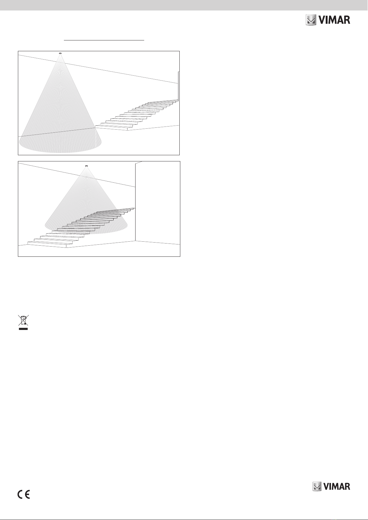
• Metal objects in front of the detector tend to alter its operation. Avoid installations where metal
surfaces are present in the radar’s field of detection.
• The technology used is capable of detecting presence even through certain types of material
(for instance plasterboard, thin walls, fabric and wood), so suitable installation in the room is
necessary, as is the appropriate configuration of the maximum detection range.
• Do not install on partitions or walls subjected to shock and vibration.
• This device is compliant with the reference standard, in terms of electrical safety, when it is
installed as specified in the instructions and with the accessories supplied. If the device is used
for purposes other than those specified by the manufacturer, the protection provided may be
compromised.
• Do not cover the detection range of the detector.
• Install the device at a distance of more than 2 m from any Wi-Fi 6E antennae.
• After the configuration phase (or after changing parameters) and every time it is switched on,
the detector performs an initial calibration phase lasting 45 s at the end of which it becomes
operational; during this phase, detection may not be precise.
• Presence detection of a sleeping person only occurs correctly if the subject is entirely inside the
detection area.
CHARACTERISTICS:
• Rated supply voltage: 100-240 V~, 50/60 Hz.
• Max. power absorption from the mains: 1.1 W
• Output contact: 24 VAC or 30 VDC, 400 mA max (SELV and ELV), not suitable for controlling
electrical locks
• Bluetooth technology:
- RF transmission power: < 100 mW (20 dBm)
- Frequency range: 2400-2483.5 MHz
• UWB radar:
- RF transmission power: < 1mW (0 dBm)
- Frequency range: 7.3÷8.5 GHz
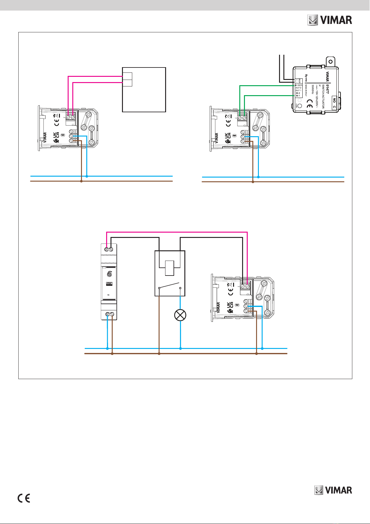
•Terminals:
- 2 terminals (L and N) for line and neutral
- 1 terminal (P) for connection to the remote wired control (for instance art. 30008-20008-
19008-16080-14008). The max distance between the IoT device and the push button is
50 m with a cable with a minimum cross-section of 1.5 mm2.
- 2 terminals (OUT) for the potential-free signal relay output for SELV and ELV circuits
• Front push button for configuration/reset and for manual forcing (in configurations in which this
mode is allowed).
• RGB LED indicating the output status (which can be set from the View Wireless App) and the
configuration status
• Operating temperature: -10 ÷ +40 °C (indoor)
• Protection degree: IP20
• Configuration via View Wireless App for View Wireless system in Bluetooth technology
• Controllable via View App
• Detection of a fall is to be considered an auxiliary function which generates useful
information to highlight conditions of danger, but it must not be deemed a substitute for a
medical/life-saving device.
OPERATION
Operation, and therefore the management of the relay, widgets and notifications displayed by
the View App are connected to the setting assigned to the parameters during the configuration
phase.
Presence function
The presence in the detection area is signalled in the View App for the full duration plus the
absence check time (75 s). At the end of this time, the relay is deactivated with a delay that can
be set between 1 s and 16 hours.
PRESENCE
RELAY
absence check t
relay off t
75 s