manuals.online logo
Brands
  1. Home
  2. •
  3. Brands
  4. •
  5. Vingtor Stentofon
  6. •
  7. Intercom System
  8. •
  9. Vingtor Stentofon Exigo Ex EAPFX-1 Guide

Vingtor Stentofon Exigo Ex EAPFX-1 Guide

Exigo Ex Access Panels & Turbine Ex Intercoms
Mounting Manual
Product Overview
Mounting procedures are the same for all units in the Exigo and Turbine Ex series.
Contents of this Delivery
The unit comes with 4 blind plugs already mounted. The front frame is fastened with 2 socket-head cap M6 screws.
Important Notes before Mounting
Improper installation and operation of the Ex unit will result in the invalidation of the warranty.
The enclosure/housing must not be opened when the unit is powered.
The installation and connection of Ex units may only be carried out by qualified/approved personnel
General Mounting Considerations
When the Ex unit is mounted directly onto a wall or mounting plate, it shall rest only on the fastening points provided for
this purpose. The surface must be even and flat.
The unit must be mounted on a surface to prevent access from the rear of the unit.
Do not use countersunk screws.
Due to the cabinet material, use as low a tightening torque as possible when mounting the unit to the surface (1.5 Nm max.)
Washers are recommended.
Do not use more than 2.5 Nm torque when fastening the 12 screws into the front frame.
On Mounting Plate or Column - recommended screws:
M5 x 20 or 25 with Philips head DIN7985 or Torx. Head diameter: 10 mm.
On Wall - recommended screws:
Panhead – DIN7981 for plug or wooden wall, etc. Head diameter: 10.8 B5.5 x 38 or 45 mm.
EAPFX-6
1023221516
EAPFX-1
1023221511
1 Cable Gland
M25 Ex e
Exigo Ex Access Panels & Turbine Ex Intercoms
Mounting manual
Station overview
Installation procedures are the same for all panels in the Industrial Ex series.
Contents of this delivery
Note! The unit are equipped with four blind plugs,front frame is fastened with 2 unbraco M6 screws
Important notes before mounting
Improper installation and operation of the Ex access panel will result in the invalidation of the guarantee.
The enclosure/housing must not be opened when the product is powered.
The installation and connection of Ex units may only be carried out by qualified / Approved personnel
Mounting, general
When the Ex Product is mounted directly onto a wall or mounting plate, it shall rest only on the fastening points provided for
this purpose.The surface must be even and flat.
The unit must be mounted on a surface to prevent access from the back
Do not use countersunk screws.
Due to the cabinet material, use as low a tightening torque as possible
Washers are recommended
Do not use more than 2.5 Nm torque when fastening the 12 screws in the front frame.
On Mounting plate or column, recommended screws:
M5 x 20 or 25 with Philips head DIN7985 or Torx. Head diameter 10mm.
On Wall, recommended screws:
Panhead – DIN7981 for plug or wooden wall, etc. Head diameter 10.8 B5.5 x 38 or 45 mm
EAPFX-6
1023221516
EAPFX-1
1023221511
1x Cable Gland
M25ATEX e
1x Cable Gland
M16ATEX e
10 x Unbraco
screw M6
1x Ex Station
TFIX-1
1008123010
TFIX-2
1008123020
TFIX-3
1008123030
This manual
1 Cable Gland
M16 Ex e
10 socket-head
cap M6 screws
(+ 2 fastened to
front frame)
1 Ex Unit
TFIX-1
1008123010
TFIX-2
1008123020
TFIX-3
1008123030
This Manual
TFIX-4
1008123040
Dimensions
1 Loosen the 2 screws
securing the front frame
to the on-wall box.
2Open the enclosure by
pulling the front frame out 5
mm, keeping it parallel to the
on-wall box. This is necessary
to get clearing for the hinges.
3 Pull the right side of the front
frame to open the enclosure fully.
Do NOT open the enclosure to the
extent that cables between the
front and back parts become taut.
Opening the Enclosure
Mounting the Unit
4 Preparation for Drilling
The four mounting holes in the on-
wall box are Ø6.4 mm. Distance: 298
x 130 mm. Size of hole to be drilled
depends on whether it is wall or
column mounting.
7 Wall
Fix the unit to the wall with 4 screws that fit the
4 screw holes in each corner of the on-wall box
(Ø6.4 mm). Use Panhead – DIN7981 screw for
plug or wooden wall.
Head Ø: 10.8 B5.5 x 38 or 45 mm.
6 Mounting Plate or Column
Fix the unit to the mounting plate or
column with 4 screws that fit the 4
screw holes in each corner of the
on-wall box (Ø6.4 mm). Use M5 x 20
or 25 with Philips head DIN7985 or
Torx. Head Ø: 10 mm.
5 Location
Make sure there is a clearance of
minimum 230 mm on the left for frame
movement.
Zenitel and its subsidiaries assume no responsibility for any errors that may appear in this publication, or for damages arising from the information therein. Vingtor-Stentofon products are developed and marketed by Zenitel. The company’s Quality Assurance System is certified to meet
the requirements in NS-EN ISO 9001. Zenitel reserves the right to modify designs and alter specifications without notice. ZENITEL PROPRIETARY. This document and its supplementing elements, contain Zenitel or third party information which is proprietary and confidential. Any disclosure,
copying, distribution or use is prohibited, if not otherwise explicitly agreed in writing with Zenitel. Any authorized reproduction, in part or in whole, must include this legend. Zenitel – All rights reserved.
DOC NO. DATE
www.zenitel.com
5.12.2018
Electrical Connections
8 Mounting Cable Gland
Remove two blind plugs and insert one
M16 Ex e and one M25 Ex e cable gland.
Make sure to tighten sufficiently to attain
IP-66 rating for watertightness, but be
aware of plastic material limitations.
For complete documentation, see Installation &
Maintenance Procedures for Exigo Ex Access
Panels & Turbine Ex Intercoms, Doc. no.
A100K11499.
Related Documentation
Document No. Documentation
A100K11499 Exigo & Turbine Ex Installation & Maintenance Procedures
A100K11460 Exigo Technical Manual
A100K11422 Flowire Installation & Configuration Manual
A100K11471 Exigo User Manual
A100K11194 Turbine Stations Configuration Manual
Accessories & Spare Parts
Item Number Item Name Item Description
AK5850HS AK5850HS Ex-Approved Headset with plug
1008150025 TAX-2B Ex-Approved Cable for Headset with PTT Button
1008150030 TAX-3 Ex-Approved Handset with PTT, unterminated
1023533511 EMMAX-1H Exigo Handheld Industrial Ex Microphone
1000150040 TAX-4 Cable gland kit (10x) for TFIX and EAPFX
1023594100 EGA-1 Button Protection Covers (10x)
1008140250 TA-25 M6 screw kit
In order to ensure the required minimum degree of protection,
the cable glands must be tightened securely.
Over-tightening can impair the degree of protection and
damage the Ex unit.
When tightening the cap nut of a cable gland, a suitable tool
shall be used to prevent the gland from twisting.
If there is an X sign after the Ex certificate number, this indi-
cates that the equipment is subject to special conditions for
safe use.
Special conditions for safe use:
The cable glands shipped with this product have an impact
resistance of maximum 4J. Due to low impact resistance of the cable
glands, the units shall only be installed in areas where there is a low
risk of impact.
If cable glands supporting high impact (7J) are used, the X
conditions do not apply.
PRESAFE 14ATEX5209X
IECEX PRE 14.0029X
Approved EB / 18.02.2015
A100K11523
The relevant certificates and declarations of conformity may be
downloaded from www.zenitel.com/customer-service/library
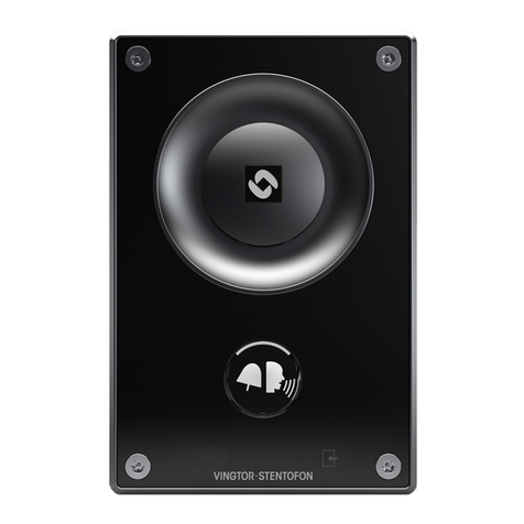
Other manuals for Exigo Ex EAPFX-1

1

This manual suits for next models

17

Other Vingtor Stentofon Intercom System manuals

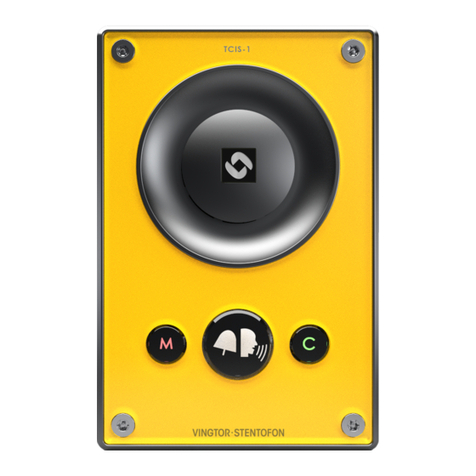
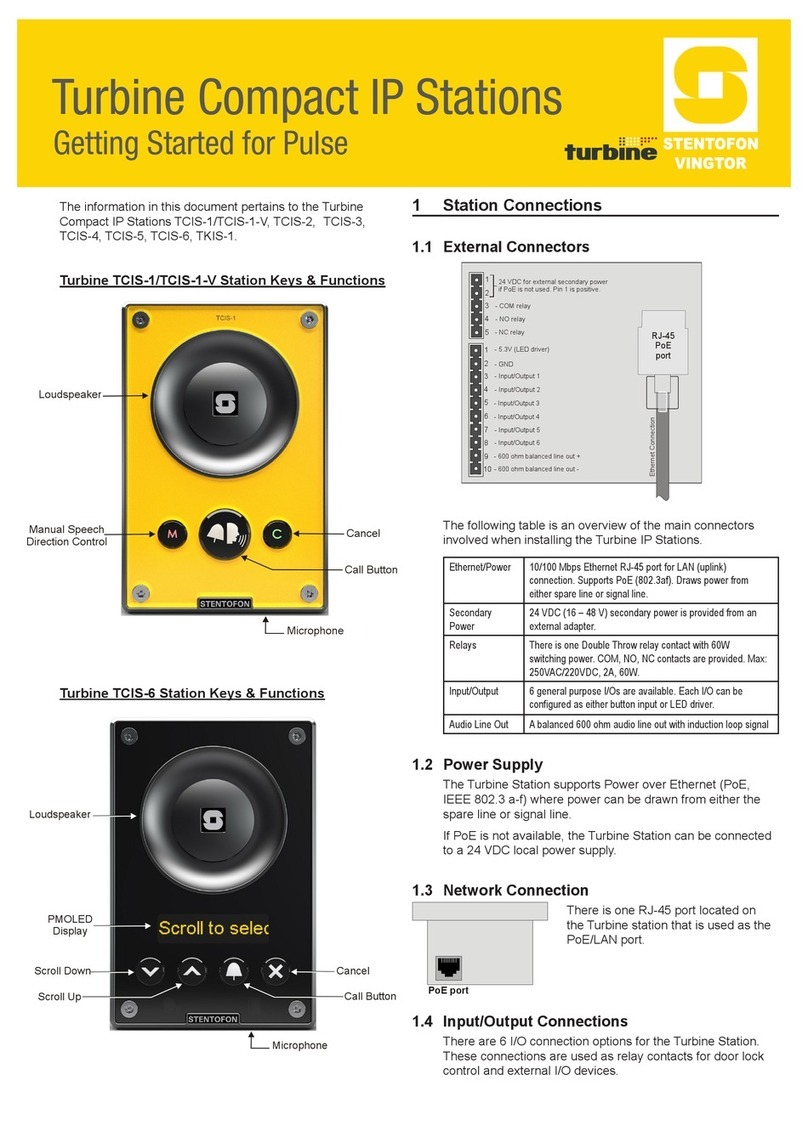
Vingtor Stentofon TCIS-1 Guide

Vingtor Stentofon

Vingtor Stentofon TCIS-1 Guide

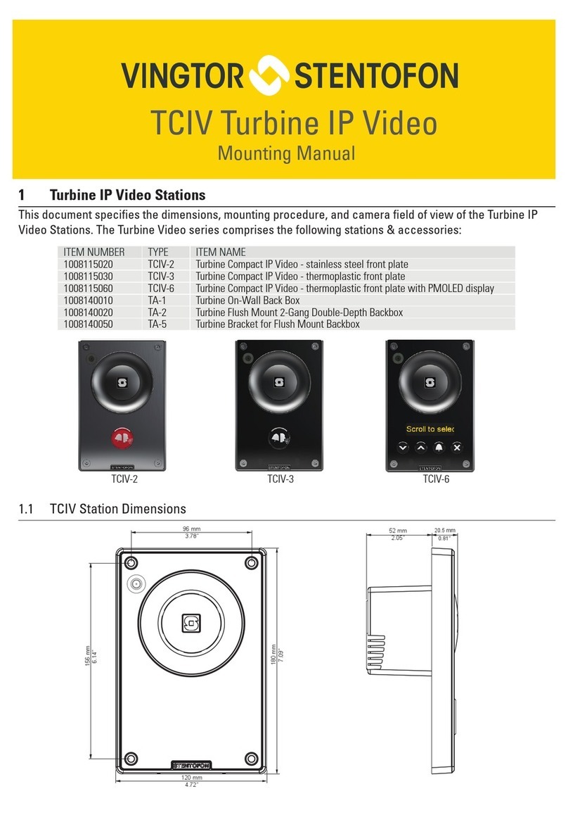
Vingtor Stentofon TCIV-2SIP Guide

Vingtor Stentofon

Vingtor Stentofon TCIV-2SIP Guide

Vingtor Stentofon ECPIR-3P User manual

Vingtor Stentofon

Vingtor Stentofon ECPIR-3P User manual

Vingtor Stentofon TCIS-1 User manual

Vingtor Stentofon

Vingtor Stentofon TCIS-1 User manual

Vingtor Stentofon TCIS Series User manual

Vingtor Stentofon

Vingtor Stentofon TCIS Series User manual

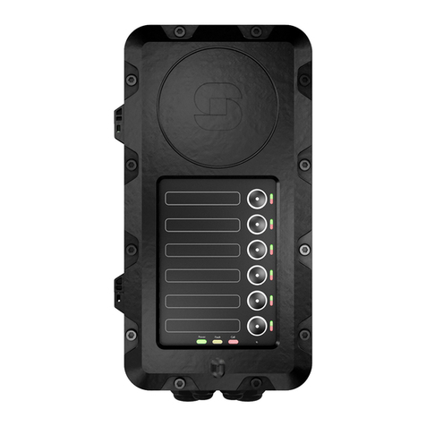
Vingtor Stentofon Exigo Ex EAPFX-1 User manual

Vingtor Stentofon

Vingtor Stentofon Exigo Ex EAPFX-1 User manual

Vingtor Stentofon ITSV-1 User manual

Vingtor Stentofon

Vingtor Stentofon ITSV-1 User manual

Vingtor Stentofon TCIS-1 User manual

Vingtor Stentofon

Vingtor Stentofon TCIS-1 User manual

Vingtor Stentofon TCIS-1SIP Guide

Vingtor Stentofon

Vingtor Stentofon TCIS-1SIP Guide

Vingtor Stentofon Turbine TMIS-1 Installation instructions manual

Vingtor Stentofon

Vingtor Stentofon Turbine TMIS-1 Installation instructions manual

Vingtor Stentofon Turbine Mini SIP Station Guide

Vingtor Stentofon

Vingtor Stentofon Turbine Mini SIP Station Guide

Vingtor Stentofon TFIE-1 Guide

Vingtor Stentofon

Vingtor Stentofon TFIE-1 Guide

Vingtor Stentofon TCIV-2 Guide

Vingtor Stentofon

Vingtor Stentofon TCIV-2 Guide

Vingtor Stentofon Turbine Compact Analog TCAS Series Guide

Vingtor Stentofon

Vingtor Stentofon Turbine Compact Analog TCAS Series Guide

Popular Intercom System manuals by other brands

Aiphone Tenant IXG Series Operation manual

Aiphone

Aiphone Tenant IXG Series Operation manual

Comelit 6722W Technical manual

Comelit

Comelit 6722W Technical manual

SSS Siedle Classic SET CLAB 850-1 Product information

SSS Siedle

SSS Siedle Classic SET CLAB 850-1 Product information

RTS User Station MCE-325 User instructions

RTS

RTS User Station MCE-325 User instructions

Vimar 6600 SERIES Installation and operation manual

Vimar

Vimar 6600 SERIES Installation and operation manual

sks BS2012 installation instructions

sks

sks BS2012 installation instructions

Linear Access RE-2 Installation, programming and operation instructions

Linear Access

Linear Access RE-2 Installation, programming and operation instructions

Aiphone VAM-10A instructions

Aiphone

Aiphone VAM-10A instructions

Viking E-30 Technical practice

Viking

Viking E-30 Technical practice

Pilot Communications PA-200T Operational guide

Pilot Communications

Pilot Communications PA-200T Operational guide

Intercom System HFX-700B Quick reference guide

Intercom System

Intercom System HFX-700B Quick reference guide

Bpt OPHERA US Instructions for use and installation

Bpt

Bpt OPHERA US Instructions for use and installation

ASM DPM-D277TMW manual

ASM

ASM DPM-D277TMW manual

2N Indoor Talk user guide

2N

2N Indoor Talk user guide

Federal Signal Corporation SELECTFONE SF-1245X-024 instruction sheet

Federal Signal Corporation

Federal Signal Corporation SELECTFONE SF-1245X-024 instruction sheet

Farfisa AGORA IPV11AGL manual

Farfisa

Farfisa AGORA IPV11AGL manual

Farfisa AD2121CAG series manual

Farfisa

Farfisa AD2121CAG series manual

Channel Vision ST-3108 Setup guide

Channel Vision

Channel Vision ST-3108 Setup guide

manuals.online logo
manuals.online logoBrands
  • About & Mission
  • Contact us
  • Privacy Policy
  • Terms and Conditions

Copyright 2025 Manuals.Online. All Rights Reserved.