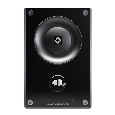
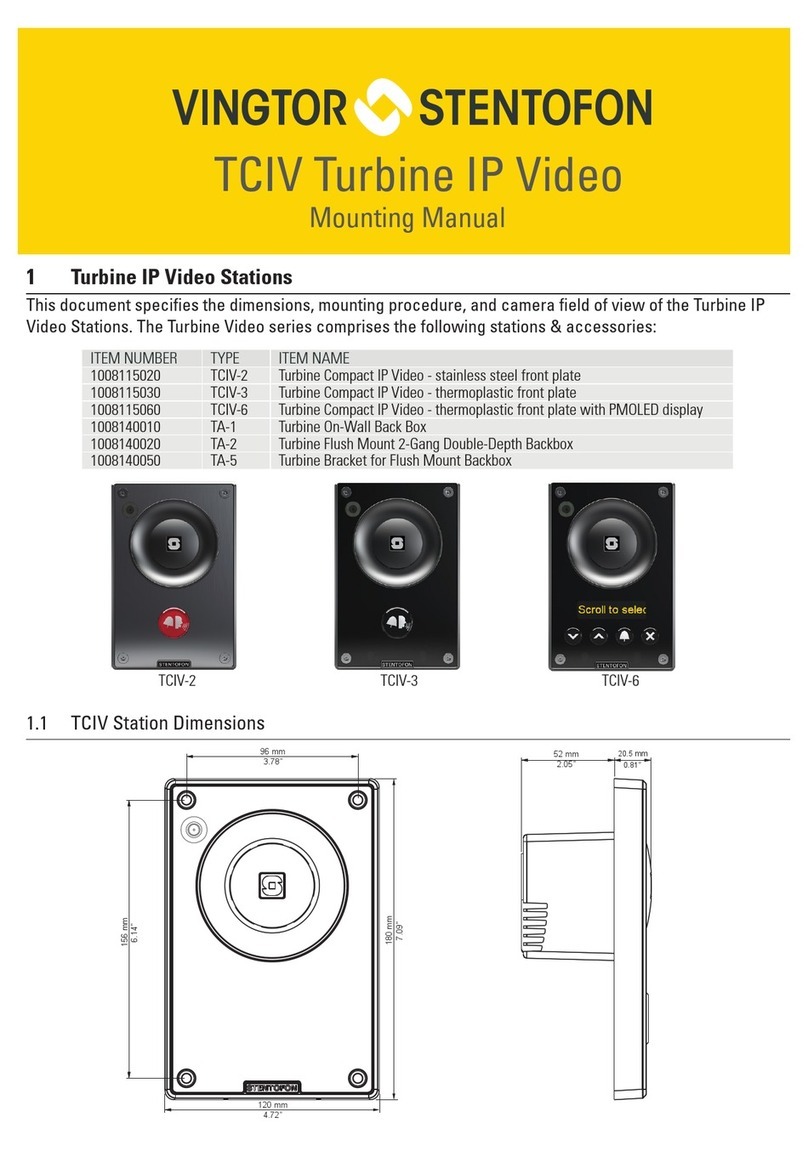
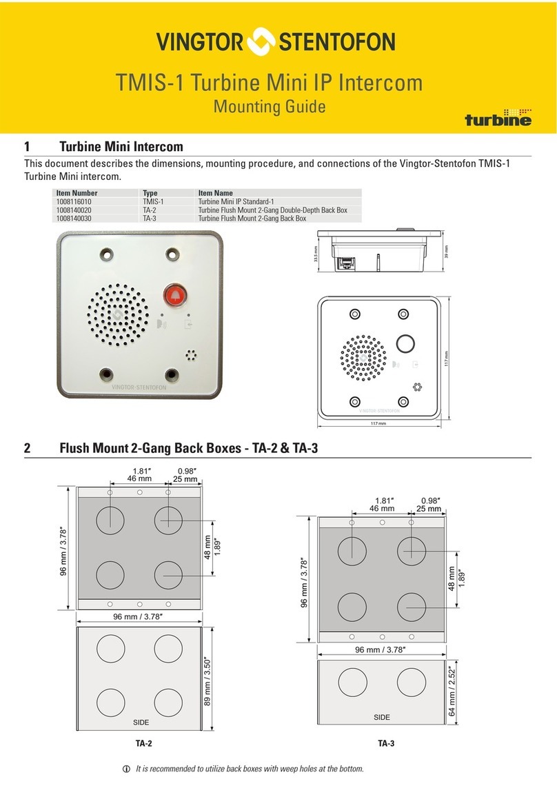
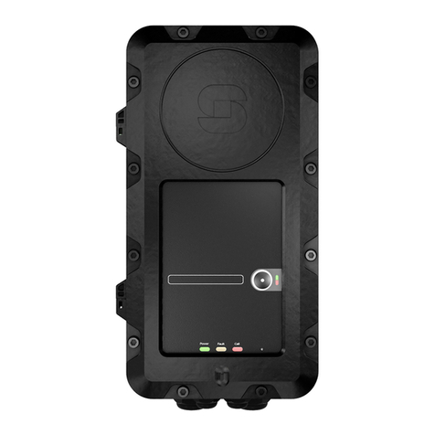
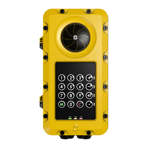
Vingtor Stentofon Exigo Ex EAPFX-1 User manual

Installation, & Maintenance Procedures
Ex schedule document.
All changes must be
approved by a Notied Body.

Ex Turbine Intercoms & Exigo Access Panels
Page 2Doc. no. A100K11499
Document Contents
1 Basic information
1.1 Revision history
Doc.no.
Rev.
Date
Prepared by
Revision text
App. by Ex responsible
A100K11499
1
05.01.2015
Svend E.Nilsen
New document
05.01.2015
Erik Bjørkander
A100K11499
1.1
05.02.2015
Svend E.Nilsen
Minor
correction,
labeled headset
as ATEX only
05.02.2015
Erik Bjørkander
A100K11499
1.2
03.03.2015
Thomas Hægh
Corrected IS
parameters
(chapter 3.3.2)
03.03.2015
Erik Bjørkander
1.2 Scope
This document describes the installation and maintenance procedures for
the VINGTOR - STENTOFON Exigo Ex Access Panels and Turbine Ex Intercom Stations,
henceforth commonly referred to as “Ex Products”, and their intended audio accessories.
The following models are covered by this manual.
Item number
Search name
Item Name
Exigo Ex PA access panels
1023221511
EAPFX-1
Exigo Industrial Ex Access Panel, 1 button, Flowire
1023221516
EAPFX-6
Exigo industrial Ex Access Panel, 6 buttons, Flowire
Turbine Ex intercom units
1008123010
TFIX-1
Turbine Full-Size Ex Intercom Station 1
1008123020
TFIX-2
Turbine Full-Size Ex Intercom Station 2
1008123030
TFIX-3
Turbine Full-Size Ex Intercom Station 3
1008123040
TFIX-4
Turbine Full-Size EX Intercom Station 4
Ex audio accessories
2330040026
AK5850HS
Ex-Approved Headset with plug **
1008150025
TAX-2B
Ex-Approved Cable for Headset with PTT Button
1008150030
TAX-3
Ex-Approved Handset with PTT, unterminated
1023533511
EMMAX-1H
Exigo Handheld Industrial Ex Microphone, 1 Button, IP66
** Headset AK5850HS is only certified for use in ATEX areas (Not IECEx)

Ex Turbine Intercoms & Exigo Access Panels
Doc. no. A100K11499 Page 3
1.3 Related Documentation
For further information, refer to the following documentation
Doc.no.
Documentation
A100K11460
Exigo Installation & Configuration Manual
A100K11422
Flowire Installation & Configuration Manual
A100K11471
Exigo User Manual
A100K11194
Turbine Stations Configuration Manual
A100K11523
Mounting Manual for EAPFX-1, EAPFX-6, TFIX-1, TFIX-2 , TFIX-3, TFIX-4
A100K11525
Connection Manual TAX-2b Ex-Approved plugbox and cable for Ex Headset
AK5850HS
A100K11526
Connection Manual TAX-3 EX-approved Handset w/PTT, unterminated
A100K11528
Connection Manual EMMAX-1H Exigo Handheld Industrial Ex Microphone
1.4 Certificates
ATEX Certificate number
Presafe 14ATEX5209 X
IECEx Certificate number
IECEx PRE 14.0029 X
Certificates can be downloaded from www.vingtor-stentofon.com
If the sign “X” is placed after the certificate number, it indicates that the equipment is subject to
special condition for safe use.
Special condition for safe use:
The cable glands shipped with this product has an impact resistance of max 4J.
Due to low impact resistance of the cable glands, the units shall only be installed in areas where
there is a low risk of impact.
If cable glands supporting high impact (7J) are used, the X condition does not apply.
2 About the Ex Products
2.1 The Industrial Ex product series
Before using this product, carefully read this manual and other manuals for compatible hardware.
Retain instructions for future reference.
The Ex Products are approved according to IECEx and ATEX regulations, and bear the marking:
II 2(2)G Ex e ib mb (ib) IIC T4 Gb (See chapter 3.5.4 marking for detailed information).
The following models and audio accessories are approved for use in hazardous areas

Ex Turbine Intercoms & Exigo Access Panels
Page 4Doc. no. A100K11499
EAPFX-1 EAPFX-6
TFIX-1 TFIX-2 TFIX-3 TFIX-4
AK5058HS** TAX-2B TAX-3 EMMAX-1H
Access
Panels
Intercoms
Audio
Accessories
** Headset AK5850HS is only certified for use in ATEX areas (Not IECEx)

Ex Turbine Intercoms & Exigo Access Panels
Doc. no. A100K11499 Page 5
2.2 Ex Product Interface
The interface of the Ex Products consist of the elements in the following chapters.
2.2.1 Status LEDs
Present on all Ex Products.
Green Power LED
The Power LED is lit to indicate that the access panel is powered up.
The Power LED flashes to indicate that the device has no connection to the central equipment.
Yellow Fault LED
The Fault LED is lit to indicate that there are faults in the system.
The Fault LED flashes to indicate that the device is connected to (link OK), but not registered with
the central equipment.
Red Call LED
The Call LED is lit when an intercom is in a conversation, or the microphone on an access panel is
active.
2.2.2 Function Buttons
Present on all Ex Products.
These are fully programmable buttons which appear in different forms on different units.
Right-aligned Function Buttons have two programmable LEDs (green and red) to indicate status
information related to the function.
For right-aligned Function Buttons, button protection covers can be attached to avoid a button
being inadvertently pressed.
2.2.3 Numeric Keypad
Present on TFIX-1, TFIX-3 and TFIX-4.
These have a predetermined function.
Dialing buttons 0 - 9, present on TFIX-1 and TFIX-4, are used for calling specific numbers or
triggering functions.
M-button, present on TFIX-1, TFIX-3 and TFIX-4, is used for answering calls, Push-To-Talk and
changing from external to internal audio devices.
C-button, present on TFIX-1, TFIX-3 and TFIX-4, is used to cancel a current action or state.

Ex Turbine Intercoms & Exigo Access Panels
Page 6Doc. no. A100K11499
2.2.4 Model specific interfaces
EAPFX-1
One right-aligned Function
Button
Available area for labelling the
button
EAPFX-6
Six right-aligned Function
Buttons
Available areas for labelling
the button

Ex Turbine Intercoms & Exigo Access Panels
Doc. no. A100K11499 Page 7
TFIX-1
Dialing buttons 0-9
M-button
C-button
Four function buttons, three of which
are pre-programmed:
+ for volume up
- for volume down
Audio button for changing
between loud speaking and
low speaking mode
TFIX-2
Six right-aligned Function
buttons
Available areas for labelling
the button

Ex Turbine Intercoms & Exigo Access Panels
Page 8Doc. no. A100K11499
TFIX-3
Call button
M-button
C-button
TFIX-4
Dialing buttons 0-9
M-button
C-button
Four function buttons,
three of which are pre-
programmed:
+ for volume up
- for volume do
Audio button for
changing between loud
speaking and low
speaking mode

Ex Turbine Intercoms & Exigo Access Panels
Doc. no. A100K11499 Page 9
2.3 Accessories
The following accessories are designed for use with any of the Ex Products.
AK5850HS
Headset with boom microphone, curled cord and plug
Plugs into TAX-2B
Headset AK5850HS is only certified for use in ATEX
areas (Not IECEx)
TAX-2B
10 m cable with Push-To-Talk button (PTT) and
contact
For headset AK5850HS
Terminated on main board inside Ex Product

Ex Turbine Intercoms & Exigo Access Panels
Page 10 Doc. no. A100K11499
TAX-3
Handset with Push-To-Talk button (PTT)
Terminated on main board inside Ex Product
EMMAX-1H
Microphone with Push-To-Talk button
Terminated on main board inside Ex Product

Ex Turbine Intercoms & Exigo Access Panels
Doc. no. A100K11499 Page 11
3 System design overview
3.1 Connection to central equipment
The Ex Products are connected to the central equipment rack using Ex certified 2-wire cable with
shield. A Zenitel proprietary protocol, Flowire, is used to extend the Ethernet connection and
support power distribution on the 2-wire cabling infrastructure.
To support the Flowire interface, the central equipment rack must be equipped with a Flowire
Converter (FCDC2).
Central
Equipment Rack
Flowire Converter,
FCDC2 (100 8080 210) Ex Access Panel
Safe Zone Hazardous Zone
Power Supply
24VDC
Ethernet
Ex Certified 2wire cable
with screen
Network configuration 1

Ex Turbine Intercoms & Exigo Access Panels
Page 12 Doc. no. A100K11499
Central
Equipment Rack
A
Flowire Converter,
FCDC2 (100 8080 210) Ex Access Panel
Safe Zone A
Hazardous Zone
Power Supply
24VDC
Ethernet
Ex Certified 2wire cable
with screen
Central
Equipment Rack
B
Flowire Converter,
FCDC2 (100 8080 210)
Safe Zone B
Power Supply
24 VDC
Ethernet
Ex Certified 2wire cable
with screen
Network configuration 2 - redundant cabling in Ex zone

Ex Turbine Intercoms & Exigo Access Panels
Doc. no. A100K11499 Page 13
3.2 Block diagrams for electronics (HW)
The Ex Products all use the same Printed Circuit Board Assemblies. These are:
A100C08127 –Front Board
A100C08511 –Main Board
The front board implements the user interface.
The main board implements the main functions. The board has the following interfaces:
Interface to internal loudspeaker
Interface to internal microphone
Interface to audio accessories (headset, handset, handheld microphone)
Interface to central equipment (Flowire)
The block diagram below shows the main components used in the Ex Panel design including
connectors, barrier sections and cable entries.

Ex Turbine Intercoms & Exigo Access Panels
Page 14 Doc. no. A100K11499
3.3 Electrical parameters
The Ex Products are designed for the following input and output parameters.
3.3.1 Internal Microphone and Loudspeaker
Microphone Input
Terminal J13 + -
Loudspeaker Output
Terminal J9 8-9
Uo
4.5V
Uo
6.3V
Io
44mA
Io
660mA
Po
0.5W
Po
01.1W
Co
100 uF
Co
100 uF
Lo
40 mH
Lo
0.3 mH
Details on the loudspeaker and microphone are found in Chapter 6 Technical Data.
3.3.2 Audio Accessories
Microphone Input
Terminal J6-3 / J7-4
Loudspeaker Output
Terminal J6 1-2
PTT Switch Input / Hook Switch input
Terminal J7 5-6
Uo
5.8V
Uo
5.8V
Uo
5.8V
Io
952mA
Io
952mA
Io
952mA
Po
1008mW
Po
1008mW
Po
1008mW
Co
597nF
Co
597nF
Co
597nF
Lo
40µH
Lo
40µH
Lo
40µH
The parameters above are a combination of all outputs connected together that can occur if
separation distances in external accessories are below the limits in EN60079-11:2012.
Technical specification on the accessories are found in Chapter 6 Technical Data.
Only Ex-certified audio accessories which comply with the input and output values in
chapter 3.3.2 may be used with the Ex Products.
The following Zenitel accessories comply with the input and output values stipulated above, and
are approved for use with the Ex Products:
Ex audio accessories
2330040026
AK5850HS
Ex-Approved Headset with plug **
1008150025
TAX-2B
Ex Approved Cable for Headset with PTT Button
1008150030
TAX-3
Ex-Approved Handset with PTT, unterminated
1023533511
EMMAX-1H
Exigo Handheld Industrial Ex Microphone, 1 Button, IP66
** Headset AK5850HS is only certified for use in ATEX areas (Not IECEx)

Ex Turbine Intercoms & Exigo Access Panels
Doc. no. A100K11499 Page 15
3.4 Terminals and connectors
Terminal J8 and J10 Type Phoenix MK3DSH 3/ 2-5, 08-EX
Hole diameter
1.3 mm
Screw thread
M3
Tightening torque, min
0.5 Nm
Tightening torque max
0.6 Nm
Conductor cross section solid min.
0.2 mm²
Conductor cross section solid max.
4 mm²
Conductor cross section stranded min.
0.2 mm²
Conductor cross section stranded max.
2.5 mm²
Terminal J13, J6, J7 and J9 Type Phoenix 1710049
Hole diameter
1.3 mm
Screw thread
M3
Tightening torque, min
0.5 Nm
Tightening torque max
0.6 Nm
Conductor cross section solid min.
0.2 mm²
Conductor cross section solid max.
4 mm²
Conductor cross section stranded min.
0.2 mm²
Conductor cross section stranded max.
2.5 mm²
Conductor cross section stranded, with ferrule without plastic sleeve min.
0.25 mm²
Conductor cross section stranded, with ferrule without plastic sleeve
max.
1.5 mm²
Conductor cross section stranded, with ferrule with plastic sleeve min.
0.25 mm²
Conductor cross section stranded, with ferrule with plastic sleeve max.
2.5 mm²
Conductor cross section AWG/kcmil min.
24
Conductor cross section AWG/kcmil max
12
2 conductors with same cross section, solid min.
0.2 mm²
2 conductors with same cross section, solid max.
1.5 mm²
2 conductors with same cross section, stranded min.
0.2 mm²
2 conductors with same cross section, stranded max.
1.5 mm²
2 conductors with same cross section, stranded, ferrules without plastic
sleeve, min.
0.25 mm²
2 conductors with same cross section, stranded, ferrules without plastic
sleeve, max.
0.75 mm²
2 conductors with same cross section, stranded, TWIN ferrules with
plastic sleeve, min.
0.5 mm²
2 conductors with same cross section, stranded, TWIN ferrules
with plastic sleeve, max.
1.5 mm²

Ex Turbine Intercoms & Exigo Access Panels
Page 16 Doc. no. A100K11499
3.5 Ex Protection Strategy
The Ex panel shall comply with the following standards:
IEC 60079-0: Explosive atmospheres - Equipment - General requirements
IEC 60079-7: Explosive atmospheres - Equipment protection by increased safety "e"
IEC 60079-11: Explosive atmospheres - Equipment protection by intrinsic safety "i"
IEC 60079-18: Explosive atmospheres - Equipment protection by encapsulation "m"
3.5.1 Increased safety “e”
The mechanical enclosure complies with requirements for increased safety (Ex "e").
The Ex "e" part of the main board includes the Flowire screw terminals.
3.5.2 Encapsulation “m”
Encapsulating the entire board ensures compliance with requirements for protection by
encapsulation (Ex “m”). Encapsulation removes the risk of sparks and provides thermal
protection to ensure that the surface temperature of the potting compound is below T4 limit
(135 °C).
The level of protection is "b" to comply with zone 1 equipment.
3.5.3 Intrinsic safety “i”
The following parts comply with requirements for intrinsic safety (Ex “i”):
A100C08127 - Turbine Front Board Extended
EMMAX-1H - Exigo Handheld Industrial Ex Microphone, 1 Button
AK5850HS Ex-Approved Headset with plug
TAX-2 - Turbine Ex Approved Headset, Pluggable
TAX-2B - Turbine Ex Approved Cable for Headset with PTT
TAX-3 - Turbine Ex Approved Handset with PTT, Unterminated
The barrier design on the main board provides “b” level protection (Ex ib) to the intrinsically
safe parts, supporting zone 1 requirements.
Um: 250V

Ex Turbine Intercoms & Exigo Access Panels
Doc. no. A100K11499 Page 17
3.5.4 Marking
Based on the requirements of zone 1, T4 and the chosen concept of protection, the Ex Product
shall include the following marking:
II 2(2)G Ex e ib mb (ib)IIC T4 Gb
If the sign “X” is placed after the certificate number, it indicates that the equipment is subject to
special condition for safe use.
Special condition for safe use:
The cable glands shipped with this product has an impact resistance of max 4J.
Due to low impact resistance of the cable glands, the units shall only be installed in areas where
there is a low risk of impact.
If cable glands supporting high impact (7J) are used, the X condition does not apply.

Ex Turbine Intercoms & Exigo Access Panels
Page 18 Doc. no. A100K11499
3.5.5 Compliance
IECEx
IEC 60079-0:2011, IEC 60079-7:2006, IEC 60079-11:2011, IEC 60079-
18:2009
ATEX
EN 60079-0:2012, EN 60079-7:2007, EN 60079-11:2012, EN 60079-18:2009
Immunity
EN 60945, EN 61000-6-1, EN 61000-6-2, FCC-47 part 15B
Emissions
EN 60945, EN 61000-6-3, EN 61000-6-4, FCC-47 part 15B

Ex Turbine Intercoms & Exigo Access Panels
Doc. no. A100K11499 Page 19
4 Installation
4.1 General
Improper installation and operation of the Ex access panel will result in the invalidation
of the guarantee.
The enclosure/housing must not be opened when the product is powered.
The installation and connection of Ex units may only be carried out by qualified
approved personnel.
The maximum voltage (Um) that can be applied to the non-intrinsically safe connection
facilities of associated apparatus without invalidating the type of protection is 250V
Special condition for safe use
The “X” after the certificate number indicates that the equipment is subject to special condition for
safe use.
The cable glands shipped with this product has an impact resistance of max 4J.
Due to low impact resistance of the cable glands, the units shall only be installed in areas where
there is a low risk of impact.
If cable glands supporting high impact (7J) are used, the X condition does not apply.
4.2 Mounting
When the Ex Product is mounted directly onto a wall or mounting plate, it shall rest only on the
fastening points provided for this purpose. The surface must be even and flat.
The unit must be mounted on the surface to prevent access from the back.
To mount the panel:
1. Open the enclosure by loosening the 12 screws that secure the front frame to the on-wall
box.
2. Open the enclosure by pulling the front frame out 5 mm, keeping it parallel to the on-wall
box. This is necessary to get clearing for the hinges. Then pull the right side of the front
frame to fully open the enclosure. Make sure to not open the enclosure so far that cables
between the front and back parts are pulled tight.
3. Fix the station to the wall, mounting plate or column with four screws that fit the four screw
holes in each corner of the on-wall box (6.7 mm diameter). (Ref. drawing on page 22)
On Mounting plate or column
M5 x 20 or 25 with Philips head DIN7985 or Torx.
Head diameter 10mm.
On Wall
Panhead –DIN7981 for plug or wooden wall, etc.
Head diameter 10.8 B5.5 x 38 or 45 mm

Ex Turbine Intercoms & Exigo Access Panels
Page 20 Doc. no. A100K11499
Do not use countersunk screws.
Due to the cabinet material, use as low a tightening torque as possible
Washers are recommended
4. Carry out Electrical connections (chapter 4.3)
5. Move the front part back to its original position and fasten the 12 screws.
Do not use more than 2.5Nm torque when fastening the 12 screws in the front frame.
4.2.1 Opening the enclosure
1Open the enclosure
by loosening the 2
screws that secure the
front frame to the on-
wall box
2Open the enclosure
by pulling the front
frame out 5 mm,
keeping it parallel to
the on-wall box. This is
necessary to get
clearing for the hinges
3 Then pull the right side of
the front frame to fully open
the enclosure. Make sure to
not open the enclosure so far
that cables between the front
and back parts are pulled
tight.
Other manuals for Exigo Ex EAPFX-1
1
This manual suits for next models
11
Table of contents
Other Vingtor Stentofon Intercom System manuals
Vingtor Stentofon
Vingtor Stentofon TCIS-1SIP Guide

Vingtor Stentofon
Vingtor Stentofon ITSV-1 User manual

Vingtor Stentofon
Vingtor Stentofon TFIE-1 Guide

Vingtor Stentofon
Vingtor Stentofon Exigo Ex EAPFX-1 Guide

Vingtor Stentofon
Vingtor Stentofon TCIV-2 Guide

Vingtor Stentofon
Vingtor Stentofon Turbine Mini SIP Station Guide
Vingtor Stentofon
Vingtor Stentofon Turbine TMIS-1 Installation instructions manual

Vingtor Stentofon
Vingtor Stentofon TCIS-1 User manual
Vingtor Stentofon
Vingtor Stentofon TCIS-1 User manual

Vingtor Stentofon
Vingtor Stentofon Turbine Compact Analog TCAS Series Guide