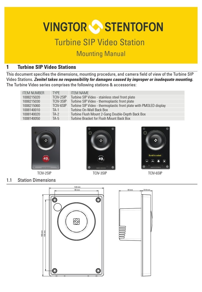
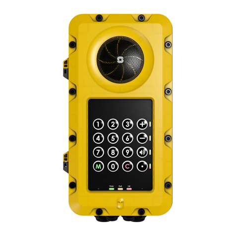
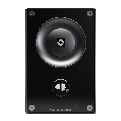
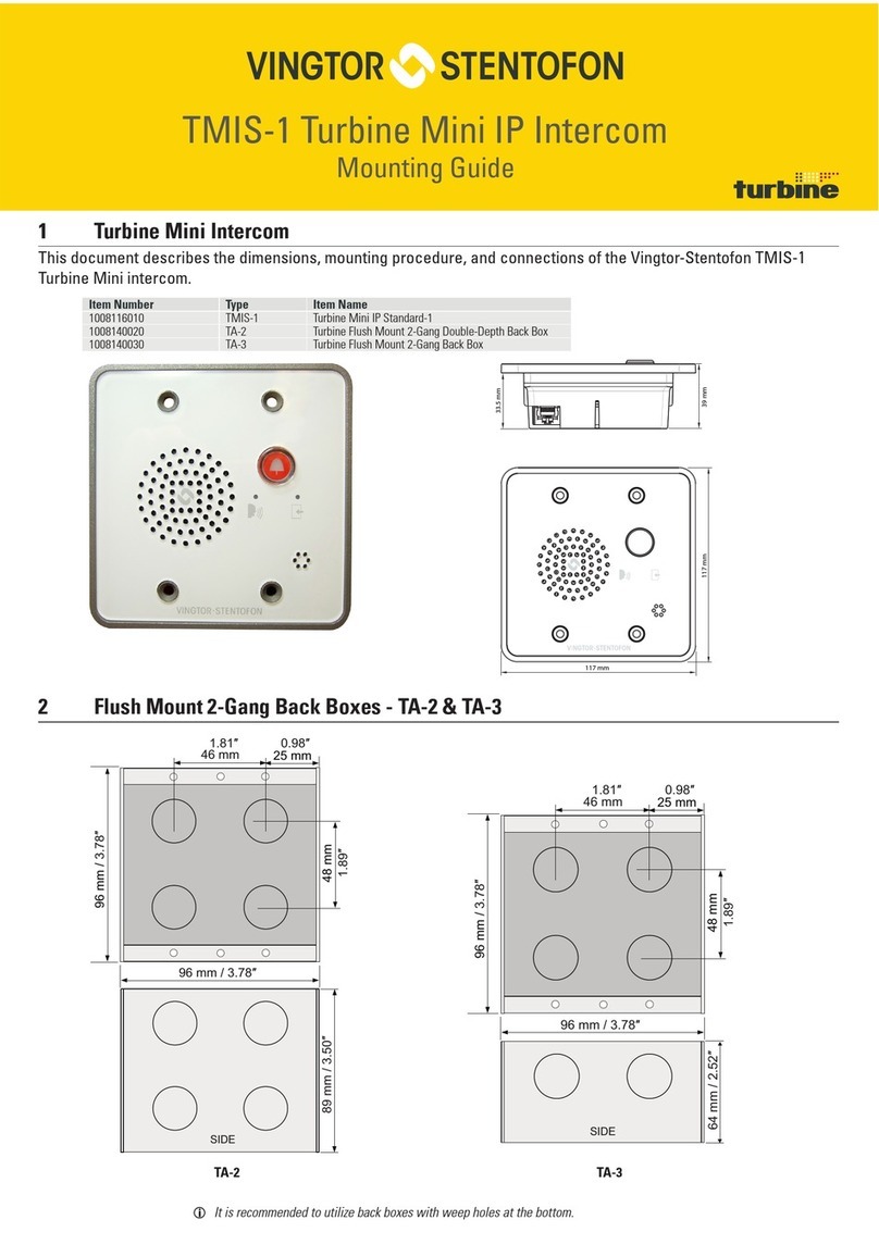
Vingtor Stentofon TCIS Series User manual

TECHNICAL MANUAL
Turbine IP Intercoms
TCIS / TCIV / TFIE / TFIX / TMIS / ECPIR-3P
A100K11194
PRE 14.0029

About this Document
Document Scope
This document describes the setup procedure and conguration of the various models of the Turbine
Compact and Extended IP Intercom series. The conguration procedures described here are for the general
functions of the Turbine range. For information on more advanced features and settings, see Zenitel Wiki.
Firmware Version: VSF-Turbine 5.1 (software package vsft-5.1.3.0 or later)
Model Product Description Item No. Accessories
TFIE-1 Turbine Extended Industrial IP Intercom 1008122010 TA-23 Handset for Industrial Stations - 1008140230
EMMAI-2H Handheld Compact Mic for Industrial Stations - 1023533312
TA-22b Cable and Plugbox for AK5850HS Headset - 1008140225
TA-10 Connection Board with Relays for Turbine Industrial - 1008140100
TFIE-2 Turbine Extended Industrial IP Intercom 1008122020
TFIE-6 Turbine Extended Industrial IP Intercom 1008122060
TKIE-2 Turbine Extended Industrial Kit 1008132010
TFIX-1 Turbine Extended Ex IP Intercom 1008123010 Headset for Ex & Industrial Stations - AK5850HS
TAX-2b Cable and Plugbox for AK5850HS Headset - 1008150025
TAX-3 Handset for Ex Stations - 1008150030
EMMAX-1H Handheld Microphone for Ex Stations - 1023533511
TFIX-2 Turbine Extended Ex IP Intercom 1008123020
TFIX-3 Turbine Extended Ex IP Intercom 1008123030
TFIX-4 Turbine Extended Ex IP Intercom 1008123040
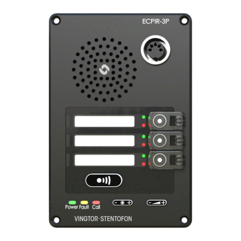
ECPIR-3P Turbine Extended Indoor Intercom 1023200033 PAM1H Handheld Microphone - 1023533012
EBMDR-8 8-Button Expansion Module - 1023253008
TMIS-1 Turbine Mini IP Intercom 1008116010
TMIS-2 Turbine Mini IP Intercom 1008116020
TCIS-1 Turbine Compact IP Intercom 1008111010 TA-1 Surface Mount Back Box - 1008140010
TA-2 Flush Mount 2-Gang Double-Depth Back Box - 1008140020
TA-5 Flush Mount Bracket - 1008140050
MRBD Multi Relay Board - 1009970200
TCIS-2 Turbine Compact IP Intercom 1008111020
TCIS-3 Turbine Compact IP Intercom 1008111030
TCIS-4 Turbine Compact IP Intercom 1008111040
TCIS-5 Turbine Compact IP Intercom 1008111050
TCIS-6 Turbine Compact IP Intercom 1008111060
TCIA-2 Turbine Compact IP Intercom 1008113020
TKIS-2 Turbine Compact VoIP Intercom Module 1008131020
Publication Log
Rev. Date Author Status
1.0 21.9.2012 HKL Published
2.0 24.9.2014 HKL Turbine Extended intercoms
2.1 5.2.2015 HKL TFIX-4 intercom
2.4 21.12.2016 HKL 802.1X authentication during upgrade
2.5 3.11.2017 HKL TFIE-6, VS-IS 4.7
3.0 June 2020 HKL IC-EDGE
Related Documentation
Doc. number Mounting Guides
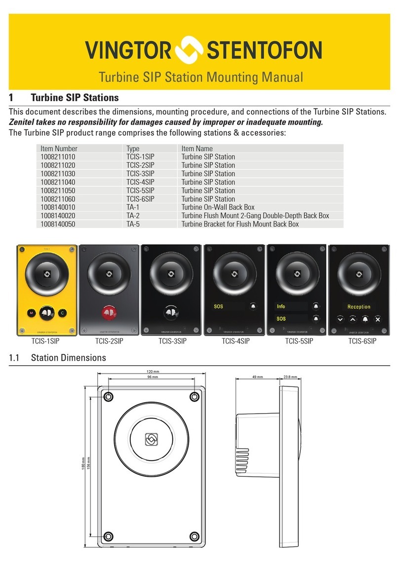
A100K11254 Turbine Compact IP Stations Mounting Guide
A100K11258 Turbine Compact Analog Stations Mounting Guide
A100K11523 Turbine Extended Ex Stations Mounting Guide
A100K11575 Turbine Extended Industrial Stations Mounting Guide
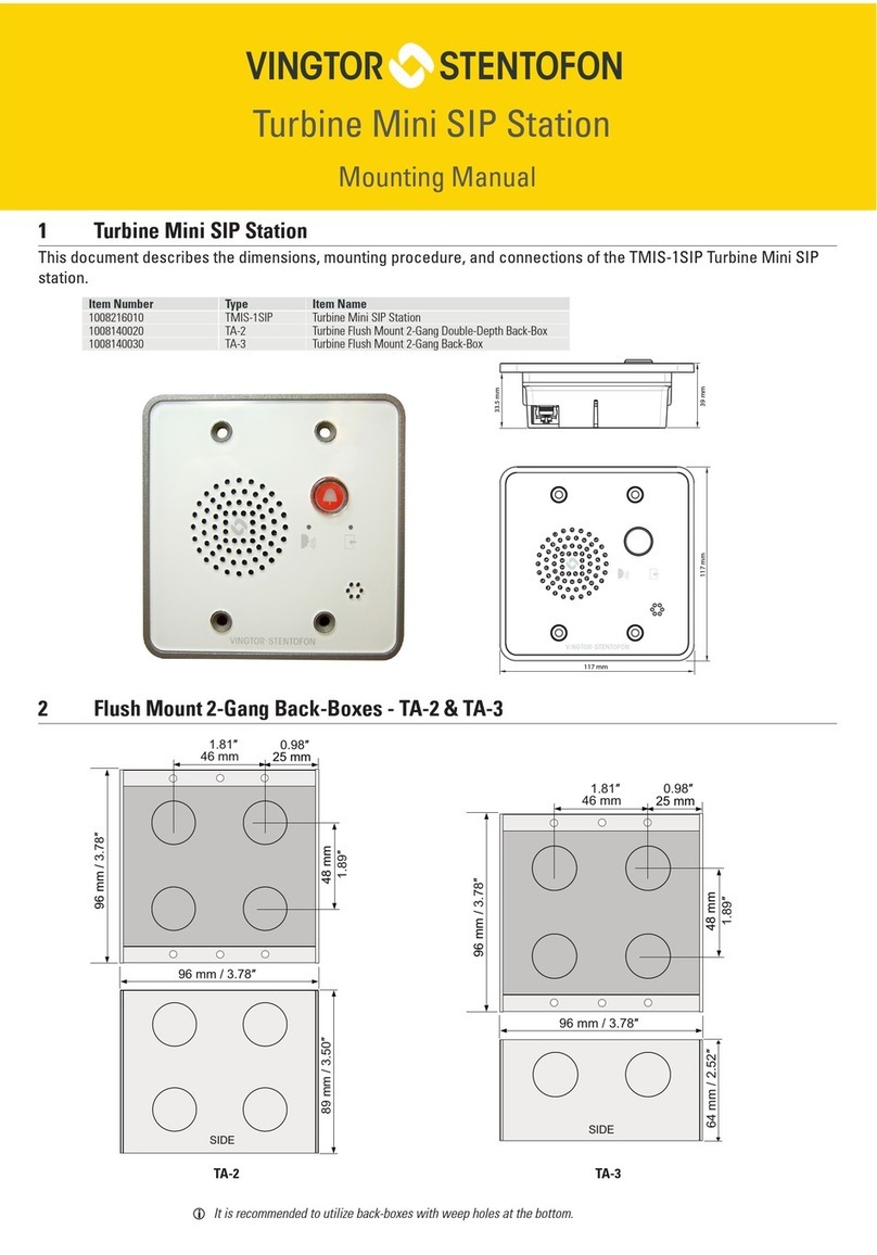
A100K11589 Turbine Mini Mounting Guide
Connection Guides
A100K11526 TAX-3 Handset for Turbine Ex Connection Guide
A100K11567 TA-23 Handset for Turbine Industrial Connection Guide
A100K11528 EMMAX-1H Compact Microphone for Turbine Ex Connection Guide
A100K11566 EMMAI-2H Compact Microphone for Turbine Industrial Connection Guide
A100K11565 EMMAI-1H Microphone for Turbine Industrial Connection Guide
A100K11525 TAX-2b Plugbox for Turbine Ex Connection Guide
A100K11564 TA-22b Plugbox for Turbine Industrial Connection Guide
General Manuals
A100K11499 Ex Turbine Intercoms & Exigo Access Panels Installation & Maintenance Procedures
A100K10805 AlphaCom XE Installation & Conguration
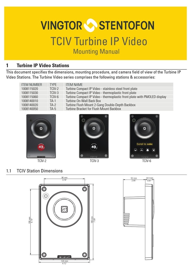
A100K11559 Turbine Video TCIV Conguration Manual

3
Turbine Station Conguration Guide
A100K11194
Contents
1 Turbine IP Intercoms ............................................................................................................................................ 5
1.1 Turbine Compact Intercoms .......................................................................................................................... 5
1.1.1 TKIS-2 Turbine Kit VoIP Intercom Module .................................................................................................. 6
1.2 Turbine Extended Intercoms ......................................................................................................................... 7
1.2.1 Industrial & Ex ............................................................................................................................................. 7
1.2.2 ECPIR-3P Indoor Intercom ....................................................................................................................... 12
1.2.3 TKIE-2 Turbine Extended Kit..................................................................................................................... 12
2 Intercom Connections........................................................................................................................................ 13
2.1 Connectors on Turbine Compact Intercoms................................................................................................ 13
2.1.1 Power Supply ............................................................................................................................................ 13
2.1.2 Network Connection.................................................................................................................................. 13
2.1.3 Input/Output Connections ......................................................................................................................... 14
2.2 Connectors on Turbine Extended................................................................................................................ 14
2.2.1 Power Supply ............................................................................................................................................ 14
2.2.2 Network Connection.................................................................................................................................. 15
2.2.3 Input/Output Connections ......................................................................................................................... 15
2.3 Connectors on Turbine Ex........................................................................................................................... 15
3 Accessories for Turbine Extended ................................................................................................................... 16
3.1 Connecting Turbine Extended Accessories................................................................................................. 16
3.1.1 Opening the TFIE/TFIX Enclosure ............................................................................................................ 16
3.1.2 Connection Terminal Block in Industrial Intercoms ................................................................................... 16
3.1.3 Connection Terminal Block in Ex Intercoms.............................................................................................. 17
3.2 TA-23/TAX-3 Handset for Turbine Extended ............................................................................................... 17
3.2.1 Connecting TA-23 Handset to TFIE-x Industrial Intercoms ...................................................................... 18
3.2.2 Connecting TAX-3 Handset to TFIX-x Ex Intercoms ................................................................................ 18
3.3 AK5850HS Headset for Turbine Extended with TA-22b/TAX-2b Plugbox ................................................... 18
3.3.1 Connecting TA-22b Plugbox to TFIE-x Industrial Intercoms .................................................................... 19
3.3.2 Connecting TAX-2b Plugbox to TFIX-x Ex Intercoms .............................................................................. 20
3.4 EMMAI-2H/EMMAX-1H Handheld Compact Microphone for Turbine Extended......................................... 20
3.4.1 Connecting EMMAI-2H Microphone to TFIE-x Industrial Intercoms ........................................................ 20
3.4.2 Connecting EMMAX-1H Microphone to TFIX-x Ex Intercoms ................................................................. 21
3.5 EBMDR-8 Expansion Module for ECPIR-3P............................................................................................... 21
3.5.1 Connecting EBMDR-8 Expansion Module to ECPIR-3P Intercom............................................................ 21
3.6 Turbine Relay Module - TA-10..................................................................................................................... 22
4 Starting Up the Station....................................................................................................................................... 23
5 ICX-AlphaComConguration............................................................................................................................ 24
5.1 Logging into the Station............................................................................................................................... 24
5.2 Main Settings............................................................................................................................................... 25
5.3 Audio Settings ............................................................................................................................................. 27
5.4 I/O Settings.................................................................................................................................................. 29
5.5 Address Book .............................................................................................................................................. 30
5.6 OLED Labels ............................................................................................................................................... 31
5.7 Sound Detection.......................................................................................................................................... 32
5.8 Time Settings............................................................................................................................................... 32
6 IC-EDGEConguration ..................................................................................................................................... 33
6.1 Logging into the Station............................................................................................................................... 33
6.2 Main Settings............................................................................................................................................... 34
6.3 Connect other Intercom Stations................................................................................................................. 35
6.4 Congure Edge Controller Directory ........................................................................................................... 35
6.5 Verify System Setup .................................................................................................................................... 36
6.6 Congure Call and Audio Settings............................................................................................................... 36
6.7 Modify IC-EDGE Device Proles................................................................................................................. 36
6.8 Group Call ................................................................................................................................................... 37
6.9 Mobile App Conguration ............................................................................................................................ 39
6.9.1 Add the Mobile App to the Edge Controller ............................................................................................... 39
6.9.2 Global Address List ................................................................................................................................... 40
6.9.3 Action Buttons ........................................................................................................................................... 41
6.10 Congure 3rd-party SIP Devices .................................................................................................................. 42
6.10.1 Install License ........................................................................................................................................... 42
6.10.2 Create SIP Account................................................................................................................................... 42
6.10.3 Congure SIP Phone ................................................................................................................................ 43
6.10.4 Verify Operation ........................................................................................................................................ 43
6.11 Advanced Conguration Mode .................................................................................................................... 43
6.12 Direct Access Key & Ringlist Settings ......................................................................................................... 45
6.12.1 Ringlist Settings ........................................................................................................................................ 46
4A100K11194
Turbine Station Conguration Guide
6.12.1.1 Forward Unattended Call ......................................................................................................................... 47
6.12.1.2 Forward Unattended Call with Loopback ................................................................................................. 48
6.12.1.3 Parallel Ringing - Forward Call if Unattended.......................................................................................... 49
6.13 Script Settings ............................................................................................................................................. 50
6.13.1 Script Upload............................................................................................................................................. 50
6.13.2 Script Conguration................................................................................................................................... 50
6.13.3 Script Events ............................................................................................................................................. 51
6.14 Audio Messaging......................................................................................................................................... 51
6.14.1 Uploading Audio Files ............................................................................................................................... 51
6.14.2 Play Message on DTMF Event ................................................................................................................. 52
6.14.3 Play Message On Call Event .................................................................................................................... 52
6.14.4 Play Message on Relay Event .................................................................................................................. 53
6.14.5 Routing of Audio Message ........................................................................................................................ 53
7 SIPConguration ............................................................................................................................................... 54
7.1 Logging into the Station............................................................................................................................... 54
7.2 Main Settings............................................................................................................................................... 55
7.3 Account/Call Settings .................................................................................................................................. 56
7.4 Audio Settings ............................................................................................................................................. 58
7.5 Direct Access Key & Ringlist Settings ......................................................................................................... 59
7.6 Relay/Output Settings ................................................................................................................................. 60
7.7 Time Settings............................................................................................................................................... 61
7.8 Audio Messages.......................................................................................................................................... 61
7.9 Advanced Conguration Mode .................................................................................................................... 62
7.10 I/O Settings.................................................................................................................................................. 64
8 Common Advanced Network Settings ............................................................................................................. 65
8.1 SNMP Settings ............................................................................................................................................ 65
8.2 Network Access Control .............................................................................................................................. 67
8.3 Firewall Settings .......................................................................................................................................... 69
9 Station Software Upgrade.................................................................................................................................. 70
9.1 Prerequisites ............................................................................................................................................... 70
9.2 Upgrade via Station Web Interface.............................................................................................................. 70
10 Station Indication LEDs ..................................................................................................................................... 72
10.1 LEDs on Front Plate .................................................................................................................................... 72
10.1.1 Compact Stations...................................................................................................................................... 72
10.1.2 ECPIR-3P, Industrial & Ex Stations........................................................................................................... 72
10.2 Status LEDs on PCB ................................................................................................................................... 72
10.3 Ethernet Activity & Speed LEDs .................................................................................................................. 72
11 Restoring Factory Defaults................................................................................................................................ 73
11.1 Reset to Factory Default Settings with Activated DHCP.............................................................................. 73
11.2 Reset to Factory Default Settings with Static IP.......................................................................................... 73
A: Compact Board Connectors.............................................................................................................................. 74
A.1 PCB - Front ................................................................................................................................................. 74
A.2 Input Connectors ......................................................................................................................................... 75
A.3 Output Connectors + 1 Relay...................................................................................................................... 75
A.4 Output Connectors + MRBD Relay Board................................................................................................... 76
A.5 PCB - Rear .................................................................................................................................................. 76
A.6 Front Board - Front...................................................................................................................................... 77
A.7 Front Board - Rear ...................................................................................................................................... 77
B: Extended Board Connectors............................................................................................................................. 78
B.1 PCB - Front ................................................................................................................................................. 78
B.2 Input Connectors ......................................................................................................................................... 78

5
Turbine Station Conguration Guide
A100K11194
1 Turbine IP Intercoms
1.1 Turbine Compact Intercoms
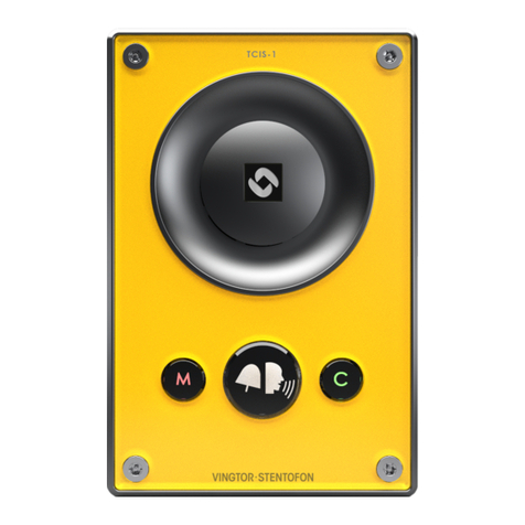
TCIS-1
Thermoplastic Frontplate with Single Call
Button plus Push-To-Talk & Cancel
TCIS-2/TCIV-2/TCIA-2
Stainless Steel Frontplate with Single Call Button
TCIS-3/TCIV-3
Thermoplastic Frontplate with Single Call
Button
TCIS-4
Thermoplastic Frontplate with Single Call
Button and PMOLED Display
TCIS-5/TCIV-5
Thermoplastic Frontplate with Two Call Buttons
and PMOLED Display
TCIS-6/TCIV-6
Thermoplastic Frontplate with Call & Scrolling
Buttons and PMOLED Display
TMIS-1 Turbine Mini
Thermoplastic Frontplate with Single Call Button
TMIS-2 Turbine Mini
Stainless Steel Frontplate with Single Call Button

6A100K11194
Turbine Station Conguration Guide
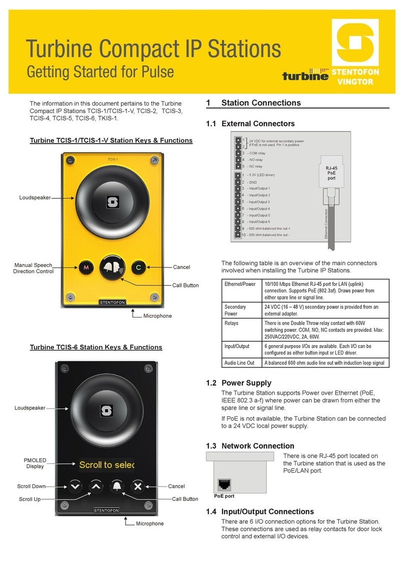
Figure 1 Turbine TCIS-1 Station Keys & Functions
Figure 2 Turbine TCIS-6 Station Keys & Functions
1.1.1 TKIS-2 Turbine Kit VoIP Intercom Module
Speaker
Cancel
Microphone
Manual Speech
Direction Control
Call Button
Speaker
Cancel
Microphone
Call Button
Scroll Up
Scroll Down
PMOLED
Display

7
Turbine Station Conguration Guide
A100K11194
1.2 Turbine Extended Intercoms
1.2.1 Industrial & Ex
TFIE-1
Industrial Intercom with Full Keypad
TFIE-2
Industrial Intercom with 6 Programmable Keys
TFIE-6
Industrial Intercom with Scrolling Unit &
PMOLED Display
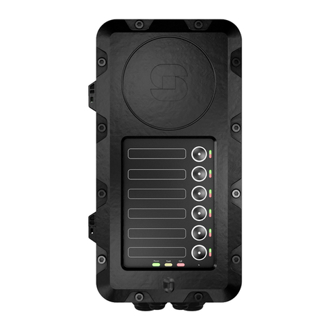
TFIX-1
Ex Intercom with Full Keypad
TFIX-2
Ex Intercom with 6
Programmable Keys
TFIX-3
Ex Intercom with Single Call Button
plus Push-To-Talk & Cancel
TFIX-4
Ex Intercom with Full Keypad
(requires External Speaker)

8A100K11194
Turbine Station Conguration Guide
+
Fault
LED
Call
LED
Power
LED
Figure 3 Turbine TFIE-1/TFIX-1/TFIX-4 Station Keys & Functions

9
Turbine Station Conguration Guide
A100K11194
+
Fault
LED
Call
LED
Power
LED
Figure 4 Turbine TFIE-2/TFIX-2 Station Keys & Functions

10 A100K11194
Turbine Station Conguration Guide
+
Dialing
Keys
Manual
Speech
Direction
Control
Speaker
Cancel/Private/Open
Direct Access Keys
Fault
LED
Call
LED
Power
LED
Microphone
PMOLED
Display
Scroll Up
Scroll Down
Confirm
Menu
Figure 5 Turbine TFIE-6 Station Keys & Functions

11
Turbine Station Conguration Guide
A100K11194
Figure 6 TFIX-3 Station Keys & Functions
Fault
LED
Call
LED
Power
LED

12 A100K11194
Turbine Station Conguration Guide
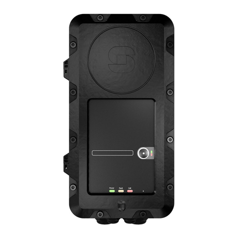
1.2.2 ECPIR-3P Indoor Intercom
The ECPIR-3P is an Indoor Intercom with 3 programmable keys
Speaker
PTT Key
Volume Control
Dimmer
+
Fault
LED
Call
LED
Power
LED
Figure 7 ECPIR-3P Intercom Keys & Functions
1.2.3 TKIE-2 Turbine Extended Kit
The TKIE-2 is the extended version of the Turbine Kit range.
Figure 8 TKIE-2 Connectors & Functions

13
Turbine Station Conguration Guide
A100K11194
2 Intercom Connections
2.1 Connectors on Turbine Compact Intercoms
The Turbine Compact Board is used by the following stations: TCIS-1, TCIS-2, TCIS-3, TCIS-4,
TCIS-5, TCIS-6, TKIS-2, TMIS-1.
LNote that the TCIA-2 has a dierent set of connectors
See Appendix A: Compact Board Connectors for further information.
Figure 9 Connectors on Turbine Compact Station
The following table is an overview of the main connectors involved when installing the Turbine IP
Stations.
Ethernet / Power 10/100 Mbps Ethernet RJ-45 port for LAN (uplink) connection. Supports PoE
(802.3af). Draws power from either spare line or signal line.
Secondary Power 24 VDC (16 – 48 V) secondary power is provided from an external adapter.
Relays There is one Double Throw relay contact with 60W switching power. COM, NO,
NC contacts are provided. Max: 250VAC/220VDC, 2A, 60W.
Input/Output 6 general purpose I/Os are available. Each I/O can be congured as either
button input or LED driver.
Audio Line Out A balanced 600 ohm audio line out with induction loop signal
2.1.1 Power Supply
The Turbine Compact Station supports Power over Ethernet (PoE, IEEE 802.3 a-f) where power can
be drawn from either the spare line or signal line. If PoE is not available, the Turbine Compact Station
can be connected to a 24 VDC local power supply.
2.1.2 Network Connection
There is one RJ-45 port located on the Turbine Compact station that is
used for PoE/LAN Ethernet connection.
PoE port
1
5
4
3
2
1
6
10
5
4
3
2
9
8
7
RJ-45
PoE
port
24 VDC for external secondary power
if PoE is not used. Pin 1 is positive.
- 5.3V (LED driver)
- GND
- Input/Output 5
- COM relay
- NC relay
- NO relay
- Input/Output 1
- Input/Output 2
- Input/Output 3
- Input/Output 6
- 600 ohm balanced line out +
- 600 ohm balanced line out -
- Input/Output 4
Ethernet Connection

14 A100K11194
Turbine Station Conguration Guide
2.1.3 Input/Output Connections
There are 6 I/O connection options for the Turbine Compact Station.
These connections can be used to interface with external I/O devices. The connections are typically
used as digital input (eg. form a closing contact), digital output (5V), or LED driving (20mA max)
for connecting sensors, indicators or integration to other systems. See Appendix A for further
information.
2.2 Connectors on Turbine Extended
The Turbine Extended board is used in the following stations: TFIE-1, TFIE-2, ECPIR-3P, TKIE-1,
TFIX-1, TFIX-2, TFIX-3, TFIX-4.
See Appendix B: Extended Board Connectors for further information.
Figure 10 Connectors on Turbine Industrial Station
LAll connections are made on the main board inside the enclosure of the Turbine Industrial station.
2.2.1 Power Supply
The Turbine Industrial Station supports Power over Ethernet (PoE, IEEE 802.3
a-f) where power can be drawn from either the spare line or signal line.
If PoE in not available, the Turbine Industrial Station can be powered from a 24-
48 VDC local power supply.
LIf used together with PoE the station can be powered by 24 VDC as a local power
backup.
LIf connected to two PoE-capable switches, only one of the ports will negotiate
PoE; hence this is not a good solution for power redundancy (switch failure might
lead to a reboot). Instead a “dumb” PoE injector (spare-pair power) should be used
for the two Ethernet ports or a local 24 VDC local power backup.

15
Turbine Station Conguration Guide
A100K11194
2.2.2 Network Connection
There are two RJ-45 ports located on the Turbine Industrial station, either of which can be used for a
single PoE/LAN Ethernet connection.
2.2.3 Input/Output Connections
There are 6 I/O connection options for the Turbine Industrial Station.
These connections are used as digital input (eg. form a closing contact), digital output (5V), or LED
driving (20mA max) for connecting sensors, indicators or integration to other systems. See Appendix
B: Extended Board Connectors for further information.
2.3 Connectors on Turbine Ex
Figure 11 Connectors on Turbine Ex Station
LAll connections are made on the main board inside the enclosure of the Turbine Ex station.
Procedures for connecting power supply, LAN network and Inputs/Outputs are described in the
manual A100K11499 Ex Turbine Intercoms & Exigo Access Panels Installation & Maintenance
Procedures.
+-+-
+ Integrated Mic +
- Integrated Mic -
S Integrated Mic shield
1 Audio accessory speaker +
2 Audio accessory speaker -
3 Audio accessory microphone +
4 Audio accessory microphone -
5 Audio accessory Push To Talk (PTT)
6 Audio accessory Hook
7 Audio accessory Ground
8 Integrated loudspeaker +
9 Integrated loudspeaker -
Connectors
for Flowire
24V DC
Connector for
Front board

16 A100K11194
Turbine Station Conguration Guide
3 Accessories for Turbine Extended
3.1 Connecting Turbine Extended Accessories
Accesories such as the handset, plugbox for the headset, and handheld microphones are connected
to the connection terminal block J8 on the main board inside the station enclosure. Follow the
instructions for opening the enclosure in the section below.
3.1.1 Opening the TFIE/TFIX Enclosure
3.1.2 Connection Terminal Block in Industrial Intercoms
Accessories are connected to the 9-pin connection terminal block J8 on the main board in the
Turbine Industrial enclosure.
1 Open the enclosure by
loosening the 2 screws that
secure the front frame to
the on-wall box
2Open the enclosure by pulling
the front frame out 5 mm, keep-
ing it parallel to the on-wall box.
This is necessary to get clearing
for the hinges.
3 Then pull the right side of the front
frame to fully open the enclosure.
Make sure to not open the enclosure
so far that cables between the front
and back parts are pulled tight.

17
Turbine Station Conguration Guide
A100K11194
3.1.3 Connection Terminal Block in Ex Intercoms
Accessories are connected to the 12-screw connection terminal block in the Turbine Ex enclosure.
+-+-
+ Integrated Mic +
- Integrated Mic -
S Integrated Mic shield
1 Audio accessory speaker +
2 Audio accessory speaker -
3 Audio accessory microphone +
4 Audio accessory microphone -
5 Audio accessory Push To Talk (PTT)
6 Audio accessory Hook
7 Audio accessory Ground
8 Integrated loudspeaker +
9 Integrated loudspeaker -
Connectors
for Flowire
24V DC
Connector for
Front board
3.2 TA-23/TAX-3 Handset for Turbine Extended
The handset comes with a Push-To-Talk (PTT) button and 3.5-meter long cable.
● TA-23: used with Turbine Industrial intercoms
● TAX-3: used with Turbine Ex intercoms
Figure 12 TA-23/TAX-3 Handset
PTT Button
Speaker
Microphone

18 A100K11194
Turbine Station Conguration Guide
3.2.1 Connecting TA-23 Handset to TFIE-x Industrial Intercoms
Plug the IDC connectors on the Handset cable into the J8 terminal block according to the pin
conguration below.
1
65432
987
Black Yellow White Blue Green
TA-23 Handset Connection
on 9-Pin Terminal J8
Red
PTT-
PTT+
Mic+
Mic-
LS+
LS-
3.2.2 Connecting TAX-3 Handset to TFIX-x Ex Intercoms
Connect the wire ferrules on the Handset cable to the terminal block according to the pin
conguration below.
Blue
3.3 AK5850HS Headset for Turbine Extended with TA-22b/TAX-2b
Plugbox
The Headset comes with a boom microphone, curled cord and plug.
The Plugbox comes with a PTT button and 10-meter long cable.
● TA-22b: used with Turbine Industrial Intercoms
● TAX-2b: used with Turbine Ex Intercoms

19
Turbine Station Conguration Guide
A100K11194
Figure 13 AK5850HS Headset with TA-22b/TAX-2b Plugbox
3.3.1 Connecting TA-22b Plugbox to TFIE-x Industrial Intercoms
Plug the IDC connectors on the Plugbox cable into the J8 terminal block according to the pin
conguration below.
1
65432
987
Yellow Green Pink WhiteBlack
TA-22b Plugbox Connection
on 9-Pin Terminal J8
Brown
PTT-
PTT+
Mic+
Mic-
LS+
LS-
AK5850HS
TA-22b / TAX-2b
PTT Button
Nexus Plug
Jack

20 A100K11194
Turbine Station Conguration Guide
3.3.2 Connecting TAX-2b Plugbox to TFIX-x Ex Intercoms
Connect the wire ferrules on the Plugbox cable to the terminal block according to the pin
conguration below. Note that the black (shield) wire is labeled MIC- and the black (main shield) wire
is labeled GND.
3.4 EMMAI-2H/EMMAX-1H Handheld Compact Microphone for Turbine
Extended
The Compact Microphone comes with a Push-To-Talk (PTT) button and 3-meter long cable.
● EMMAI-2H: used with Turbine Industrial intercoms
● EMMAX-1H: used with Turbine Ex intercoms
3.4.1 Connecting EMMAI-2H Microphone to TFIE-x Industrial Intercoms
Plug the IDC connectors on the Compact Microphone cable into the J8 terminal block according to
the pin conguration below.
1
65432
987
Yellow Red Blue
EMMAI-2H Microphone Connection
on 9-Pin Terminal J8
Black
PTT-
PTT+
Mic+
Mic-
(shield)
Black (main shield)Chassis Ground
MIC -
GND
This manual suits for next models
22
Table of contents
Other Vingtor Stentofon Intercom System manuals

Vingtor Stentofon
Vingtor Stentofon TCIS-1 Guide

Vingtor Stentofon
Vingtor Stentofon TCIV-2 Guide

Vingtor Stentofon
Vingtor Stentofon TCIS-1 User manual

Vingtor Stentofon
Vingtor Stentofon Turbine TMIS-1 Installation instructions manual

Vingtor Stentofon
Vingtor Stentofon ECPIR-3P User manual

Vingtor Stentofon
Vingtor Stentofon TCIS-1SIP Guide

Vingtor Stentofon
Vingtor Stentofon Turbine Compact Analog TCAS Series Guide

Vingtor Stentofon
Vingtor Stentofon Exigo Ex EAPFX-1 User manual

Vingtor Stentofon
Vingtor Stentofon Exigo Ex EAPFX-1 Guide

Vingtor Stentofon
Vingtor Stentofon ITSV-1 User manual