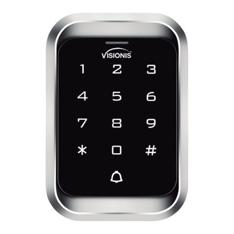
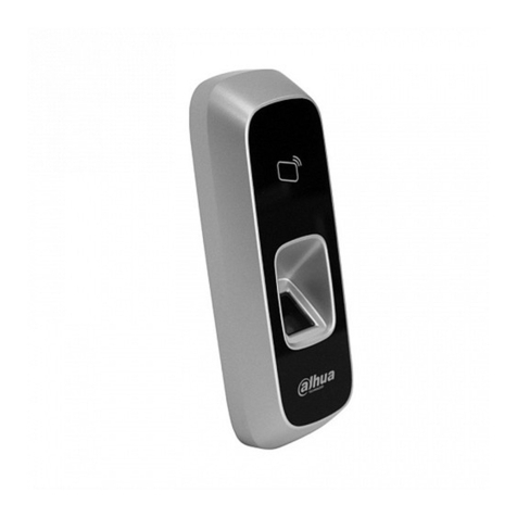
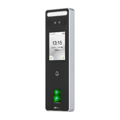
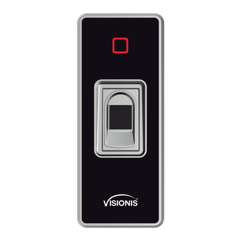
Visionis VIS-3000 User manual

User Manual
1. Introduction, Feat ur es a nd S pecifications
1.1 I ntrod uctio n
The Vsio ni s VIS-30 00 Stan d alone a ccess c ontro l Reade r/Key pad Car d or Key ta g reading a nd k eyp ad
ope ration fu nc tions , loc k, al arm, rin g bell, exit b ut ton a nd the Alarm m ag ne tic c ontac t switch on t he
doo r.
The a ccess h ost sup ports 1 25KHz E M, HID cards .
It co ntrol s 1 door, and s uppor ts up to 20 00 u sers in t ot al, each u ser have on e ca rd an d one PIN .
The a ccess c ontro l unit su pport s 1 maste r code, one ma na ger add c ard, one man ag er dele te c ard,
1 ant i-dur ess car d and 1 ant i-dur ess PIN , pro vidin g users w ith eas y opera tion and sa fe g uaran tee.
1.2 F eatur es
> Alumin um a lloy ca se, wat erp roof, weathe r Proof , con firms t o IP65 St andar d touch p anel
> Bui lt-in 1 25KHz ( EM, HID card ) an d 13.56 MHz(I C, CPU card, ISO1 4443A ) reade r touch p anel
> The back l ig ht can be s et t o Nor mal ON, Norm al O FF or Auto .
> With doo r be ll func ti on, buil d- in or ext er nal d oor bel l optio nal.
> Mul ti-fu nctio n, operati ng as sla ve reader, si ngle do or, anti- pa ss ba ck func tion, etc, suit ab le fo r
Dif feren t type of I nstal lations .
1.3 S pecif ication s:
Ope rating vo lt age ran ge: DC12-2 4V
Idl e input c urren t: ≤35mA
Max p roxim ity car d read ra nge: EM&HI D ca rd: 3-6c m IC&CP U card: 2-6c m
Fre quenc y: 125KH z an d 13.56 MH z
Car d trans mit for mat: Wie gand 26 -3 7
Key pad tra nsmit f ormat: 4-6 d igits k ey pres s to outp ut card n umber f ormat, 4 bits or 8 b its data.
Acc ess con trol un it dime nsion s (Heig ht×Wi dth×D epth) 1 25×83 ×21.7 mm Or 4.9 2x3.2 7x0.8 5
Inc he s
Ope rating te mp eratu re rang e: -40~60° C or -4 0° F ~140 °F (EM& HID car d), -20~60° C or
-4° F ~140°F I C or CPU
+
+12 V
1N4 00 4
NO GN D
COM
NC
LOC K A +
+12 V
1N4 00 4 NO GN D
COM
NC
LOC K B
Wir ing of el ectro nic loc k
Con nect CO M and GND , connec t two end s of elec troni c lock wi th +12V and NO or N C, c omple te
the c ircui t.
Type A elec troni c lock: Fa il S ecu re lock ( Unloc k when po wer on), such as E lectr onic Co ntrol ling Lo ck,
sma rt lock .etc.
Type B e le ctron ic l ock : Fai l Safe lo ck ( Unloc k wh en po wer off), such a s Elect romagne ti c Lock,
Ele ctron ic Bolt L ock, etc.
1N4 004 Dio de: preven t hi gh volt ag e to two en ds o f the ele ct ron ic lock w hile th e conta ct of rel ay
dis conne ct .Wit hout di ode, there w il l be high v oltage pu ls e inter feren ce to cir cuits a nd the li fe time o f
the r elay wi ll be gre atly redu ce d.
2. Installation and Wi ri ng D ia gr am
Wir ing Dia gram
VIS -3000 S ingle d oor(D C power sup pl y )
BEL L_ A
BEL L_ B
+12 V
GND
D0
D1
D_i n( LED)
OPE N( BZ)
NO
COM
NC
ALA RM -
Doo rBe ll
Red Bla ck
Bla ck G reen Wh it eRed B ro wn Yel lo w bl ue Purp le O range G ra y
Ala rm
Doo rContact
Exi tBu tton
Pin k
Lig ht
gre en
Reader
Standalon e Ac ce ss C on tr ol
Gre en W hite
Loc kB
Loc kA
DC 12 V
Pow er
BEL L_A
BEL L_B
Pri ncipl e of Door B ell Con necto r
Eac h press o f door be ll butt on, contac t of r elay in B ELL_A a nd BELL _B will
clo se cont ac t for 200 mS t hen r eleas e.
+12 V +12 V
ALA RM- P ri nci ple of Al arm Con necto r
The f ield- effec t tube wi ll be con ducte d when al arm is ac tivated ; It w ill be no t
con ducte d when al arm is re moved
+12 V +12 V
NO
NC
COM
GND
Pri ncipl e of Elec troni c Lock
The r elay wi ll clos e conta ct t o unloc k the loc k and wil l relea se afte r unloc king
COM : common, relay contact
NC: n ormal c lose, no rmall y keep cl osed to C OM
NO: nor mal ope n, normall y ke ep open ed to COM
VIS -3000 S ingle d oor (Sp ecial a ccess c ontro l power sup pl y )
BEL L_ A
BEL L_ B
+12 V
GND
D0
D1
D_i n( LED)
OPE N( BZ)
NO
COM
NC
ALA RM -
PUS H
+12 V
GND
NO
COM
NC
50m S
Doo r
Bel l
Gre en
Whi te
Red
Bla ck
Bla ck
Gre en
Whi te
Red
Bro wn
Yell ow
blu e
Pur pl e
Ora ng e
Gra y
Ala rm
Doo rContact
Exi tBu tton
Loc kB
Loc kA
Pin k
Lig ht gree n
Rea de r
Access Cont ro l
Pow er S upply
Standalon e Ac ce ss C on tr ol
Factory
default 0(50mS)
PUS H
4.7 D oor Bel l
Pre ss the do or bell b utton o n the acc ess con trol un it, the buzz er w ill sou nd ring b ack ton e, at the s ame
tim e, the I box's b ui lt-in d oo r bel l or the ou ter doo r bell wi ll ring .
Rem ark: Wh en the wo rk mode i s set in Au to Mode ( Facto ry D efa ul t Mod e), there wi ll b e no ring
bac k tone wi thout t he I Box.
5.1 Ant i Tamper Alarm
When the acc ess contr ol unit is dis ass embled il legally, the acces s control unit's buzzer an d the external
alarm will oper ate .
5. Alarm
5.2 Do or Sta tus S witch
When connect wi th doo r status sw itc h, if the do or is op ened ille gal, the access contro l unit's bu zzer and
the ex ternal al arm wi ll operate.
5.3 Ant i-dures s alarm
When read zo ne 1 dur ess ca rd / inp ut 8digit s dure ss PIN OR zone 2 dures s card / input 8 digits du ress PIN,
then press #, the cor respond ing lock wi ll ope n, at the same ti me, the exter nal alarm w ill op era te, but t he
access contro l unit's bu zzer will no t operate.
5.4 To remov e the al arm
Read valid card or input mast er cod e can re move the alarm. If th ere is no operation, the alarm will remov e
automatica lly af ter 1 mi nute.
Keypad access c ontrol, po wer of f, keep pressing * and pow er on, th e logo will tu rn in orange after 1
second, releas e it unt il hea rin g two sh ot bee p , then hearin g a long beep, enter no rmal mode , reset to
factory defa ult se tting is succes sfu lly.
Touch pa nel ac cess cont rol (V IS- 3000) ,po wer of f, pow er on, the logo will turn in orange after 1 secon d,
press * with in 1 sec ond, relea se it until he aring two shot beep, the n hear ing a lo ng bee p, enter
normal mode, res et to factor y def aul t sett ing is successfull y.
Remark: Reset to facto ry de fault, the us ers ' info rma tion is still ret ained.
7. To Res et t o Factory Defau lt
3.1 Add us er card (s)(I n dual do or mode , use rs can be o nly add ed to zon e 1)
Rea d manager a dd c ard Rea d Userc ard Rea d manager a dd c ard
Car ds can be a dded co ntinu ously.
3.2 D elete u ser car d(s)
Read m anager de le te card R ead Use r card Re ad mana ger delet e ca rd
Car ds can be d elete d conti nuous ly.
3 . Manager Cards Operat io n
4. User Operation
4.1 To un lock th e lock by o ne card : Rea d valid c ard onc e, the lock wi ll b e unloc ked.
4.2 To un lock th e lock fo r card an d PIN use rs
Rea d valid c ard onc e Input 4 -6 digi ts PIN # , the loc k wi ll be unl ocked .
4.3 To un lock th e lock fo r card or P IN user s
Rea d valid c ard Or In put 4-6 d igits P IN # , the lock wi ll b e unloc ked
4.4 To un lock th e lock fo r multi c ards: Read 2 -1 0pc s valid c ards (t ime int erva l can n ot exce ed 5s), the
loc k will be u nlock ed.
Pre condi tion: Set th e do or entr y by card onl y, and s et “2-10 ”for op ening t he door b y multi c ards
4.5 Tog gle Mod e
In no rmal mo de, Every time a v al id card /t ag read o r PI N input , the r eplay w il l opera te, for the pr e- set
rep lay pul se time .
Eve ry time a val id card /tag read o r PI N input i n Toggl e mode, the re la y chang es s tate, whic h wi ll no t
tur n back un til rea d card/ tag or inpu t PI N again .
4.6 To change t he P IN of a PIN u se r
Rea d card In put old P IN # Inpu t new PIN # I nput ne w PIN #
Or
Use r ID numb er Inpu t old PIN # I nput ne w PIN # Inp ut new PI N #
Rem ark:
For u sers wi th out car d, mu st get ID n um ber and i ni tia l PIN fro m the mas ter. For Zone 1, the fi rs t dig it of
PIN m ust be “1”, for Zon e 2, th e first d ig it of PIN m ust be “2” For th e card us er s with PI N “12 34”, must
use R eadin g card to c hange t he PIN fo r the fir st time .
*
*
8. Sound and Light Indic at io n
Ope ration St at us
Standby
Pre ss Key
Rea d Card
Unl ock the l ock
Ope ration Su cc essfu l
Ope ration Fa ile d
PIN I nputt ing
Car d & PIN Rea ding
Mul ti Card R eadin g
1 Men u
2 Men u
Log o Color
Whi te
Gre en
Slo w Flash Red
Gre en
Gre en
Slo w Flash Red
Slo w Flash Red
Slo w Flash Red
Slo w Flash Ora ng e
Buz ze r
Sho rt Ring
Lon g Ring
Lon g Ring
Lon g Ring
3 Sho rt Ring
Und er Sett ing
Man ager Card R ea ding
Man ager Card E xi t
Ala rm
Rin g-bac k Tone
Ora ng e
Whi te
Qui ck Shin e in Red
Ora ng e 2 Short R in g
Lon g Ring
Ala rm
Din g- Dong
st
nd
Log o LED Lig ht indi cation Rem ar ks
Fac tory defa ul t :
888 88 8
Fun ct ions
To ent er the
pro gramm ing mod e
Whi te logo
* 6-8 d igits M aster c ode #
Red l ogo LED f lash
Ent er Mast er Op erati on Mode . It wil l retur n to no rmal mo de if t her e is no right Ma ste r PIN inp ut in 5
sec onds. Aft er inpu t of ri ght master P IN, it wil l als o ret ur n to no rma l mode if t her e is no valid op erati on
in 30 s eco nds. Pre ss “#” to con fir m the input nu mbe r, retu rn to previo us me nu by press “*” , the logo
lig ht will indi ca te th e ope ra tio n mode.
Not e that to unde rtake the fo llowi ng pr ogram min g, th e mas ter user mus t be lo gged in
9. Master Setting
03
To preve nt con secutive enter of an in valid mas ter co de, user password, or ant i-d uress or invali d card,
this function w ill be activated after 10 times consecuti ve err ors input . There ar e 3 mode avail abl e:
No key pad lo cko ut or alarm, keypad lock ed for 10 minu tes, alarm fo r 1-3 mi nut es.
6. Keypad lockout or ala rm
9.2 Adva nc ed oper at ion:
Rem ar ksFun ct ions
Red
Flash Ora ng e
Adv anced A ppl ication
Orange
Flash
Remark:
① Every time a valid card/tag read or PIN input in in Toggle mode, the relay changes state, which will not turn
back until read card/tag or input PIN again.
②The door will open only when read the valid card quantity up to the quantity set. It is only for Card Only mode.
③ The card number must be consecutive, Card quantity is between 1-2000.
④ After unlocking, enter the normal working state.
⑤ After closed the alarm, anti tamper, anti-duress and door magnetic alarm are invalid.
⑥ Refers to static state, normal indication according to operation.
⑦ Enter the administrator password correctly, the buzzer alarm in the normal phonation.
⑧ Each key press or read card, keypad backlight will light 30S delay after the close, in close state , the first key
is just to start the keyboard light, no any function.
⑨ 10 times consecutive errors including: enter an invalid master code, user password, or anti-duress or invalid
card.
10. Vari ou s Working Modes Applica ti on
The device has 3 working modes:
1. Wiegand Reader
2. Standalone for single door (Factory default setting)
3. Anti-pass back for single door
Through Wiegand data lines , can make the device and external card reader are connected together, to realize
of various functions.
Card number and PIN etc information will store in the device.
The external reader only read card or as a device for input PIN, you can connect with a numbers of readers , but
function all same.
Access
Host
External Read er
(Inside Door)
(Outside Door)
Access
Host
(Outside Door)
Standalone for single door Anti-pass back for single door
10. 1 Wie gand Re ader Mo de
VIS-3000 Reader Wiring Dragram
BELL_A
BELL_B
+12 V
GND
D0
D1
D_i n( LED)
OPE N( BZ)
NO
COM
NC
ALA RM -
Doo rBe ll
Bla ck G reen Wh it eRed B ro wn Yel lo w bl ue Purp le O range G ra y
Ala rm
Pin k
Lig ht
green
CND D 0 D1+12 V LED B Z
Common Acce ss C on tr ol
Standalon e Ac ce ss C on tr ol ( Reader Mode)
In this mode, the access host works as reader, it can be done below settings.
Rem ar ksFun ct ions
Red
Flas h Ora ng e
Orange
Flash
Adm inist rator Set ti ng
Remarks
Fac tory defa ul t :8888 88
Fun ct ions
Ent er prog rammi ng mode
Whi te
* 6-8 d igi ts Mast er co de #
Red f lash
Rea der Set ting
6~8 digits new master
code # Repeat 6~8
digits new master code
#
Facto ry def ault : 888888 Chan ge the master
code
0
10.3 Anti-passback for Single Door
> In this mode, access host install outside is for entering door, external reader inside for exiting door, they build
up a single door anti-passback system, access host is the anti-passback master unit.
> Read valid card or input PIN on access host, door will open; read valid card or input PIN on external reader,
door will open.
> When input duress PIN/Card, the door will open, at the same time, the external alarm operates
> When input duress PIN/Card on external reader, the door will open, at the same time, the external alarm
operates.
> Open type forced Card Only, the user PIN is invalid.
> The users can only enter door when read valid card on access host, and exit from the inside external reader,
If without the entering record from access host, the users can not exit from the inside reader, also the users
can't enter in twice without the first exit record.
Cannot enter
Administrator
setting mode
Forget master code
For o ther is su es beyo nd abov e, welcome t o co ntact o ur t ech nicia ns for mo re deta ils.
Reset to Factory Default, default master code is 888888,
need to reset conditions and specifications, but users'
information is still retained
Fault Phenomenon Fault Cause
Reading distance
is too close
1. Card problem
2. Switch power supply
interferences card reading
Set user PIN failed
1. Wrong way of PIN setting
2. Setting PIN under card
reading mode
Can’t open door
after inputting
user's PIN
Use 1234 as user's PIN
Alarm under
normal situation
Light leaking when install
access host
No reaction when
reading card not on standby status
Reason & Solution
1. Please use original made card
2. Wiring power supply and access host shell to ground
wire
1. In mode of two Doors 1,the 1st digit of PIN must be 1.
Two doors 2, the 1st digit of PIN must be 2.
2. User PIN cannot be 1234
3. User PIN only can be 4~6 digits
1234 is the initial value, can't be used to open doors,
unless after resetting them to other 4~6 digits
Leaning on wall closely when install access host
Exit by pressing * until logo light turns to white
1. Set the keypad light to always On or automatic mode
2. Under automatic mode, keypad light will on when
people approaching
Keypad light off Set keypad light mode
improperly
11. Simple Trou bl eshooting
Facto ry def ault setting: 0
0-15 , # To set facility code
Facto ry def ault setting:2 6
4-6 dig is key pr ess sends car d number
Each ke y press sends 4 bit outpu t data
(Fact ory de fault setting)
Each ke y press sends 8 bit outpu t data
Clos e Alarm
Alam ti me is 0-3 minutes for opt ion
No door bell fun ctio n
Buil t-in door bell- ON (Fac tory defau lt
setti ng)
Exte rnal door bell-ON
Buil t-in & external door bell - ON
To set Wiegand format
To set keypa d
tran smis sion forma t
To set Alarm
To set door bell
func tion
26-3 7, #
0, #
2, #
1, #
2
3
0
0, #
1-3, #
4
0, #
1, #
2, #
3, #
5
7
When LED level is low, logo light will turn into Green, after 30 seconds or LED level rising, Logo light will back to
normal.
When BZ level is low, the Buzzer will beep, after 30 seconds or BZ level rising, the Buzzer will back to normal.
When the access host worked as reader, both card number and keypad transmits in Wiegand format, the output
data are shown by the Low Level of D0 & D1 cable:
D0: Low level means 0, green cable
D1: Low Level means 1, white cable
The Pulse Width of Low level is 40uS, Bit period is 2mS.
The digit of Car number can be set to 26~27Bit, should be matched with the controller. (Factory default is 26Bit)
Wiegand 26 card reader, HID card can output Wiegand 26~37 automatically, other cards are output Wiegand 26
compulsively.
Wiegand 27~37 card reader, all cards are forced output Wiegand 27~37.
Keypad transmission can be set in the following 3 modes
Disa ble
Enab le(Fa ctory default se ttin g)
OFF- The device will be in sil ence
exce pt enter the pro gram ming mode
ON-T he device will give the voice when
pres s the keys (Factory default setti ng)
Disa ble keypad backli ght
Enab le keypad backlig ht (Factory
defa ult setting)
To set logo LED light
To set keypa d tone
ON or OFF
To set keypa d
back ligh t
0, #
1, #
0, #
1, #
0, #
1, #
2
3
1
8
Auto matic mode
Norm ally it is off(s leep ing mode) but
wake up with hum an approac h
Disa ble anti tamper alar m ( Factor y
defa ult setting )
Enab le anti tamper alarm
To set anti tamper
alar m
0, #
1, #
2, #
4
To set keypa d
back ligh t
Model 0: The Reader will transmit the PIN data when it receives the last key (#) press after PIN code
Format: Decimal card number with 10-digit , Facility Code(1st ~ 4th digit)+ PIN Code (5th ~ 10th digit)
(Facility code is any digits between 0~15, PIN code is 4~6 digits)
Example: Facility code:15
PIN code: 2999
Press 2999 #, then output format will be: 0015002999
PIN code: 999999
Press 999999#, then output format will be 0015999999
9.1 B asic Op eration
( Factory default setting: 26 )
4-6 digis key press sends card number
Each key press sends 4 bit output data
( Factory default )
Each key press sends 8 bit output data
To set Wiegand format
To set keypad
transmission format
2
3
7
26-37, #
0, #
1, #
2, #
Close Alarm⑤
Alarm time is 0-3 minutes for option
( Factory default 1 minute )
To set Alarm
4
Ope ional S ettin g
Indicator light OFF⑥
Indicator light ON ( Factory default )
Disable buzzer ⑦
Enable buzzer ( Factory default )
Disable keypad backlight
Enable keypad backlight ( Factory default )
Auto mode⑧
Disable anti tamper alarm ( Factory default )
Enable anti tamper alarm
No keypad lockout or alarm (Factory default)
In 10 minutes, if there's 10 times⑨invalid
card or wrong password, the device will lock
on for 10 minutes.
In 10 minutes, if there's 10 times invalid card
or wrong password, the device will alarm.
To set logo LED light
0, #
1-3, #
0, #
1, #
1
0, #
1, #
2
0, #
1, #
3
2, #
0, #
1, #
4
0, #
1, #
5
2, #
8
Read card Set add card To add card user
1
6
Set delete card
To set duress users
To delete card user
To set duress user
Read card
Read card
8 digits duress PIN,# To set duress PIN To set duress PIN
Automatic mode Factory default ( )
Set Zone 1as Auto-lock switch①
Factory default setting :1 To set open door by
multi cards②
Relay setting
The card number must be consecutive
Card quantity is between 1-2000
User ID number # card
number # card quantity #
To add a series cards
users. ③
0, #
1, #
1-10, #
Administrator open door 1 Exit automatic④
1
2
3
4
5
6
7
9
System Setting
Factory default setting: 0
Wiegand reader mode
Standalone for single door Factory default ( )
Anti-passback for single door
To set facility code
To set working mode
1
01-15, #
0, #
1, #
5, #
Model1: 4-Bit
The output data is provided in following format after every key is pressed:
1(0001),2(0010),3(0011)
4(0100),5(0101),6(0110)
7(0111),8(1000),9(1001)
*(1010),0(0000),#(1011)
Model 2: 8-Bit
The output data is transmitted in following format after every key is pressed:
1(11100001),2(11010010),3(11000011 )
4(10110100),5(10100101),6(10010110 )
7(10000111),8(01111000),9(01101001 )
*(01011010),0(11110000),#(01001011 )
10.2 Standalone for Single door
In this mode, the access host uses can open the door by valid card or PIN, it supports connecting external card
reader for exiting door.
When input duress PIN/Card, the door will open, at the same time, the external alarm operates
3Fix S afe Scr ews
1
Product Bracket Size: 72.8 X 115.9mm
Sticker Size: 78 X 121mm
Diameter: 6mm(Rubber Bungs)
60.60 mm
81.80 mm
25.29 mm
Diameter: 2mm
Diameter: 30mm
For con crete w all, dr ill the h ole in 6m m diame ter
Dri ll Hole s 2
Pay at tenti on to the s equen ce duri ng inst allat ion
Fix t he Brac ket and
Ins tall th e Acces s Host
Saf e Screw s
VIS -3000 I nstal lation
VIS-3000
Standalone Access Control Key/Reader
Other Visionis IP Access Controllers manuals
Visionis
Visionis VIS-3024 User manual
Visionis
Visionis VIS-3100 User manual
Visionis
Visionis VIS-3002 User manual

Visionis
Visionis VS-AXESS-4DLX User manual
Visionis
Visionis VIS-3004 User manual
Visionis
Visionis VIS-7101 User manual
Visionis
Visionis VIS-3025 User manual
Visionis
Visionis VS-AXESS-2D-ETL-PCB User manual
Visionis
Visionis VS-AXESS-1ETL User manual
Visionis
Visionis VS-AXESS-4D-ETL-PCB User manual
