Vitrek Xitron 2801 User manual

USER GUIDE
2801/2802
Advanced
Single and
Dual-Channel
Power Analyzers

22801/2802 Power Analyzer User Guide

Warranty 3
Warranty
The Vitrek instrument is warranted against defects in material and workmanship
for a period of two years after the date of purchase. Vitrek agrees to repair or
replace anyassembly or component (except batteries) found to be defective,
under normal use, during the warranty period. Vitrek’sobligation under this
warranty is limited solely torepairing any suchinstrument, which in Vitrek’s
sole opinion proves to be defective within the scope of the warranty, when
returned tothe factory or to an authorized service center. Transportation to the
factory or service center is to be prepaid by the purchaser. Shipment should not
be made without prior authorization by Vitrek.
The warranty does not apply to any products repaired or altered by persons not
authorized by Vitrek, or not in accordance with instructions provided by Vitrek.
If the instrument is defective as a result of misuse, improper repair, or abnormal
conditions or operations, repairs will be billed at cost.
Vitrek assumes no responsibility for its product being used in a hazardous or
dangerous manner, either alone or in conjunction with other equipment. Special
disclaimers apply to this instrument. Vitrek assumes no liability for secondary
charges or consequential damages, and, in any event, Vitrek'liability for breach
of warranty under any contract or otherwise, shall not exceed the original
purchase price of the specific instrument shipped and against which a claim is
made.
Any recommendations made by Vitrek or its Representatives, for use of its
products are based upon tests believed to be reliable, but Vitrek makes no
warranties of the results tobe obtained. This warranty is in lieu of all other
warranties, expressed orimplied, and no representative or person is authorized
torepresent or assume for Vitrek any liability in connection with the saleof
Vitrek products other than set forth herein.
Instrument Serial Number: __________________________________

42801/2802 Power Analyzer User Guide
Document Part Number: MO-2801/2802-M Revision A
Print date: June 28, 2007
Copyright
Copyright©2007 Vitrek All rights reserved.
All rights reserved. No part of this publication may be reproduced,
transmitted, transcribed, stored in a retrieval system, or translated into any
language in any form without prior written consent from Vitrek. This product
manual is copyrighted and contains proprietary information, which is subject
to change without notice. The product's displays and manual text may be
used or copied only in accordance with the terms of the license agreement.
XiTRON is a trademark of Vitrek.All other trademarks or registered
trademarks are acknowledged as the exclusive property of their respective
owners.
In the interest of continued product development, Vitrek reserves the right to
make changes in this guide and the product it describes at any time, without
notice or obligation.
Vitrek
Manufacturers of Engineering & Production Test Equipment
12169 Kirkham Road
Poway, California 9206 USA
Telephone: (858) 689-2755
Fax: (858) 689-2760
E-mail: info@vitrek.com

Contents 5
Contents
INTRODUCTION ____________________________________________________ 15
Scope _________________________________________________________ 15
Features _______________________________________________________ 16
FUNCTIONAL DESCRIPTION _________________________________________ 17
Theory of Operation ______________________________________________ 17
Analog Channel Board ________________________________________ 18
Interfaces ______________________________________________________ 23
Front Panel _________________________________________________ 23
IEEE488 ___________________________________________________ 23
USB Device_________________________________________________ 23
USB Host __________________________________________________ 24
RS-232 ____________________________________________________ 24
Digital I/O __________________________________________________ 24
Ethernet____________________________________________________ 24
USING THE POWER ANALYZER ______________________________________ 25
Setting Up______________________________________________________ 25
Using the Front Panel Interface _____________________________________ 26
Grounding of the Analyzer _________________________________________ 29
Rear Panel Connections - 2801 and 2802 _____________________________ 31
Power Requirements _________________________________________ 31
2801 Rear Panel Connections ______________________________________ 32
Single-Channel Measurements of a Power Source: Connection Method 1 34
Single-Channel Measurements of a Power Source: Connection Method 2 35
Single-Channel Measurements of a Load: Connection Method 1 _______ 36
Single-Channel Measurements of a Load: Connection Method 2 _______ 37
Measurements of a Power Source:Connection Method 1 – Ext CT ______ 38

62801/2802 Power Analyzer User Guide
2802 Rear Panel Connections ______________________________________ 39
Measurements of a Power Source: Connection Method 1 _____________ 39
Measurements of a Power Source: Connection Method 1 _____________ 40
Measurements of a Power Source: Connection Method 2 _____________ 41
Measurements of a Load: Connection Method 1 ____________________ 42
Measurements of a Load: Connection Method 2 ____________________ 43
Measurements of a Power Source and Load: Method 1, Two Ind. Chnls _44
Measurement: 3P-3W 2 Meter Connection, Method 1 ________________ 45
Measurements of a Power Source: Connection Method 1 – Ext CT _____ 47
Using an External Current Transducer________________________________ 48
Starting the Analyzer _____________________________________________ 50
Configuring the Power Analyzer 2801/2802____________________________ 51
Getting Started ______________________________________________ 52
Channel Configuration (2802 Only) ______________________________ 53
Configuring the Analyzer Measurement Results ________________________ 54
Setting Up the Measurement Configuration ________________________ 56
Setting Up the Ch2 Measurement Configuration (2802 Only) __________ 71
Setup System ___________________________________________________ 71
Configuration Storage ____________________________________________ 74
Perform DC Zero ________________________________________________ 75
Diagnostics_____________________________________________________ 75
About _________________________________________________________ 77
Default Settings _________________________________________________ 78
Using the Line Switch and Inrush Capabilities __________________________ 79
DISPLAY SCREENS _________________________________________________ 82
Viewing Measurement Results______________________________________ 82
Numeric Display Screens ______________________________________ 82
Chart Displays __________________________________________________ 88
Starting Startup and Inrush Charts___________________________________ 88
Line Switch Disabled and Inrush Detection Disabled _________________ 88
Line Switch Disabled and Inrush Detection Enabled _________________ 88
Line Switch Enabled and Inrush Detection Disabled _________________ 88
Line Switch Enabled and Inrush Detection Enabled__________________ 89
Chart Formats _______________________________________________ 89

Introduction 7
PRINTING RESULTS ________________________________________________ 99
Sample Printouts ________________________________________________ 99
SENDING COMMANDS AND INTERROGATIVES ________________________ 108
Operating using Multiple Interfaces _________________________________ 108
Interrogatives __________________________________________________ 108
USB______________________________________________________ 109
RS232 ____________________________________________________ 109
IEEE488 __________________________________________________ 109
Remote / Local Operation ________________________________________ 109
Resetting the Instrument _________________________________________ 110
Initializing an Interface ___________________________________________ 110
Identifying the Instrument _________________________________________ 110
Querying the Date or Time________________________________________ 110
Setting the Date or Time _________________________________________ 111
Setting the Interface & Front Panel Language _________________________ 111
Storing and Recalling Configurations________________________________ 111
IEEE488 Status Byte Commands __________________________________ 112
Commands which affect the measurement process ____________________ 112
Commanding and Controlling a DC Zero _____________________________ 115
Controlling the Line Switch________________________________________ 115
Controlling the Display Backlight & Contrast __________________________ 115
Configuring Measurements _______________________________________ 116
APPLICATION – Application___________________________________ 116
RESULTAVG – Result Averaging Period _________________________ 117
MSRTYPE – Measurement Type _______________________________ 117
FILTERTYPE – HF Cutoff Filter ________________________________ 118
FILTERFREQ – HF Filter Cutoff Frequency _______________________ 118
CURRENTSYNC – Use current synchronization ___________________ 118
MINFUND – Minimum Fundamental Frequency____________________ 118
MAXFUND – Maximum Fundamental Frequency___________________ 119
MAXHARMS – Maximum Number of Measured Harmonics __________ 119
GENDNRANGEDLY – User Set Minimum Downrange Delay _________ 119
MSRDCRIPPLE – DC Ripple Measurement Method ________________ 119
RIPPLEFREQ – DC Ripple Base Frequency ______________________ 120

82801/2802 Power Analyzer User Guide
DCDNRANGEDLY – User Set Minimum Downrange Delay __________ 120
VRANGE – Select a Voltage Input Range ________________________ 120
AINPUT – Select the Current Input Mode_________________________ 120
ARANGE – Select a Current Input Range (Shunt Input Only) _________ 121
TRANGE – Select a Current Input Range (Transducer Input Only) _____ 121
STRICTRANGING – Forces the App. of the Requested Fixed Range___ 121
SHUNTRATIO1 and SHUNTRATIO2 – Sets A input CT Ratio ________ 122
TRANSRATIO1 and TRANSRATIO2 –sets T input CT Ratio__________ 122
MSRSOURCE – Sets Whether the Pwr Source / Load is to be Meas.___ 123
WIRINGCOMP – Enables Wiring Impedance Compensations_________ 123
WIRINGLOSS – Sets the Wiring Loss Impedance Value _____________ 123
WIRINGLOSSN – Neutral Wiring Loss (2802 only) _________________ 123
WIRINGLOSSG – Ground Wiring Loss (2802 only) _________________ 123
VBURDENCOMP – Enables Voltage Burden Compensation _________ 124
REVERSEV – Enables Reversal of Voltage Measurement Polarities ___ 124
REVERSEA – Enables Reversal of Current Measurement Polarities ___ 124
LINECONTROL – Configures the Line Switch _____________________ 124
LINEPHASE – Internal Line Switch Turn On Phase_________________ 124
INRUSHARNG – Sets the A input Inrush Range ___________________ 125
INRUSHTRNG – Sets the T input Inrush Range ___________________ 125
FILTEREDINRUSH –Filtered or Unfilt. Signal is Captured During Inrush 125
WAVETRIG – Sets the Method of Triggering Waveform Capture ______ 125
TRIGVOLTS – Sets the Voltage for Waveform Capture Triggering _____ 126
TRIGAMPS – Sets the Current for Waveform Capture Triggering ______ 126
READ and UPDATE commands ___________________________________ 127
Normal Results –____________________________________________ 129
Highest Measurement During an Inrush & Startup __________________ 138
Integrated Results (scaling in unit.Hours) _________________________ 139
Integrated Average Results ___________________________________ 139
Measurement Extents during Integration _________________________ 140
Charge & Discharge data (scaled in unit.Hours) ___________________ 143
Special Data _______________________________________________ 143
APPENDIX A - PHYSICAL SPECIFICATIONS____________________________ 146
General_______________________________________________________ 146
Environment _______________________________________________ 146

Introduction 9
Altitude Equivalent __________________________________________ 146
Warm Up __________________________________________________ 146
Accuracy __________________________________________________ 146
APPENDIX B - MEASUREMENT SPECIFICATIONS_______________________ 148
Autorange _________________________________________________ 148
Ranging___________________________________________________ 148
Input Filtering ______________________________________________ 148
Low Frequencies____________________________________________ 148
Measurement Rate Frequency _________________________________ 148
Non-Harmonics _____________________________________________ 149
Harmonics _________________________________________________ 149
DC Input Offset Compensation _________________________________ 149
Frequency Measurements ____________________________________ 149
Harmonic Analysis __________________________________________ 149
Result Averaging____________________________________________ 150
Input Sampling _____________________________________________ 150
Integration _________________________________________________ 150
History Charts ______________________________________________ 150
Startup Charts ______________________________________________ 151
Waveform Data _____________________________________________ 151
Captured Waveforms ________________________________________ 151
Inrush Waveforms___________________________________________ 151
Line Switch ________________________________________________ 151
APPENDIX C-INPUT & TARGET SPECIFICATIONS_______________________ 154
Voltage Input Specifications _______________________________________ 154
Transducer (15V) Input Specifications ___________________________ 157
Power Factor Specifications ___________________________________ 158

10 2801/2802 Power Analyzer User Guide

Introduction 11
Figures
Figure 1. Overall Block Diagram ____________________________________ 17
Figure 2. Voltage Input Attenuator Block Diagram_______________________ 19
Figure 3. Transducer Input Attenuator Block Diagram____________________ 20
Figure 4. Current and Line Switch Block Diagram _______________________ 21
Figure 5. Benchtop Version of 2801 Power Analyzer ____________________ 25
Figure 6. Benchtop Version of 2802 Power Analyzer ____________________ 26
Figure 7. 2801 Front Panel Interface Detail ____________________________ 27
Figure 8. 2802 Front Panel Interface Detail ____________________________ 27
Figure 9. Sample Display __________________________________________ 27
Figure 10. Rear Connection Panel___________________________________ 33
Figure 11. Measuring a Power Source, Method 1 _______________________ 34
Figure 12. Measuring a Power Source, Method 2 _______________________ 35
Figure 13. Measuring a Load, Method 1 ______________________________ 36
Figure 14. Measuring a Load, Method 2 ______________________________ 37
Figure 15. Measuring a Source Using a CT, Method 1 ___________________ 38
Figure 16. Rear Connection Panel___________________________________ 39
Figure 17. Measuring a Power Source, Method 1 _______________________ 40
Figure 18. Measuring a Power Source, Method 2 _______________________ 41
Figure 19. Measuring a Load, Method 1 ______________________________ 42
Figure 20. Measuring a Load, Method 2 ______________________________ 43
Figure 21. Measuring a Power Source and Load, Method 1, Two Ind. Chnls __ 44
Figure 22. Measure 3P-3W 2 Meter Connection, Method 1 _______________ 45
Figure 23. Measuring a Source Using a CT, Method 1 ___________________ 47
Figure 24. External Transducer Test Connections ______________________ 48
Figure 25. Startup Screen 2801 and 2802 _____________________________ 50

12 2801/2802 Power Analyzer User Guide
Figure 26. Main Menu Screen ______________________________________ 51
Figure 27. Measurement Configuration Screen _________________________ 56
Figure 28. Measurement Configuration Screen _________________________ 56
Figure 29. Wiring Adjustments Menu Screen___________________________ 63
Figure 30. System Menu Screen ____________________________________ 72
Figure 31. LOAD/SAVE Main Menu Screen ___________________________ 74
Figure 32. Load Configuration Selection Screen ________________________ 74
Figure 33 Erase Configuration Selection Screen ________________________ 75
Figure 34. DC Zero Screen ________________________________________ 75
Figure 35. Diagnostic Menu Screen__________________________________ 76
Figure 36. Performance Screen _____________________________________ 77
Figure 37. About Screen __________________________________________ 77
Figure 38. ACDC Normal __________________________________________ 82
Figure 39. ACDC Inrush___________________________________________ 83
Figure 40. ACDC Integrated________________________________________ 83
Figure 41. DC Normal ____________________________________________ 84
Figure 42. Rectified Normal ________________________________________ 84
Figure 43. Fundamental Normal ____________________________________ 85
Figure 44. ΣHarmonics Normal _____________________________________ 85
Figure 45. DC Charge & Discharge __________________________________ 85
Figure 46. DC Charge & Discharge __________________________________ 86
Figure 47. Harmonics % Log in Bar Chart _____________________________ 86
Figure 48. Harmonics Absolute in List Form ___________________________ 87
Figure 49. Real-time Waveform _____________________________________ 87
Figure 50. Distortion Waveform _____________________________________ 87
Figure 51. No Inrush Detected ______________________________________ 91
Figure 52. History of Amps ACDC, Trend in Full View____________________ 92
Figure 53. History of Amps ACDC, Extents in Full View __________________ 92
Figure 54. History of Amps ACDC, Trend in Zoom Mode _________________ 92
Figure 55. History of Amps ACDC, Trend; Scrolled ______________________ 92
Figure 56. History of Amps ACDC, Extents in Zoom Mode ________________ 93
Figure 57. Startup in Full View, Trend ________________________________ 95
Figure 58. Startup in Full View, Extents _______________________________ 95
Figure 59. Startup, Partial, Extents __________________________________ 95

Introduction 13
Figure 60. Startup, Partial, Extents __________________________________ 95
Figure 61. Startup in Zoom Mode ___________________________________ 96
Figure 62. Range Change _________________________________________ 97
Figure 63. Amps Inrush in Normal Mode ______________________________ 98
Figure 64. Inrush in Zoom Mode ____________________________________ 98
Figure 65. Inrush in Zoom Mode, Additional Zoom Level _________________ 98
Figure 66. Configuration Printout ___________________________________ 101
Figure 67. Waveform Channel 1 Real-time ___________________________ 102
Figure 68. Waveform Channe1 Distortion ____________________________ 103
Figure 69. History Chart VOLTS ACDC, Trends View___________________ 104
Figure 70. History Chart AMPS PERCENT THD Extents View ____________ 105
Figure 71. Harmonics Listing page 1 ________________________________ 106
Figure 72. Harmonics Listing page 2 ________________________________ 107
Figure 73. AC Voltage, Autorange __________________________________ 160
Figure 74. AC Voltage, Fixed Range, Low Frequency___________________ 161
Figure 75. AC Voltage, Autorange, High Frequency ____________________ 162
Figure 76. AC Voltage, Fixed Range, High Frequency __________________ 163
Figure 77. AC Current, Autorange, Low Frequency_____________________ 164
Figure 78. AC Current, Fixed Range, Low Frequency___________________ 165
Figure 79. AC Current, Autorange, High Frequency ____________________ 166
Figure 80. AC Current, Fixed Range, High Frequency __________________ 167
Figure 81. DC Voltage, Autorange __________________________________ 168
Figure 82. DC Voltage, Fixed Range ________________________________ 169
Figure 83. DC Current, Autorange __________________________________ 170
Figure 84. DC Current, Fixed Range ________________________________ 171
Figure 85. AC Voltage (Transducer), Autorange, Line or LF Measurements _ 172
Figure 86. AC Voltage, (Transducer), Fixed Range, Line or LF Measurements173
Figure 87. AC Voltage, (Transducer), Autorange, HF Measurements_______ 174
Figure 88. AC Voltage, (Transducer), Fixed Range, HF Measurements _____ 175
Figure 89. DC Voltage, (Transducer), Autorange ______________________ 176
Figure 90. DC Voltage, (Transducer), Fixed Range_____________________ 177
Figure 91. Power, Autorange ______________________________________ 178
Figure 92. Power, Fixed Range ____________________________________ 179

Introduction 15
Introduction
The purpose of this user guide is to describe the use and capabilities of the
2801/2802 Advanced Single and Dual-Channel Power Analyzers.
Scope
The 2801/2802 Advanced Single and Dual-Channel Power Analyzers
incorporate the ideal combination of precision, speed and ease-of-use in
instruments so economical they can be on every bench.
With an extended measurement range from micro-amps to hundreds of amps
and millivolts to kilovolts, the 2801/2802 is the ideal analyzer for efficiency,
standby power or ENERGY STAR testing. In addition to numerical results,
the 2801/2802 analyzer captures waveforms with true 512-point precision.
Results and waveforms can be displayed, read via the communication ports,
or sent directly at full resolution to a USB printer. Power and amplitude
measurements with an accuracy of <0.1% are automatically synchronized to
the fundamental frequency. Peak, RMS, rectified, and DC measurements of
voltage, current and power are provided including continuous, inrush, startup
and history modes, plus an integration mode for W-Hr, A-Hr, VA-Hr, as well
as integrated average power. The analyzer also provides waveform peak and
glitch capture modes.

16 2801/2802 Power Analyzer User Guide
Features
The 2801/2802 Power Analyzer’s features include the following—
•Highest Performance-to-Cost ratio in the industry
•Up to 2000V peak and 150A peak measurable internally (also external CT
capable)
•Base accuracy <0.08%. Current and voltage accuracies specified to less
than 1mArms and 1Vrms respectively (<0.2%)
•Measures and displays volts, current, power, frequency, harmonics, THD,
PF, CF, K-Factor, Triplens, inrush, distortion, glitches, and much more.
•Integrated line switch and inrush waveforms
•Source or load measurements with wiring loss and voltage burden
compensation
•DC charge and discharge measurements
•Frequency Range: DC and 20mHz – 200kHz
•Graphics display shows numerical results, waveforms, bar graphs, startup
& history plots
•16-bit A/D converters at 235ksps
•12 User-configurable digital I/O
•USB Flash drive support for data logging*
•Communications interfaces include GPIB (IEEE488), RS-232, and USB
(host and device) all standard.
* Planned feature

Functional Description 17
Functional Description
This chapter describes the circuitry and interfaces of the 2801/2802 Power
Analyzer.
Theory of Operation
OVERALL BLOCK DIAGRAM
Figure 1. Overall Block Diagram

18 2801/2802 Power Analyzer User Guide
Analog Channel Board
The 2801 is built with one and the 2802 is built with two Analog Channel
Boards fitted. The block diagrams of this circuitry are shown below.
Voltage Input Attenuator Notes
The primary voltage-reducing element formed by the 1 Mohm portion of the
attenuator is comprised of several lesser value resistors in series:
a) To assure the input remains safe when a single resistor fails to a short
circuit;
b) To reduce the voltage coefficient of the attenuator caused by self heating
when high voltages are applied; and
c) To ensure that the input can withstand high voltages in excess of the
maximum specified to the user.
Transducer Input Attenuator Notes
The Transducer input attenuator is similar to the Voltage input attenuator but
with a much lower primary resistance value and a slightly higher output
impedance. Since the input voltages specified are low, only a single primary
attenuator resistor is used as there are no single fault safety issues with this
input.

Functional Description 19
Voltage Input Attenuator
Figure 2. Voltage Input Attenuator Block Diagram

20 2801/2802 Power Analyzer User Guide
Transducer Input Attenuator
Figure 3. Transducer Input Attenuator Block Diagram
This manual suits for next models
1
Table of contents
Other Vitrek Measuring Instrument manuals

Vitrek
Vitrek Xitron 6000-2 User manual

Vitrek
Vitrek 4600A User manual
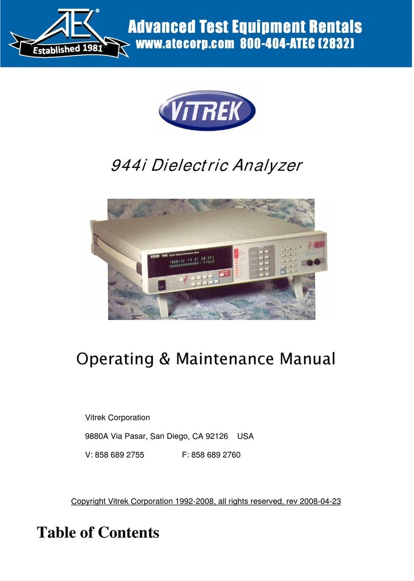
Vitrek
Vitrek 944i Installation and operation manual

Vitrek
Vitrek XiTRON XT560 User manual
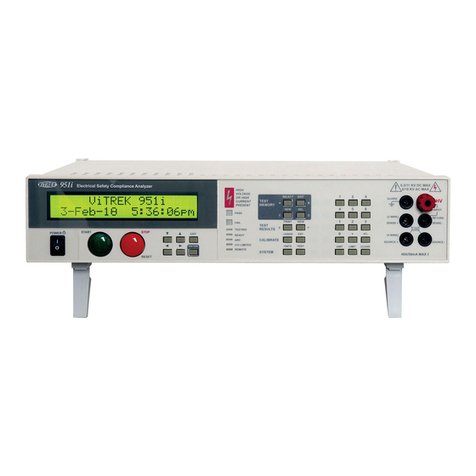
Vitrek
Vitrek 95 Series Installation and operation manual
Vitrek
Vitrek Xitron 2553 Installation instructions
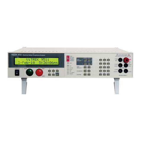
Vitrek
Vitrek 951i Installation and operation manual
Vitrek
Vitrek 4700 Operating instructions
Vitrek
Vitrek V4 User manual

Vitrek
Vitrek 930i Installation and operation manual

