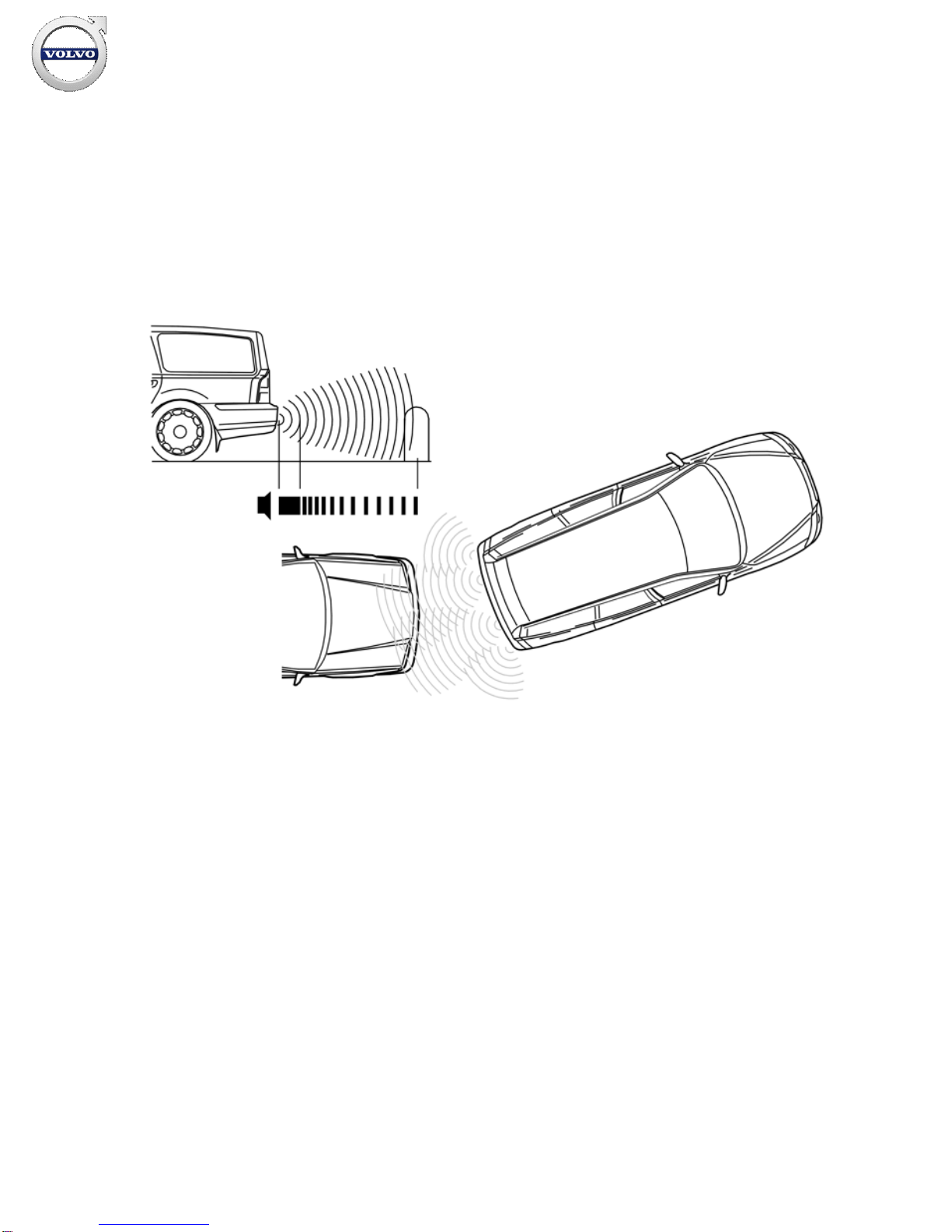
Installing the sensors
Applies to the V70
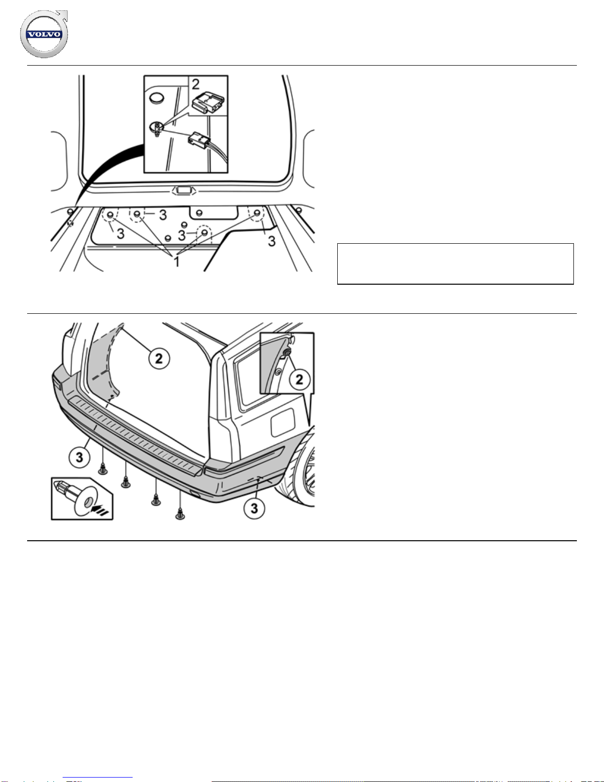
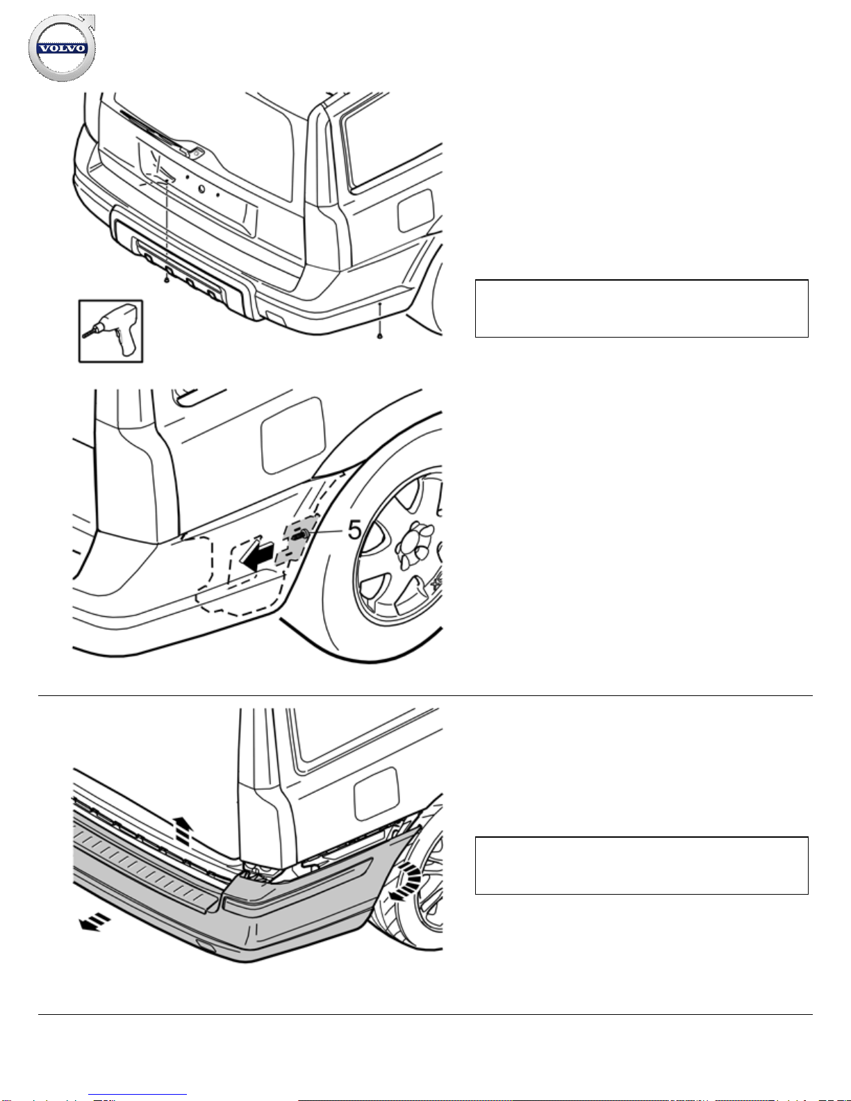
Pre
-drill the holes through the centre of the markings (1). Use a
Ø3 mm (1/8
”)
diameter drill bit. Drill from the inside of the bumper
cover.
Drill out the hole. Use a Ø8.5 mm (21/64
”)
diameter drill bit.
Applies to the XC70
Illustration A
Measure out for locating the outer sensors, from the existing
markings on the inside of the skid plate.
Measure 86 mm (3 3/8
”) from the underside of the plastic catch
(1) and straight down. Mark this point. Following which, draw a
straight line from the centre of the existing marking to the point
just marked.
Measure 478 mm (18 13/16
”) from the centre of the existing
marking along the line, and mark there for the sensor's position.
Carry this out on the right and left-hand sides of the bumper.
Pre
-drill the holes in the two points marked in the bumper cover,
and in the two existing markings in the skid plate, using a Ø3 mm
(1/8”)
diameter drill bit.
Drill out the four holes. Use a Ø8.5 mm (21/64
”)
diameter drill bit.
Illustration B
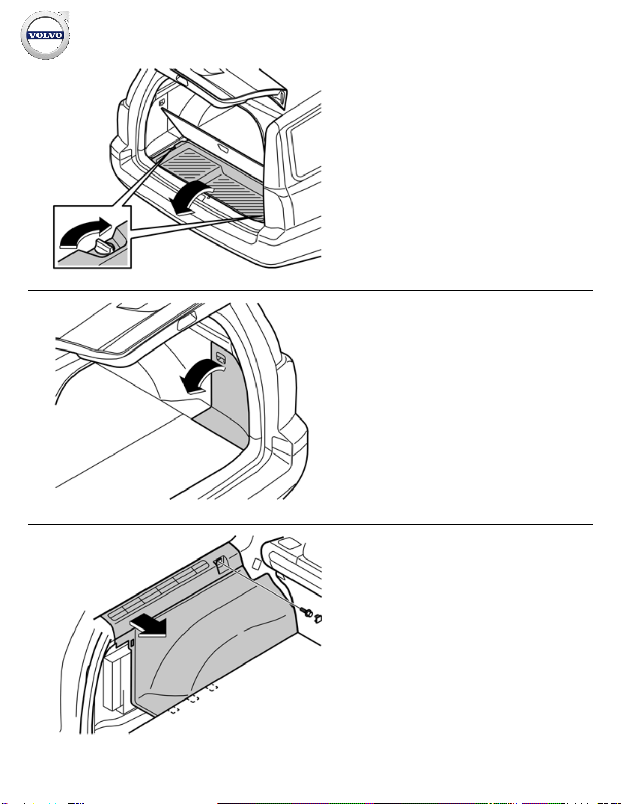
Removing the skid plate
Drill out the 4 x rivets
Remove the 10 x hooks (4)
Remove the splash guard.
Note!
When measuring, use a flexible measuring tool that follows the
form of the bumper cover.
Installation instructions, accessories
Volvo Car Corporation Gothenburg, Sweden