manuals.online logo
Brands
  1. Home
  2. •
  3. Brands
  4. •
  5. VOLYA
  6. •
  7. Greenhouse Kit
  8. •
  9. VOLYA FERMER-5.0 User manual

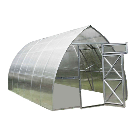
VOLYA FERMER-5.0 User manual

Технический паспорт
1
FERMER-5.0
Technical certificate
Assembling manual
p. 2-6
p. 7-26
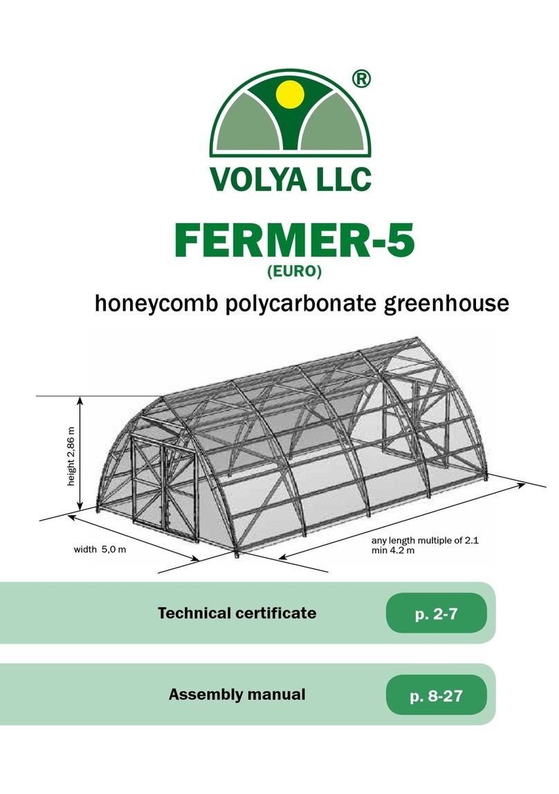
honeycomb polycarbonate greenhouse
design2011
any length multiple of 2.1.
min length 4.2 м
width 5.0 m
height 3.6 m
3
2
Technical certificateTechnical certificate
Perform assembling and operation of the greenhouse in strict accordance with
the manual and operating rules stated in the technical certificate. Please keep
this technical certificate for further reference.
The ”Fermer” greenhouse is designed and manufactured in accordance with SNiP
2.10.04-85 and generally intended for industrial cultivation of crops at farms and
peasant holdings.
Width of the greenhouse is 5 m. Area of covered ground depends on the length of the
greenhouse and for minimal length of 4.2 m is 21 m2. Height of the installed frame
is 3.6 m.
The frame of the greenhouse is made of galvanized iron 1 mm thick and is to be
assembled with screws, nuts and washers.
The greenhouse is fixed on the ground without foundation by digging special frame
endings or on a fundament using cleater angles. The type of fixing is determined by
a buyer.
The greenhouse may be completed with covering on buyer’s request.
Number of small windows is conformed to a buyer.
Description
ПАРАМЕТРЫ ПАКЕТОВ
COMPLETING WITH PACKAGES, PCS
L
length
of a
green-
house,
m
N – number of sections of a
greenhouse, excluding end sections.
FRAME (BASE LENGTH IS 4.2 M) INSERT (2.1 M FRAME
ELONGATION)
)
1 PACKAGE FERMER-5.0
2 PACKAGE FERMER-5.0
3 PACKAGE FERMER-5.0
4 PACKAGE FERMER-5.0
5 PACKAGE FERMER-5.0
6 PACKAGE FERMER-5.0
7 PACKAGE FERMER-5.0
8 PACKAGE FERMER-5.0
9 PACKAGE FERMER-5.0
1 PACKAGE INSERT
2 PACKAGE INSERT
3 PACKAGE INSERT
4 PACKAGE INSERT
5 PACKAGE INSERT
4,2 0
332222211
00000
6,3 1 1 1 1 1 1
8,5 2 2 2 2 2 2
10,6 3 3 3 3 3 3
12,7 4 4 4 4 4 4
14,9 5 5 5 5 5 5
17,0 6 6 6 6 6 6
19,1 7 7 7 7 7 7
21,2 8 8 8 8 8 8
23,4 9 9 9 9 9 9
2,1(N+2) N N N N N
Table 1
content dimensions, mm weight, no more
FRAME (BASE LENGTH 4.2 M)
1 PACKAGE
FERMER-5.0
(arc elements) 90х410х3000 11,6
2 PACKAGE
FERMER-5.0
(power arc straight elements) 90х75х2800 10,5
3 PACKAGE
FERMER-5.0
(end runners elements) 90х120х1990 32,36
4 PACKAGE
FERMER-5.0
(end side brace elements)
90х65х2360 11,12
5 PACKAGE
FERMER-5.0
(elements and strips for doors) 90х70х2720 17,10
6 PACKAGE
FERMER-5.0
(elements and strips for doors) 90х55х1145 2,62
7 PACKAGE
FERMER-5.0
(elements and strips for gates) 90х125х2620 36,4
8 PACKAGE
FERMER-5.0
(fixtures, component parts and sealing)
320х330х280 18,4
9 PACKAGE
FERMER-5.0
(outermost ridge)
2122х126х45 5,0
INSERT (2.1 M FRAME ELONGATION)
1 PACKAGE
INSERT
(arc elements) 90х410х3000 11,58
2 PACKAGE
INSERT
(power arc straight elements) 90х75х2800 15,7
3 PACKAGE INSERT (runners elements)
90х120х2080 35,2
4 PACKAGE
INSERT
(fixtures and component parts for insert) 60х130х130 1,58
5 PACKAGE INSERT (ridge)
2156х126х45 5,0
PACKAGE PARAMETERS
DETAILED PARTS LIST “FRAME” (4.2 M)
marking name quantity (pcs) length (m)
1 PACKAGE FERMER
4
Arc 2 3,08
20
Ridge arc 2 1,759
2 PACKAGE FERMER
5
Arc strainer 2 2,73
7м
Radial strainer 2 0,3
1
Foundation stay brace 2 0,84
11в
Girder 1 2,8
29
Top ridge girder 1 1,76
3
Support 2 0,30
3 PACKAGE FERMER
2к
End runner 10 2,0
2кн
Bottom end runner 4 2,0
4 PACKAGE FERMER
укос
Longitudinal stiffness side brace 4 2,36
5 PACKAGE FERMER
9
Stay brace 2 2,70
10ц
Central strainer 1 2,72
1
Foundation stay brace 2 0,84
3
Support 2 0,3
П-11
Strip of a top girder 1 2,67
П-9
Strip of a doorway stay brace 2 2,62
6 PACKAGE FERMER
26
Side brace 2 1,14
Table 3
Table 2
5
4
Technical certificateTechnical certificate
DETAILED PARTS LIST “FRAME” (4.2 M)
marking name quantity (pcs) length (m)
7 PACKAGE FERMER
13в
Cleat 4 1,28
13вн
Bottom cleat 2 1,28
12вп
Right stay brace 2 2,6
12вл
Left stay brace 2 2,6
16к
Guiding bracket 8 0,08
14в
Diagonal 4 1,727
П12вп
Strip of a right stay brace 2 2,6
П13вн
Strip of a bottom cleat 2 1,28
Hasp 4 0,91
8 PACKAGE FERMER
Bolt М6х10 DIN 965 344
Bolt М6х14 DIN 933 658
Bolt М6х20DIN 933 74
Nut М6 DIN 934 1076
Bracker 26х17х16 (angle) 200
Hanger 12
Hinge ПН 1-130 left 4
Hinge ПН 1-130 right 4
Straight lug 40х90 4
Pull РС-80-2 4
Washer 6 692
Washer 6,3 320
Self-driving screw М4,8х22 DIN 7981 200
Penofol 1 15,7
Door seal 1 26
Door seal 1 19
9 PACKAGE FERMER
Outermost ridge 2 2,1
Table 3 DETAILED PARTS LIST «INSERT»
marking name quantity (pcs) length (m)
1 PACKAGE INSERT
20
Ridge arc 2 1,76
4
Arc 2 3,1
2 PACKAGE INSERT
5
Arc strainer 2 2,73
7м
Radial strainer 2 0,3
1
Foundation stay brace 2 0,84
11в
Girder 1 2,8
29
Top ridge girder 1 1,76
3
Support 2 0,30
3 PACKAGE INSERT
2
Main runner 10 2,1
2н
Bottom main runner 4 2,1
4 PACKAGE INSERT
Bolt М6х14 DIN 933 86
Bolt М6х20DIN 933 44
Nut М6 DIN 934 130
Washer 6 122
Washer 6,3 30
5 PACKAGE INSERT
Ridge 1 2,2
Table 4
7
6
Manual
Technical certificate
1. The manufacturer bears responsibility for the greenhouse frame complete
setup.
2. The manufacturer bears responsibility for the greenhouse assemblability in
accordance with the manual.
3. The manufacturer bears responsibility for the greenhouse durability under
specified magnitude of atmospheric actions.
4. Claim presentation period is 12 months from the date of purchase.
OPERATION RULESWARRANTY LIABILITIES
The greenhouse should be serviced in the winter period. The greenhouse has
durability under the action of snow loads way more than is required for greenhouses,
but less for some snow areas in comparison with the general construction standards.
According to SNiP 2.10.04-85 «Greenhouses and seedbeds» «weight of snow blanket
on 1 m2 of horizontal surface of the ground in design of static greenhouses…» should
be taken from 10 to 40 kg/m2 depending on a snow region. This is much less than
the general construction standards for snow load, because it is assumed that on the
current greenhouses a snowcap is not preserved until the next snowfall. According
to the results of strength tests the limits of durability of the greenhouse frame are
revealed: destroying snow load is 240 kg/m2, permissible load (with safety coefficient
1.4) – 180 kg/m2. The permissible load approximately corresponds to the thickness
of fresh snow 0.9 m and settled snow 0.45 m. Thus, in operation it is necessary to
prevent accumulation of snowcaps above specified limits. If the greenhouse is not
heated in winter, or it is supposed to use the greenhouse as an unheated housing,
awning, warehouse, etc., it is necessary to control the snowcap (to shift the snow
down with a wooden or plastic scraper, installed on a pole). For these variants of
operation it is possible to supply reinforced frames with a reduced interval between
the power arcs under the snow load specified by the customer.
Do not allow damage to the frame, and if it happened, then hold timely repairs.
Warranty conditions
Warranty liabilities do not apply to cases of:
1. Greenhouse installation with violation of requirements of the manual.
2. Violation of the rules of operation.
3. Inappropriate use of the greenhouse.
4. Floods, hurricanes and other natural disasters.
Manufacturer: VOLYA LLC,
per. Severny, 8, Dubna, Moscow region, 141983, Russia.
The manufacturer bears responsibility for quality of products in accordance with RF CC. The
manufacturer reserves the right for greenhouse
engineering design changes.
Date of manufacture:
Cleaning and washing of polycarbonate sheets
1. Rinse sheet with warm water.
2. To remove dirt, wash it with mild soap solution or domestic detergent using a soft
cloth or sponge.
3. To remove water, rinse the sheet with cold water and wipe it with a soft cloth.
Never use abrasives or high-alkali detergents for cleaning
polycarbonate sheets. Dry wiping damages covering layer of
the covering and shortens its service life. Never rub surface of
polycarbonate sheets with a brush, metalized fabric or other abrasive
materials.
Do not use sulphur cartridges for disinfecting greenhouse against
fungal and bacterial agents in order to prevent corrosion (darkening)
of the frame.
It is not allowed to install the greenhouse without fastening on the ground because
of the large sail area of the greenhouse and the possibility of floating away the
unfastened greenhouse.
9
8
Manual
Manual
«FERMER» GREENHOUSE INSTALLATION MANUAL
The general view of the frame is presented in g. 1, with an anteroom - Fig. 1a
(the anteroom is purchased separately at the request of a buyer). The frame is
assembled from the shape numbered parts. Medium shape shelves are facing
the covering.
Indexes:
м - small;
б - big;
к – outermost (along the length of greenhouse);
н - bottom;
ц - central;
в – a gate;
п - right;
л - left;
П – a strip;
- -
the arrow indicates installation direction according to manuals’ schemes.
Terminology:
Left side is from the left when standing outside of the greenhouse in front
of the door.
Right side is from the right when standing outside of the greenhouse in
front the door.
Assembly units are lettered and shown in figures. The greenhouse is assembled
by means of bolts of M6, nuts, washers, screws, etc. Joints are accomplished by
overlapping of details and by fastening across the holes. Install bolts, nuts and
washers in all places indicated in the instruction.
The greenhouse assembly is presented in stages, at each stage the assembly
units «before» and «after» are shown. The figures of the units do not show the
nuts with washers that are installed from the inside of the sha
When assembling, be careful not to damage parts since they are not rigid
enough until they are fully assembled
Use additional tools to assemble:
-a wrench 10;
-a screwdriver
-a drill with a borer Ø 6.5;
-a stepladder 3m high;
-a fret saw;
-a knife.
1.
2.
3.
4.
5.
Introduction
Be careful while assembling! Parts have sharp angles. Avoid hand cuts! Work in
protective gloves.
Some parts have free holes
resulted from uniformity of
parts.
Do not break the instructions!
Do not install bolts with nuts
without washers, for this leads
to strength reduction of the
frame.
6.
INSTALLATION SEQUENCE
Stage Name page
1End wall assembly 12-14
2Installation of runners on the end wall 14
3Power arc assembly 15
4
End section assembly:
end section assembly;
Installation of longitudinal stiffness side braces on the
end section
16
5End section installation 17
6Extension of the frame length by the insert 18
7Second end section assembly 19
8Attaching the second end section to the frame 19
9 Doors and gate assembly 20-22
10 Installation of covering and seals 22-28
11
10
Manual Manual
GENERAL VIEW OF THE GREENHOUSE FRAME WITH
EXTENDING
INSERTS
Б
Г
К
И
Ж
В
Е
Fig. 1
General view of the greenhouse
with two inserts, total length is
8.4 m.
А
General view of the greenhouse
with an insert.
Fig. 1б
Д Е
Ж И К
GENERAL VIEW OF THE GREENHOUSE FRAME WITH EXTENDING
INSERTS
Г
ВА Б
20
20
20
2
2
5
1
1
1
5
5
5
4
3
9
10ц
4
4
4
2
2
2
2к
2кн
2к
26
26
11
укос
укос
укос
Д
ONE «INSERT» extends the
greenhouse by 2.13 m.
Number of the inserts for the
greenhouse is not limited.
Fig. 1а
13
12
Manual
Manual
Е
Ж
П9
1
3
9
10ц
26
INSTALLATION SEQUENCE
screw М6х14
washer 6
STAGE 1
Assembly of the end
wall.
Assembly is carried out according
to the figure 1.1.
INSTALLATION SEQUENCE
Б
А
В
Г
Д
Е
Ж
Fig. 1.1
General view of the end wall
А
Б
В
angle
П-11, П-10, П-9
sunken screw
М6х10
Determine the places of installation
of angles in accordance with fig.1.8.
and install the angles together with
the strip П-11, П-10, П-9.
Strips with the angles are installed
after assembling of the main shaped
parts.
11, 10, 9
20
29
20
4
11
П11
Д
26 4
1
4
20
Г
7м
5
4
15
14
Manual Manual
INSTALLATION SEQUENCE
-places of
installation of
angles for further
fastening of
covering to an end
Fig. 2
2кн
2к
2к
2кн
Fig. 1.8
General view of the end
wall and location of the
angles for fastening of
polycarbonate.
Assembly is carried out
according to the fig. 2.
Installation of runners
on the end wall.
STAGE 2
The assembled end wall is
installed in the horizontal
plane. To arcs 4 and 20
and girders of the end wall
are alternatively joined
end runners 2к и 2кн align
the side flanges of shapes.
Runners deviate from
the vertical under their
own weight and abut
against side walls of
shapes of arcs 4 (until the
next operation).
angle
INSTALLATION SEQUENCE
End section assembly.
Fig.4.2.
Installation of longitudinal
stiffness side braces.
STAGE 4
Fig.4.1.
2к
укос укос
STAGE 3
Assembly of the power
arc
Assembly of the power
arc is carried out in a
horizontal plane similar
to the assembly of the
end wall.
Assembly is carried out
according to the fig.4.1.
The assembled power arc
is brought to the end wall
with the installed runners,
is raised to the height
of the end runners and
joined with their upper
ends. It is recommended
to connect the outermost
and middle runners first.
For the initial fixation
of the power arc on the
runners, participation of
three people is required
for holding of the frame.
screw
17
16
Manual
Manual
STAGE 5
In the variant of
installation of the
greenhouse without a
foundation, marking
of axes is made on the
ground in accordance
with fig. 5.1 and holes
70 cm deep are dug for
foundation stay braces
with supports.
In the variant of
installation of the
greenhouse on
a foundation in
accordance with fig.
5.1, cleater angles
are mounted to the
foundation for the
subsequent fastening on
them bottom ends of arcs
in accordance with fig.
5.2 without foundation
stay braces.
The end section is lifted
and placed in a vertical
position on the prepared
place.
INSTALLATION SEQUENCE
End section installation
200*
20422132
L=4084+2132хN*
21322042
Fig. 5.1
Fig. 5.2
5000
200*
84
100
200*
200*
45
42
100
*N -number of sections of the greenhouse, excluding end sections, ref. p.2 table 1
2
STAGE 6
Extension of the frame
length.
Fig. 6
4
5
2
Assembled power arc (or
other end wall, depending
on the needed length
of the greenhouse) is
brought to the assembled
end section at the
distance of the main
runner and joined to
it with the use of main
runners 2 and 2н align
the side flanges of shapes
(fig. 6).
It is recommended to
connect the outermost
and middle runners first,
using a stepladder.
INSTALLATION SEQUENCE
Next power arc is joined
to the power arc that has
already been connected,
and so on all the arcs are
alternatively joined.
19
18
Manual Manual
Gate assembly.
GATE ASSEMBLY
А
В
Г
Ж
З
Б
Д
Е
13-в
14-в
13-в
14-в
12-в-л
13-вн
П-13-вн
12-в-п
П-12-в-п
Fig. 9
The gate is assembled in
the same way. Joints are
shown in the figures.
Strips and other surface
mounted components
are installed after the
main shape parts are
assembled.
STAGE 9
13-в
12-в-л
А
14-в 12-в-п
13-в
Б
screw
screw
В
12-в-л
GATE ASSEMBLY
13-в
12-в-п
Д
Е
П-12-в-п
12-в-п
screw
screw
14-в
14-в
13-в
Г
12-в-л
16-к
Ж
12-в-л
З
13-вн
П-13-вн
21
20
Manual
Manual
GATE ASSEMBLY
Fig. 9.1
Arrangement of
angles for fastening
of polycarbonate on
the gate.
Install honeycomb polycarbonate with a specified side facing outwards
(sunward); this side has a covering layer (make sure to clarify it on
buying or prior to installation). Covering layer is usually placed on the
side with notations on the shipping film. The film is transparent on the
opposite side of a sheet. After marking the sheet but prior to cutting
it, mark the side with the covering layer on each piece of the sheet:
when the shipping film is removed sheet sides look the same. Shipping
film shall be removed from the both sides immediately before fastening
covering on the frame.
Cut the sheets using a fret saw or a fine-pitch arm saw.
STAGE 10
Installation of covering
CUTTING LIST OF COVERING OF AN END
Fig. 10.3
Cutting list of covering
for an end of the
greenhouse 5.0 m wide.
CUT POLYCARBONATE SHEET IN STRICT ADHERENCE TO FIG. 10.3
Honeycomb polycarbonate sheet size 2100 х 12000 MM
2100
27002700
2610
6000
2610 27002700
12000
1170
1330
remainder
gate
140
140
2100
26102610
1330
remainder
gate
gate
gate
23
22
Manual
Manual
FASTENING OF COVERING
Fasten the pieces of
covering on the end to
the angles with the use of
washers and self-tapping
screws (fig.10.4).
Places of fastening of
pieces of covering to each
other with the use of a
permanent polycarbonate
connecting shape are
shown in fig. 10.5.
permanent
connecting shape
Fig. 10.5
Using a knife, adjust covering
pieces to arcs 4 and girder
20, and then install sealing
prole in accordance with
fig. 10.6
4
2к, 2кн
end
covering angle
washer 32х6,3
Fig.10.4
end
covering
end seal
4
Fig. 10.6
Fig. 10.7
FASTENING OF COVERING
- places of fastening
of door seals.
- places of fastening
of penofol.
Seals are installed in
accordance with
fig. 10.7, 10.8
door seal
hinge
gate
door seal
Fig. 10.8
penofol
penofol
gate
gate gate
gate
5мм
self-tapping screw
25
24
Manual
To cover the top of greenhouses 12000 x 21000 mm sheets are cut into pieces with
observance of right angle of the cut line to the side edge of the sheet, fig.10.10.
Reminders are used to cover the top of the end.
FASTENING OF COVERING
Fig. 10.10
Fig. 10.11
end seal
end covering
Outermost panel
4
5000 5000 2000
980
2100
12000
cut line
cut line
The outermost panels of covering are installed in
accordance with fig. 10.11.
Fasten the base of a dismountable connecting shape
with bolts M6 on arcs, using a drill with a borer Ø 6.5.
5000 5000 2000
2100
12000
cut line
cut line
1490
1490
980
Manual
Fig. 10.12
- places of fastening of washers
FASTENING OF COVERING
ridge shape
Fasten the panels with the washers in accordance with fig. 10.12,
installing the ridge shape on the upper joint of panels, fig. 10.13.
Fig. 10.13
covering covering
screw М6х20
26
Manual
Install lugs and handles on the door.
Fig. 10.14
covering
4
2
2
cover+base
covering
Connect the side joints of covering together with the
use of a dismountable connecting shape (cover +
base) 10.14. The base is fastened to the arc 4 and
girder 20 with bolts.
FASTENING OF COVERING
Технический паспорт
28
27102605 7301200240026055210 2710 9502500 12000
MANUFACTURER:
LLC «VOLYA», DUBNA, MOSCOW REGION.
phone/fax: (496) 217-17-17,
(495) 745-85-59
www.perchina.ru
e-mail: info@perchina.ru
EN
THIS MANUAL CANNOT BE REPRODUCED IN ANY FORM, IN WHOLE OR IN
PART, WIHOUT AN EXPRESS WRITTEN PERMISSION OF «VOLYA» COMPANY

Other VOLYA Greenhouse Kit manuals

VOLYA VENT User manual

VOLYA

VOLYA VENT User manual

VOLYA FERMER-4,2 User manual

VOLYA

VOLYA FERMER-4,2 User manual

VOLYA FERMER-5 User manual

VOLYA

VOLYA FERMER-5 User manual

VOLYA Sigma 2021 Euro Programming manual

VOLYA

VOLYA Sigma 2021 Euro Programming manual

VOLYA DACHNAYA STRELKA 2020 User manual

VOLYA

VOLYA DACHNAYA STRELKA 2020 User manual

VOLYA DACHNAYA STRELKA-3 Programming manual

VOLYA

VOLYA DACHNAYA STRELKA-3 Programming manual

VOLYA Dachnaya Tryoshka Programming manual

VOLYA

VOLYA Dachnaya Tryoshka Programming manual

VOLYA FERMER-3,5 User manual

VOLYA

VOLYA FERMER-3,5 User manual

VOLYA SIGMA 2021 User manual

VOLYA

VOLYA SIGMA 2021 User manual

VOLYA DACHNAYA DVUSHKA User manual

VOLYA

VOLYA DACHNAYA DVUSHKA User manual

VOLYA DACHNAYA-STRELKA 2011 User manual

VOLYA

VOLYA DACHNAYA-STRELKA 2011 User manual

VOLYA Alfa User manual

VOLYA

VOLYA Alfa User manual

VOLYA DACHNAYA DVUSHKA Programming manual

VOLYA

VOLYA DACHNAYA DVUSHKA Programming manual

VOLYA SIGMA EURO User manual

VOLYA

VOLYA SIGMA EURO User manual

VOLYA PRIMA 3 2022 User manual

VOLYA

VOLYA PRIMA 3 2022 User manual

VOLYA 2017 User manual

VOLYA

VOLYA 2017 User manual

VOLYA ORBITA Programming manual

VOLYA

VOLYA ORBITA Programming manual

VOLYA ORBITA Programming manual

VOLYA

VOLYA ORBITA Programming manual

VOLYA SIGMA 2020 User manual

VOLYA

VOLYA SIGMA 2020 User manual

VOLYA PRIMA 4 User manual

VOLYA

VOLYA PRIMA 4 User manual

Popular Greenhouse Kit manuals by other brands

ClearSpan R030A00007 manual

ClearSpan

ClearSpan R030A00007 manual

ClearSpan 30' Wide Pony Wall Building instruction manual

ClearSpan

ClearSpan 30' Wide Pony Wall Building instruction manual

Dancover HGSA1010 manual

Dancover

Dancover HGSA1010 manual

Outsunny 84H-080V00 manual

Outsunny

Outsunny 84H-080V00 manual

Robinsons Radley Series Assembly instructions

Robinsons

Robinsons Radley Series Assembly instructions

GrowSpan 113170 manual

GrowSpan

GrowSpan 113170 manual

FVG Romi Profiline 6.0 Instructions for use

FVG

FVG Romi Profiline 6.0 Instructions for use

OCTOPOT Hybrid Grow System manual

OCTOPOT

OCTOPOT Hybrid Grow System manual

Dancover GH152180 manual

Dancover

Dancover GH152180 manual

HI 62365 Directions for use and safety instructions

HI

HI 62365 Directions for use and safety instructions

Deuba 4250525324136 instructions

Deuba

Deuba 4250525324136 instructions

Palram Americana 12'x12' Hybrid Glazing Assembly instructions

Palram

Palram Americana 12'x12' Hybrid Glazing Assembly instructions

juwel BIO PROTECT 130/60 manual

juwel

juwel BIO PROTECT 130/60 manual

Growers SOLUTION DAKOTA Installation

Growers SOLUTION

Growers SOLUTION DAKOTA Installation

Vitavia Flora 1 Assembly instructions

Vitavia

Vitavia Flora 1 Assembly instructions

ACD PRESTIGE MR2 H manual

ACD PRESTIGE

ACD PRESTIGE MR2 H manual

Vitavia VA0002-DM Assembly instructions

Vitavia

Vitavia VA0002-DM Assembly instructions

Royal Well Sweet Tomato manual

Royal Well

Royal Well Sweet Tomato manual

manuals.online logo
manuals.online logoBrands
  • About & Mission
  • Contact us
  • Privacy Policy
  • Terms and Conditions

Copyright 2025 Manuals.Online. All Rights Reserved.