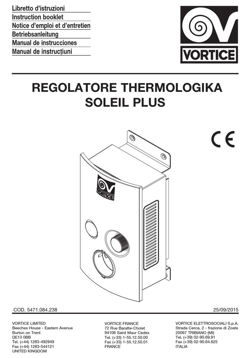
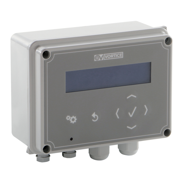
Vortice CHANGEOVER TF User manual

Libretto istruzioni
Instruction booklet
CONT OLLE
CHANGEOVE TF
VORTICE LIMITED
Beeches House - Eastern Avenue
Burton on Trent
DE13 0BB
Tel. (+44) 1283-492949
Fax (+44) 1283-544121
UNITED KINGDOM
VORTICE FRANCE
15/33 Rue Le Corbusier
Europarc
94046 CRETEIL Cedex
Tel. (+33) 1-55.12.50.00
Fax (+33) 1-55.12.50.01
FRANCE
VORTICE ELETTROSOCIALI S.p.A.
Strada Cerca, 2 - frazione di Zoate
20067 TRIBIANO (MI)
Tel. (+39) 02-90.69.91
Fax (+39) 02-90.64.625
ITALIA
COD. 5471.084.233 14/10/2015

2
Read the instructions contained in this booklet
carefully before using the appliance.
Vortice cannot assume any responsibility for
damage to property or personal injury resulting
from failure to abide by the instructions given in
this booklet.
Follo ing these instructions ill ensure a long
service life and overall electrical and mechanical
reliability.
Keep this instruction booklet in a safe place.
Prima di usare il prodotto leggere attentamente
le istruzioni contenute nel presente libretto.
Vortice non potrà essere ritenuta responsabile
per eventuali danni a persone o cose causati
dal mancato rispetto delle indicazioni di seguito
elencate, la cui osservanza assicurerà invece la
durata e l’affidabilità, elettrica e meccanica,
dell’apparecchio.
Conservare sempre questo libretto d’istruzioni.
Indice IT
Controller Autochangeover . . . . . . . . . . . 3
Collegamenti elettrici . . . . . . . . . . . . . . . . 3
Pressostato Differenziale . . . . . . . . . . . . . 5
Informazione importante per lo
smaltimento ambientalmente compatibile. . 6
Table of Contents EN
Autochangeover controller . . . . . . . . . . . 7
Wiring diagrams . . . . . . . . . . . . . . . . . . . . 7
Airflow pressure switch . . . . . . . . . . . . . . 9
Important information on
eco-compatible disposal. . . . . . . . . . . . . . . . 10

Controller Autochangeover
Questo controller è progettato :
-- per commutare il funzionamento dell’apparecchio a cui è collegato da un motore all’altro, in caso di guasto
al primo motore;
-- per garantire che il funzionamento dei motori, in modalità automatica, commuti dal motore 1 al motore 2
approssimativamente ogni 5 ore. In alternativa, uno dei due motori può essere selezionato e in caso di
blocco si arresterà. Un interruttore bipolare con spia è presente per portare in ON –OFF l’apparecchio, la spia
è accesa quando l’apparecchio è ON.
-- in una condizione di errore il controller commuterà automaticamente sul motore di standby. Il display sul
controller mostrerà quale motore è in funzionamento e quale è in errore. Oltre all’indicatore d’errore, un
contatto pulito a 230V 50Hz 5° si attiverà in caso di errore e rimarrà attivo finche non sarà eliminata la
condizione d’errore e il controller resetterà su OFF e nuovamente ON.
-- Così una condizione d’errore può essere monitorata da ogni dispositivo con un contatto pulito che si attiva
in caso di errore. Questo può essere un flussostato, un pressostato, un termostato, un umidostato, o
qualsiasi altro tipo di dispositivo
-- con un timer elettronico a bordo, per evitare che una condizione di errore venga mostrata all’accensione. Il
timer è impostato su circa 20 secondi ed eviterà false condizioni di errore all’avvio. Solo dopo che una
condizione d’errore sarà stata monitorata per almeno 20 secondi verrà attivato il motore di standby
-- per motori 230V 50Hz monofase con corrente massima a pieno carico di 6 AMPS ognuno. E’ presente un
fusibile per ogni motore, raggiungibile per la sostituzione sul lato frontale del controller
Collegamenti elettrici
3
ITALIANO
fault registered
Contacts make when
Volt Free Contacts
Or
switch contact made
Flap closed =
on each flap
airflow flaps whit swich
Twin fans whit non return
e.g. Airflow pressure swich
Fault swich
contact makes in fault
condition
{
CONNECTIONS
NO USER
NO USER
CONNECTIONS {
CONTROL
AUTO CHANGEOVER
S2
S1
Q2Q1M1
M2
N
NNE
E
EE
N
L
11
10
9
8
7
6
5
4
3
2
1
FAN 2
FAN 1
LNE
230V 50 Hz
6 amp. supply
Standard wiring diagram
for single phase motors
Schema di collegamento standard
per motori monofase

4
6 amp. supply
230V 50 Hz
E
NL
FAN 1
FAN 2
1
2
3
4
5
6
7
8
9
10
11
LNEEEE NNN
M2M1Q1Q2S1S2
AUTO CHANGEOVER
CONTROL
{
{
condition
contact makes in fault
Fault swich
e.g. Airflow pressure swich
Twin fans whit non return
airflow flaps whit swich
on each flap
Flap closed =
switch contact made
Or
Volt Free Contacts
Contacts make when
fault registered
NO USER
CONNECTIONS
CONNECTIONS
NO USER
OR
EXTERNAL
ELECTRONIC
SPEED
CONTROL
L=LIVE
N=NEUTRAL
VL=VARIABLE
LIVE
VL
N
L
TRANSFORMER
SPEED CONTROL TRICKLE/
BOOST
CONTACTS
MAKE FOR
BOOST
Standard wiring diagram
for single phase motors with speed control
6 amp. supply
230V 50 Hz
ENL
FAN 1
FAN 2
1
2
3
4
5
6
7
8
9
10
11
LNEEEE NNN
M2M1Q1Q2S1S2
AUTO CHANGEOVER
CONTROL
{
{
condition
contact makes in fault
Fault swich
e.g. Airflow pressure swich
Twin fans whit non return
airflow flaps whit swich
on each flap
Flap closed =
switch contact made
Or
Volt Free Contacts
Contacts make when
fault registered
NO USER
CONNECTIONS
CONNECTIONS
NO USER
OR
BMSON-OFF
ORREMOTE
SWITCH
EXTERNAL
P.I.R.
Standard wiring diagram
for single phase motors with P.I.R. or BMS
ITALIANO
Schema di collegamento standard
per motori monofase con controllo di elocità
Schema di collegamento standard
per motori monofase con P.I.R. o BMS

5
Pressostato differenziale
-- Installare il pressostato su una superficie liscia in un ambiente pulito e secco. Il
dispositivo deve essere posizionato su una superficie verticale, con gli ugelli
rivolti verso il basso. (fig.1)
-- Rimuovere il tappo di plastica dell’ugello P2. A questo punto entrambi gli ugelli
P1 e P2 sono a contatto con l’aria.
-- Installare l’ugello
nella parte di
condotto in
pressione, e lontano
dal ventilatore
abbastanza da
evitare turbolenze.
(fig.2).
-- Connettere un tubo
di plastica tra l’ugello
e l’ugello P2 del
pressostato.
-- Utilizzando un tester verificare la continuità elettrica tra i
terminali 1 e 3 del pressostato a ventilatori spenti, quindi
in assenza di flusso nel condotto (fig.3).
-- Accendere un ventilatore e tarare la sensibilità del
pressostato in modo tale da interrompere il contatto
elettrico. Se non si è ottenuta l’azione di switch, provare a
riposizionare l’ugello in una posizione nel condotto in cui
la pressione sia superiore, o controllare che il tubo non sia
piegato o schiacciato. Evitare aree in cui possono
verificarsi turbolenze, assicurarsi che l’ugello sia orientato
con la giusta angolazione rispetto al flusso.
-- Con il ventilatore acceso verificare la continuità elettrica tra i terminali 2 e 3 del pressostato.
-- Spegnere il ventilatore e verificare che tra i terminali 2 e 3 non ci sia continuità
-- Se non è possibile
ottenere un
appropriato switch
può essere
necessario inserire
un ugello nel lato di
condotto in
depressione (fig.4):
in questo caso P1 è
connesso in
corrispondenza
dell’uscita del
ventilatore, P2 in
corrispondenza dell’entrata
-- Per cablare l’interruttore per la continuità in presenza di flusso d’aria,usare i terminali 2 e 3.
-- Rimontare il coperchio sul pressostato apponendo esternamente, in modo che siano visibili dall'utente,
appropriata/e etichetta/e di sicurezza per avvisare sulla presenza di corrente elettrica quando collegato alla
tensione di rete.
ITALIANO
Attenzione:
togliere l’alimentazione prima di aprire!
!
11
22
FAN
AIRFLOW
DUCT
AIRFL . SWITCH
HOSE
NOZZLE
OPEN TO ATHMOSPHERE
P1 +
P2
-
33
COMMON
SWITCH
NO AIRFLOW
POSITIVE AIRFLOW
1
2
3
44
AIRFLOW
DUCT
NOZZLE
HOSE P1
+
P2
-
FAN
AIRFL.SWITCH
HOSE
NOZZLE
AIRFLOW
Voltaggio massimo 250 VAC
Corrente massima 1,5 A resistivi
N.B.
6
AVVE TENZA
Vortice suggerisce di utilizzare sempre in abbinamento il changeover e il pressostato. Tuttavia è possibile
utilizzare il changeover senza pressostato, per il controllo manuale e/o automatico dei motoventilatori, ma in
questo caso per particolari condizioni di guasto potrebbe non essere garantito il passaggio dell’aria nei
condotti dell’impianto.
Informazione importante per lo smaltimento ambientalmente
compatibile
IN ALCUNI PAESI DELL'UNIONE EU OPEA QUESTO P ODOTTO NON ICADE NEL CAMPO DI
APPLICAZIONE DELLA LEGGE NAZIONALE DI ECEPIMENTO DELLA DI ETTIVA AEE E QUINDI NON
È IN ESSI VIGENTE ALCUN OBBLIGO DI ACCOLTA DIFFE ENZIATA A FINE VITA.
Questo prodotto è conforme alla Direttiva EU2002/96/EC.
Il simbolo del bidone barrato riportato sull’apparecchio indica che il prodotto, alla fine della
propria vita utile, dovendo essere trattato separatamente dai rifiuti domestici, deve essere
conferito in un centro di raccolta differenziata per apparecchiature elettriche ed elettroniche
oppure riconsegnato al rivenditore al momento dell’acquisto di una nuova apparecchiatura
equivalente.
L’utente è responsabile del conferimento dell’apparecchio a fine vita alle appropriate strutture
di raccolta, pena le sanzioni previste dalla vigente legislazione sui rifiuti.
L’adeguata raccolta differenziata per l’avvio successivo dell’apparecchio dismesso al
riciclaggio, al trattamento e allo smaltimento ambientalmente compatibile contribuisce ad
evitare possibili effetti negativi sull’ambiente e sulla salute e favorisce il riciclo dei materiali di cui è composto il
prodotto.
Per informazioni più dettagliate inerenti i sistemi di raccolta disponibili, rivolgersi al servizio locale di smaltimento
rifiuti o al negozio in cui è stato effettuato l’acquisto.
I produttori e gli importatori ottemperano alla loro responsabilità per il riciclaggio, il trattamento e lo smaltimento
ambientalmente compatibile sia direttamente sia partecipando ad un sistema collettivo.
ITALIANO

Autochangeover controller
This controller is designed::
-- to automatically change from one motor to another in the event of a fault condition;
-- to ensure even duty of the motors, in its “Auto” mode, switch between motor 1 and motor 2 approximately
every 5 hours. Alternatively, either motor can be selected and will only switch to standby in a fault condition.
A double pole switch with neon is provided to switch the unit ON-OFF, the neon in the switch is illuminated
in the ON position;
-- so that in the event of a fault condition, the controller will automatically switch to standby motor. The display
on the front of the control will show which motor is running and which has a fault. In addition to the fault
indicator, a volt free contact rated at 230V 50Hz 5A will make under fault condition and stay made until the
fault is removed and the control reset by switching OFF and back ON;
-- so a fault condition can be monitored by any device or devices with a volt free contact which makes in a fault
situation. This can be an airflow switch, flow switch, pressure switch, thermostat, humidity switch or any other
suitable device;
-- with a built-in electronic timer to prevent a fault condition being shown at turn on. This timer is set for
approximately 20 seconds and will prevent spurious fault switching. Only after a fault condition has been
monitored for 20 seconds will the standby motor be switched on;
-- for 230V 50Hz SINGLE PHASE motors with a maximum full load current of 6 AMPS each. A fuse is provided
for each motor and is replaceable from the front of the controller.
Wiring diagrams
7
ENGLISH
fault registered
Contacts make when
Volt Free Contacts
Or
switch contact made
Flap closed =
on each flap
airflow flaps whit swich
Twin fans whit non return
e.g. Airflow pressure swich
Fault swich
contact makes in fault
condition
{
CONNECTIONS
NO USER
NO USER
CONNECTIONS {
CONTROL
AUTO CHANGEOVER
S2
S1
Q2Q1M1
M2
N
NNE
E
EE
N
L
11
10
9
8
7
6
5
4
3
2
1
FAN 2
FAN 1
LNE
230V 50 Hz
6 amp. supply
Standard wiring diagram
for single phase motors

8
ENGLISH
6 amp. supply
230V 50 Hz
E
NL
FAN 1
FAN 2
1
2
3
4
5
6
7
8
9
10
11
LNEEEE NNN
M2M1Q1Q2S1S2
AUTO CHANGEOVER
CONTROL
{
{
condition
contact makes in fault
Fault swich
e.g. Airflow pressure swich
Twin fans whit non return
airflow flaps whit swich
on each flap
Flap closed =
switch contact made
Or
Volt Free Contacts
Contacts make when
fault registered
NO USER
CONNECTIONS
CONNECTIONS
NO USER
OR
EXTERNAL
ELECTRONIC
SPEED
CONTROL
L=LIVE
N=NEUTRAL
VL=VARIABLE
LIVE
VL
N
L
TRANSFORMER
SPEED CONTROL TRICKLE/
BOOST
CONTACTS
MAKE FOR
BOOST
Standard wiring diagram
for single phase motors with speed control
6 amp. supply
230V 50 Hz
ENL
FAN 1
FAN 2
1
2
3
4
5
6
7
8
9
10
11
LNEEEE NNN
M2M1Q1Q2S1S2
AUTO CHANGEOVER
CONTROL
{
{
condition
contact makes in fault
Fault swich
e.g. Airflow pressure swich
Twin fans whit non return
airflow flaps whit swich
on each flap
Flap closed =
switch contact made
Or
Volt Free Contacts
Contacts make when
fault registered
NO USER
CONNECTIONS
CONNECTIONS
NO USER
OR
BMSON-OFF
ORREMOTE
SWITCH
EXTERNAL
P.I.R.
Standard wiring diagram
for single phase motors with P.I.R. or BMS

Airflow pressure switch
-- Mount airflow switch on a flat surface in a clean dry environment. Mount the
switch in vertical plane so that the nozzles are pointing down. (fig.1)
-- Remove plastic cover from P2 nozzle of airflow switch. Both P1 and P2 are now
open to athmosphere.
-- Mount nozzle in duct
where positive air
pressure is to be
monitored, and well
away from fan to
prevent turbulence
(fig.2)
-- Connect plastic tube
between nozzle and
P2 nozzle of airflow
switch. Please note
this is because air
flowing across the
nozzle will cuck air
from the nozzle as in a pilot tube.
-- Using a meter check the continuity between terminals 1
and 3 of the airflow switch with no airflow in the duct.
(fig.3).
-- Turn the fan on and measure between terminals 1 and 3
of the airflow switch, adjust switch until continuity is
broken. If no switching action is obtained, try repositioning
the nozzle to a position wher a higher pressure is in the
duct, and check the tube is not kinked. Avoid areas where
turbulence may occur, ensure nozzle is at a right angle to
the airflow.
-- With the fan still on check continuilly between terminals 2 and 3 of airflow switch.
-- Turn off the fan and measure between terminals 2 and 3 there should be no continuity.
-- If unable to ontain
proper switch
operation it may be
necessary to fit a
nozzle to the
negative side of the
duct as well, in wich
case P1 connects
to the fan outlet and
P2 to fan inlet (fig.4)
-- To wire up switch
for continuity when
airflow proven, use
terminals 2 and 3.
-- Replace cover on airflow switch and use appropriate safety labels if mains voltage is switched.
9
ENGLISH
Warning:
switch off power before opening! Maximum voltage 250 VAC
Maximum current 1,5 A resistive
NOTE
11
22
FAN
AIRFLOW
DUCT
AIRFL . SWITCH
HOSE
NOZZLE
OPEN TO ATHMOSPHERE
P1 +
P2
-
33
COMMON
SWITCH
NO AIRFLOW
POSITIVE AIRFLOW
1
2
3
44
AIRFLOW
DUCT
NOZZLE
HOSE P1
+
P2
-
FAN
AIRFL.SWITCH
HOSE
NOZZLE
AIRFLOW
!

WA NING
Vortice suggests using always combined the changeover and the pressure switch. However, it is allowed to
use the changeover without the pressure switch, to make automatic/manual control of fan motors, but in this
case for particular fault conditions the passage of air in the ducts may not be guaranteed.
Important information on environmentally compatible disposal
IN CERTAIN EUROPEAN UNION COUNTRIES THIS APPLIANCE IS NOT SUB ECT TO THE REQUIREMENTS
OF NATIONAL LAWS IMPLEMENTING THE WEEE DIRECTIVE; CONSEQUENTLY, THERE IS NO OBLIGATION
TO OBSERVE SORTED COLLECTION PROCEDURES WHEN DISPOSING OF THE APPLIANCE IN THESE
COUNTRIES.
This appliance complies with european directive 2002/96/ec.
Where an appliance is marked with the crossed-out wheelie bin symbol, this means that, at
the end of its useful life, the product has to be disposed of separately from household waste:
it must be taken to a sorted collection centre for electrical and electronic appliances or
returned to the retailer when a new equivalent appliance is purchased.
The user is responsible for taking the appliance to a designated collection centre at the end
of its useful life, and liable to penalties applicable under current statutory regulations on
waste disposal.
Appropriate sorted waste collection for subsequent recycling, treatment and eco-compatible
disposal of decommissioned appliances helps to prevent any possible negative impact on the environment and
on health, and favours recycling of the
materials used in the manufacture of the product.
For more detailed information on available waste collection systems, contact the local waste disposal service or
the shop where the product was purchased.
Manufacturers and importers fulfill their responsibility for recycling, treatment and eco-compatible disposal of
appliances both directly and by supporting joint initiatives.
10
ENGLISH

11

12

13
La Vortice S.p.A. si riserva di apportare tutte le varianti migliorative ai prodotti in corso di vendita.
Vortice S.p.A. reserves the right to make improvements to products at any time and without prior notice.

ATAGLIANDO INTE VENTO IN GA ANZIA
CE TIFICATE OF WO K PE FO MED UNDE GUA ANTEE
COUPON INTE VENTION SOUS GA ANTIE
DATA INTE VENTO
DATE OF WORK - DATE INTERVENTION
TIMB O CENT O ASSISTENZA
STAMP OF TECHNICAL ASSISTANCE CENTRE - CACHET SERVICE APRES-VENTE
TAGLIANDO INTE VENTO IN GA ANZIA
CE TIFICATE OF WO K PE FO MED UNDE GUA ANTEE
COUPON INTE VENTION SOUS GA ANTIE
DATA INTE VENTO
DATE OF WORK - DATE INTERVENTION
TIMB O CENT O ASSISTENZA
STAMP OF TECHNICAL ASSISTANCE CENTRE - CACHET SERVICE APRES-VENTE
TAGLIANDO INTE VENTO IN GA ANZIA
CE TIFICATE OF WO K PE FO MED UNDE GUA ANTEE
COUPON INTE VENTION SOUS GA ANTIE
DATA INTE VENTO
DATE OF WORK - DATE INTERVENTION
TIMB O CENT O ASSISTENZA
STAMP OF TECHNICAL ASSISTANCE CENTRE - CACHET SERVICE APRES-VENTE
TAGLIANDO INTE VENTO IN GA ANZIA
CE TIFICATE OF WO K PE FO MED UNDE GUA ANTEE
COUPON INTE VENTION SOUS GA ANTIE
DATA INTE VENTO
DATE OF WORK - DATE INTERVENTION
TIMB O CENT O ASSISTENZA
STAMP OF TECHNICAL ASSISTANCE CENTRE - CACHET SERVICE APRES-VENTE
B
C
D

ITALIA
Spedire la garanzia in busta
chiusa a:
Vortice Elettrosociali S.p.A.
Strada Cerca 2
Frazione di Zoate
20067 Tribiano Milano
OTHE COUNT IES
Please send the guarantee to
the retailer’s address in the
country where the appliance
has been purchased.
Autorizzo la Vortice
Elettrosociali S.p.A.
adinserire i miei dati
nelle sue liste e a
comunicarli a terzi
per l’invio di materiale
pubblicitario ed
informativo. In ogni
momento, a norma
dell’art. 13 legge
675/96, potrò avere
accesso ai miei dati,
chiederne la modica
o la cancellazione
oppure oppormi al
loro utilizzo scrivendo
a Vortice
Elettrosociali S.p.A.
Responsabile
trattamento dati -
Strada Cerca, 2 -
Frazione di Zoate -
20067 Tribiano (MI).
Non autorizzo
(barrare se interessa).
I do not authorize
(please tick if
required).
I authorize Vortice
Elettrosociali S.p.A.
and its local
distributors to include
my personal details
within their database
and they can use it
through a third party
for the despatch of
advertising material.
At any time, in
accordance with the
regulations in force
within my country. I
can have access to
details and can ask to
make changes, or
prohibit the usage of
my details.This will be
done by addressing
my request directly to
the headquarters of
the local distributor
where the appliance
has been bought.
UK-I ELAND
Send the guarantee
in sealed envelope to:
Vortice Limited
Beeches House
Eastern Avenue
Burton on Trent
DE13 0BB United Kingdom
I authorize Vortice
Ltd. to include my
personal details
within their database,
which they use, via a
third party for the
despatch of
advertising material,
at any time, in
accordance
with the regulations in
force within my
country.
I can have access
to my details and can
request changes, or
prohibit the usage of
my details.This will be
done by addressing
my request directly to
Vortice Limited
Beeches House
Eastern Avenue
Burton on Trent
DE13 0BB United
Kingdom.
I do not authorize
(please tick if
required).
F ANCE
Expédier la garantie sous
enveloppe cachetée a:
Vortice France
15-33, Rue Le Corbusier
Europarc - CS 30007
90046 CRETEIL CEDEX
Conformément à la
loi informatique et
liberté art. 27 du
27/01/78, vous
disposez d’un droit
d’accés et de
rectication des
donné es vous
concernant auprès de
Vortice France - 72,
Rue Baratte - Cholet-
94106 Saint Maur
Cedex.
Par notre
intermédiaire,
votre adresse pourra
être transmise à
des tiers.
Sauf opposition de
votre part (auquel cas
cochez la case ci
dessus).
ITALIA
CONDIZIONI DI GA ANZIA
VORTICE SPA garantisce i suoi prodotti per
24 mesi dalla data dell’acquisto che deve
essere comprovata da idoneo documento
scale (scontrino o fattura) rilasciato dal
venditore. Nel suddetto periodo di garanzia
VORTICE SPA si
impegna, dopo aver effettuato le opportune
valutazioni tecniche, a riparare o a
sostituire, gratuitamente, le parti
dell’apparecchio che risultassero affette da
difetti di fabbricazione. La presente
garanzia, da attivare nei modi e nei termini
di seguito indicati, lascia impregiudicati i
diritti derivanti al consumatore dalla
applicazione del D. lgs. 24/2002.Tali diritti,
conformemente alla legge, potranno essere
fatti valere esclusivamente nei confronti del
proprio venditore. La presente garanzia è
valida su tutto il territorio italiano.
Modalità e condizioni di attivazione della
garanzia
Gli interventi in garanzia (riparazioni o
sostituzioni del prodotto ovvero delle parti
difettose) saranno eseguiti presso uno dei
Centri di Assistenza Tecnica autorizzati da
VORTICE il cui indirizzo è disponibile
sull’elenco telefonico alfabetico o
contattando il numero verde 800.555.777.
La prestazione eseguita in garanzia non
prolunga il periodo della garanzia. Pertanto,
incaso di sostituzione del prodotto o di un
suo componente, sul bene o sul singolo
componente fornito in sostituzione non
decorre un nuovo periodo di garanzia ma si
deve tener conto della data di acquisto del
prodotto originario.
UK AND I ELAND
CONDITIONS OF WA -
ANTY
This guarantee is offered as an extra
benet and does not affect your legal
rights. All electrical appliances produced
by Vortice are guaranteed by the
Company for two years against faulty
material or workmanship.
If any part is found to be defective in this
way within the rst twenty months four
from the date of purchase or hire
purchase agreement, we or our
authorised service agents, will replace or
at our option repair that part without any
charge for materials or labour or
transportation, provided that the
appliance has been used only in
accordance with the instructions
provided with each appliance and has
been not connected to an unsuitable
electricity supply, or subjected to misuse,
neglect or damage or modied or
repaired by any person not authorised by
us.The correct electricity supply voltage
is shown on the rating plate attached to
the appliance.
This guarantee is normally available only
to the original purchaser of the appliance,
but the Company will consider written
applications for transfer.
Should any defect arise in any Vortice
product anda claim under guarantee
become necessary, the appliance should
be carefully packed and returned to your
approved Vortice stockist.This portion of
the guarantee should be attached to the
appliance.
F ANCE
CONDITIONS DE GA ANTIE
Votre appareil est couvert par notre garantie à
condition qu’il ne soit pas utilisé à des ns autres
que celles dénies dans nos ches techniques.
Il est garanti pendant deux ans pour l’ensemble
des pièces qui le compose, contre tout vice de
fabrication ou défaut de matiére,
et ce, dès la date de la première mise en service
Cette garantie s’applique au remplacement gratuit
ou à la réparation sans frais des pièces reconnues
défectueuses par nos services; elle ne peut, en
aucun cas, donner lieu à des dommages et
intèréts.
Les frais de transport restant à la charge de
l’utilisateur, et le material voyage à ses risques et
perils.
La garantie sera sans effet si:
• L’appareil a subi un démontage, un
remplacement, de piéce ou une réparation hors
de nos ateliers.
• S’il a été survolté.
• S’il a été utilisé dans une atmosphére
corrosive.
• S’il a été deterioré ou brisé par accident (choc
ou chute....) ou même pendant le transport (le
transporteur est seul responsable).
• La garantie ne s’applique pas sur les pieces à
durée de vie limitée, (ltre charbon, charbon
pour collecteur etc....)
En cas de panne. N’écrivez pas, mais retournez
directement l’appareil soigneusement emballé à
notre service après vente voir coordonnées sur
www.vortice-france.com ou au 01.55.1250.00.
oindre à l’envoi: le présent certicat de garantie
validé par le vendeur, accompagné d’une note
explicative succinte.

DATI UTENTE / CUSTOME DATA / COO DONNÉES DE L’UTILISATEU
nome / name / nom ______________________________________________
cognome / surname / prenom _________________________________
via / street / rue __________________________________________________
cap / post code / code postal _____________________________________
città / town ______________________________________________________
TIMB O IVENDITO E
stamp of supplier
cacher du vendeur
2GA ANZIA - GUA ANTEE - GA ANTIE
DA SPEDI E (entro 8 giorni dall’acquisto)
TO SEND (within 8 days from date of purchase)
A ETOU NE (dans les 8 jours après l’achat)
Per poter usufruire della garanzia il cliente deve compilare e rispedire alla VORTICE
SPA, entro 8 giorni dall’acquisto, la “Parte 2” del tagliando di garanzia, all’indirizzo
e con le modalità in tale parte riportate.
La “Parte 1” del tagliando di garanzia deve essere conservata e presentata,
unitamente al documento scale (scontrino o fattura) rilasciato dal venditore al
momento dell’acquisto, al Centro di Assistenza autorizzato VORTICE che dovrà
eseguire l’intervento in garanzia.
This warranty must be attached to the appliance should it need to be returned for
servicing.
N.B. Guarantee is only valid if all details are completed correctly.
ATTENTION: pour bénécier de la garantie, le présent certicat doit
obligatoirement
accompagner l’appareil présumé défectueux. Le certicat doit porter le cachet du
revendeur et la date d’achat.
A defaut, la garantie sera comptée à partir de la date de sortie d’usine.
GA ANZIA - GUA ANTEE - GA ANTIE
DA CONSE VA E
TO BE ETAINED
A CONSE VE
Esclusioni
La presente garanzia non copre:
• Le rotture provocate dal trasporto.
• I difetti o guasti derivanti da uso non corretto o improprio da parte del cliente.
• I difetti derivanti dal mancato rispetto delle avvertenze e condizioni d’uso
indicate nel libretto di istruzioni ed uso allegato al prodotto.
• I difetti derivanti da non corretta installazione ovvero da una installazione
effettuata senza rispettare quanto previsto nel relativo capitolo del libretto di
istruzioni ed uso.
• I guasti derivanti da un errato allacciamento alla rete di alimentazione elettrica o per tensione di alimentazione diversa da quella prevista per
l’apparecchio, ovvero diversa dal limite stabilito dalle norme CEI (+/- 10% del valore nominale).
La presente garanzia non copre, inoltre, gli eventuali difetti derivanti da una cattiva manutenzione ovvero da interventi effettuati da personale non
qualicato o da terzi non autorizzati.
1
Dichiaro di aver preso atto delle condizioni di garanzia specicate sul certicato in mio possesso e autorizzo la gestione dei miei dati personali (v.
retro).
I have read and understood the terms and conditions of this guarantee and I authorise the processing of my personal details (see overleaf).
Suivant les conditions de garantie dénies par le certicat en ma possession j’autorise l’utilisation de mes coordonnées (voir au verso).
rma / signature / signature _________________________________
DATA
DATA - DATE
ANNI
YEARS
2
ANNI
YEARS
2
SPEDITO IL
MAILING DATE - ENVOYÉ PAR LA POSTE LE
CONF.
-----------------
COLL.
TIMB O IVENDITO E
stamp of supplier
cacher du vendeur
SPEDITO IL
MAILING DATE - ENVOYÉ PAR LA POSTE LE
ACQUISTATO IL
DATE OF PURCHESE - DATE DE L’ACHAT
DATA
DATA - DATE
This manual suits for next models
1
Table of contents
Languages:
Other Vortice Controllers manuals

Vortice
Vortice SCRR/M User manual

Vortice
Vortice VORT DELTA T User manual

Vortice
Vortice IRET 6 User manual

Vortice
Vortice CNU User manual

Vortice
Vortice SCRR5 User manual

Vortice
Vortice IRM5 Series User manual

Vortice
Vortice Vort Delta T WIFI User manual

Vortice
Vortice C 1.5 User manual

Vortice
Vortice SCB5 User manual

Vortice
Vortice C 2.5 User manual