Würth MIG 180-5 User manual

3
MIG 180-5
MIG/MMA WELDER
Description
The MIG 180-5 is a DC inverter MIG welder. It uses 1
~Phase
220/230V, 50/60 Hz AC power. A 20 amp time delay fuse or
circuit breaker is recommended. The MIG 180-5 (MIG/MMA
Welder) is ideal for Do-It-Yourself projects or for any kind of light
maintenance. Your purchased MIG welder can weld carbon steel
and stainless steel.
Unpacking
1.1 Open cardboard box, bags or styrofoam
packaging containing the welder and accessories.
1.2 Check that contents is as in the list below.
Item Qty.
MIG DC Inverter Welder 1 unit
MIG gun 1 pc.
Grounding cable with earth clamp 1 pc.
ф8 Gas hose 4 m
User manual 1 set
1.3 After unit unpacking, inspect carefully for any damage that may have occurred
during transit. Check for loose, missing, or damaged parts. In case of shipping damage contact
carrier
immediately.
GB
WARNING
Please read and save these instructions. Read through this owners manual carefully before using
product. Protect yourself and others by observing all safety information, warnings, and cautions.
Failure to comply with instructions could result in personal injury and/or damage to product or
property. Please retain instructions for future reference.

4
Specifications and dimensions
Description Specification
Model MIG 180-5
Input power V 220 230
Frequency Hz 50/60
Rated input current A 32
Rated input capacity KVA 7.4
No-load voltage V 65 69
Rated working voltage V 23
MIG welding current A 30~180
Rated duty cycle % 25
Welding current(10min)
A
25%@180
10min/100% A 90
Efficiency η 85%
Power factor Cosφ 0.75
Insulation class H
Enclosure protection IP 21S
Cooling method Fan cooled
Dimension L×W×H cm 50×22×38
Weight kg 14

5
Getting to know your welder
POWER INDICATOR
When the machine is turned on, the power indicator is lit.
ALARM INDICATOR
When the thermal indictor is lit, it shows that the machine is overloaded and the internal temperature is
too high. Welding output will turn off automatically but the fan will still be working. When the internal
temperature is decreased, the overload light will turn off and the machine will be ready to weld again.
WORKING INDICATOR
Lights up when the unit is the welding mode.
WELDING VOLTAGE ADJUSTMENT KNOB
Sets output voltage. Refer to the “SET UP” chart inside the wire feed compartment.
WIRE SPEED ADJUSTMENT KNOB
Adjusts the wire feeding/amperage speed. Controls the speed that the welding wire feeds out of the
welding Torch and adapts output amperage somewhat.
MIG/Stick/TIG SELECTOR
When MIG welding, this switch should be turned in “MIG” position, when stick welding the switch
should be in the “stick” position.
2T/4T SELECTOR
Power Cord
Power Switch
MIG Torch
Power
Indikator
Alarm
Indicator
Wire Speed
Adj. Knob
Welding
Voltage Adj.
Knob
W
elding
Indicator
2
T
/4
T
Selector
Grounding
Cable with
Clamp
Gas Hose
MIG/Stick/
T
IG
Selector

6
Two touch/Four touch operation mode switch.
MIG GUN
The welding wire is driven through the welding cable and trough the MIG Torch onto the workpiece.
It is attached to the drive system.
POWER SWITCH
In the “OFF” position no mains power is being supplied.
In the “ON” position power is supplied to the mains transformer and the control circuit.
POWER CORD
The power cord connects the welder to the 220/230 volt power supply, 20 amp power supply mains
socket to supply power to the welder.
EARTH GROUNDING CABLE with EARTH CLAMP
Use earth clamp to connect earth cable with work piece.
WELDING CABLE with ELECTRODE HOLDER
Used for stick welding.
GAS HOSE
Used to connect the machine to the regulator.
SHIELDING GAS PRESSURE REGULATOR
Installs on the shielding gas cylinder for MIG welding with solid wires.

7
Installation
1. Power requirement
AC single phase 220V/230V, 50/60 Hz mains supply fused with a 20 amp time delayed fuse or
circuit breaker is required.
WARNING
• High voltage danger from power source! Consult a qualified electrician for proper
installation of needed socket. This welder must be grounded while in use to protect the operator from
electric shock.
• Do not remove grounding prong or alter the plug in any way. Do not use any adapters between the
welder’s power cord and the power source socket. Make sure the POWER switch is in OFF position
when connecting your welder’s power cord to a properly grounded 220V/230V ac, 50/60 Hz,
single phase 20 amp mains power source.
2. Extension cord
During normal use, an extension cord should not be used. It is strongly recommended that an extension
cord should not be applied because of the voltage drop they produce. This voltage drop can affect the
performance of the welder. If you must use an extension cord it needs to be a #12 gauge cord at the
smallest. Do not use an extension cord over 7.5 m in length.
3. Setting up the work piece
3.1 Welding positions
There are two basic positions, for welding: Flat and Horizontal. Flat welding is generally easier, faster,
and allows better weld fusion. If possible, the work piece should be positioned so that the bead will run
on a flat surface.
3.2 Preparing the Joint
Before welding, ensure that the surface of workpiece is free of dirt, rust, lime scale, oil or paint.
Otherwise, it will create brittle and porous weld. If the base metal pieces to be joined are thick or heavy,
it may be necessary to bevel the edges with an angle grinder. The correct groove angle should be
around 60 degrees.
Please see the following picture:

8
Based on different welding position, there are different welding joints. Please observe the following
images for more explanation:
4. Earth clamp connection
Clear any dirt, rust, lime scale, oil or paint residues on the ground clamp. Make certain you have a
good solid ground connection. A poor connection of the ground clamp will waste power and heat.
Make sure the ground clamp touches the metal.
5. Setting the MIG wire tension
WARNING
Arc flash can cause eyes injury! To reduce the risk of arc flash, make certain that the wire coming
out of the end of the torch does not come in contact with workpiece, ground clamp or any grounded
material during the drive tension setting process or arcing will occur.
5.1. Press the trigger on the torch.
5.2. Turn the drive tension adjustment knob clockwise, increasing the drive tension until the wire seems
to feed smoothly without slipping.

9
6. Gas installation
WARNING
Shielding gas cylinders and high pressure cylinders can explode if damaged, so
treat them carefully!
- Never expose cylinders to high heat, sparks, open flames, mechanical shocks or arcs.
- Do not touch cylinder with MIG gun.
- Do not weld on the cylinder.
- Always secure cylinder in the upright position to a cart or stationary object.
- Keep cylinders away from welding or electrical circuits.
- Use the proper regulators, gas hose and fittings for the specific application.
Whenever MIG (solid) wires are used, the shielding gas is required.
6.1. Polarity changing
The factory polarity setting is for flux core welding
(no shielding gas is required). In this mode, the
MIG gun lead is connected to “-” (negative)
polarity, and ground cable end to “+” (positive)
pole. If MIG welding with shielding gas, the MIG
gun lead should be connected to “+”, and ground
cable to “-”. Secure leads tight with fasteners.
Observe illustrations on the right.
6.2. The gas hose, regulator and gas cylinder connection
Attach one end of the gas hose to the gas solenoid valve (gas inlet) located on the back panel of the
welder. Attach the other end to the gas regulator which is attached to the shielding gas cylinder. See
illustration below
1. Cylinder valve: Controls gas tank flow.
2. Cylinder pressure gauge
3. Gas flow gauge, set at 570 lit./min
4. Regulator
5. Adjustment knob (controls gas pressure).
6. Gas hose
7. Gas cylinder (tank)
7
32
1
Mashine
Regulator
NO
GAS GAS
NOTE: Torch cable marked in RED

10
NOTE:
Slowly open the cylinder valve by turning it counterclockwise until the cylinder pressure gauge registers
pressure increase on the first gauge of the regulator. Turn the adjustment knob clockwise (to the right)
slowly to increase gas flow to 570 lit./min. To reduce the gas flow turn the adjustment counterclockwise
(to the left). The gas inlet valve is located on the back panel of the welder and activated by the trigger
on the torch. Gas flow should be heard when the trigger is activated. No gas flow will result in a harsh
arc with excessive spatter, and smooth weld bead will be difficult to obtain. Avoid unnecessary gas
loss by closing the tank valve when finished welding.
6.3 Gas selection
Different materials require different shielding gas when MIG welding; refer to the set up chart provided
inside the wire feed compartment.
Mild steel: Use 75% Argon and 25% CO2 for reduced spatter and reduced penetration for thinner
materials. Do NOT USE Argon gas concentrations higher than 75% on steel. The result will be extremely
poor penetration, porosity, and brittleness of weld.
Mild steel: use 100% CO2 for deeper penetration but increased spatter.
Stainless steel: use gas mixture consisting of Helium, Argon and CO2 gases.
Aluminium or bronze: use 100% Argon gas.

11
Before use
WARNING
High voltage danger from power source! Consult a qualified electrician for proper installation
of needed socket. This welder must be grounded while in use to protect the operator from electric shock.
If you are not sure that your outlet is properly grounded, have it checked by a qualified electrician. Do
not remove grounding prong or alter the plug in any way. Do not use any adapters between the
welder’s power cord and the power source socket. Make sure the POWER switch is in OFF position
when connecting your welder’s power cord to a properly grounded 220/230VAC, 50/60Hz,
20 amp, single phase mains supply.
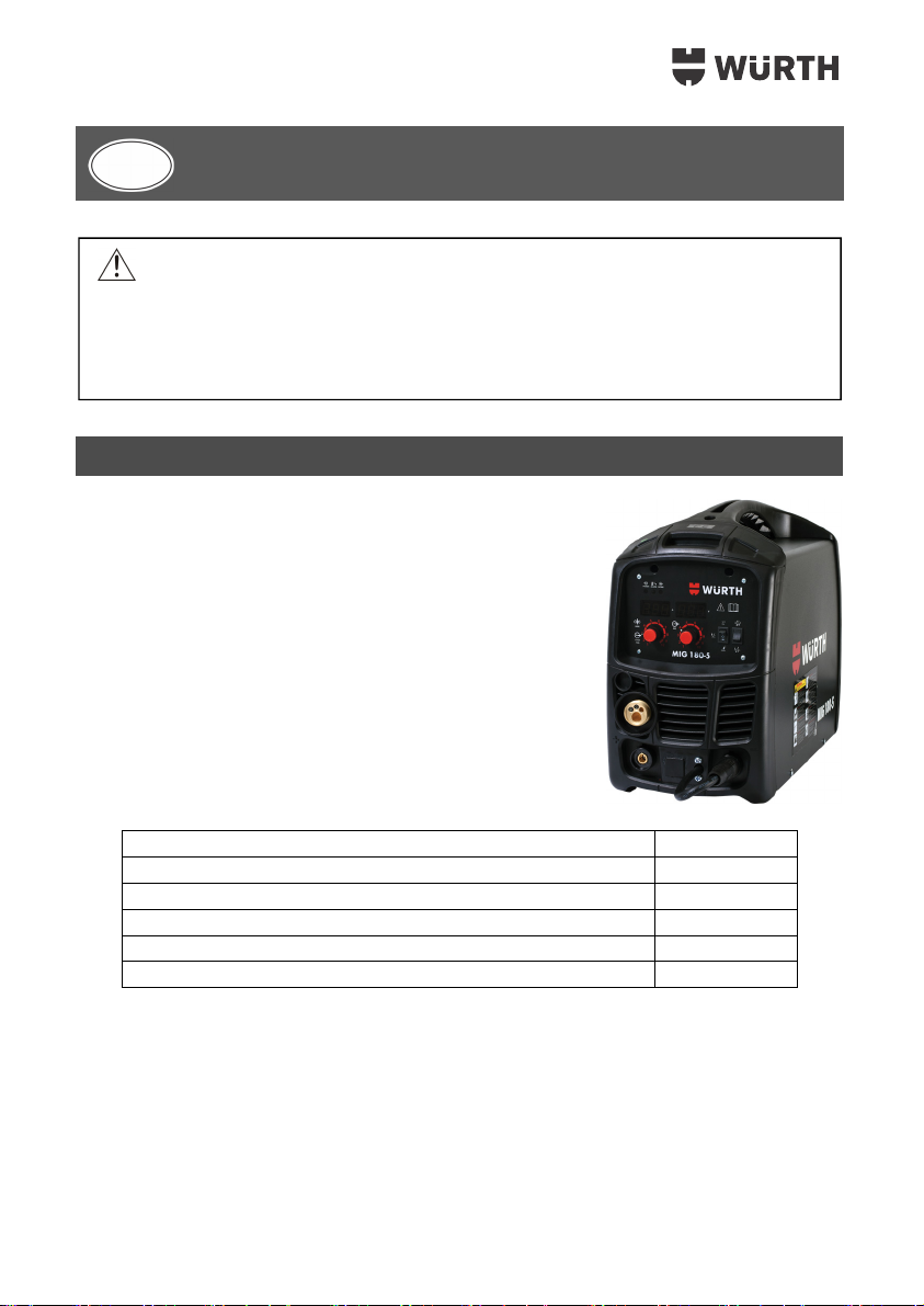
THE MIG WELDING OPERATION
1. Main controls
Power switch – The power switch supplies electrical current to the welder. Whenever the power
switch is in the ON position, the welding circuit is activated. ALWAYS turn the power switch to the OFF
position and unplug the welder before performing any maintenance.
Voltage selector – The voltage selector controls the welding heat. This unit has infinite voltage
control. Refer to the label inside the welder side door for recommended voltage selector settings
required for your welding job.
Wire speed control – The wire speed control adjusts the speed at which the wire is fed out of the
welding torch. The wire speed needs to be closely matched (tuned-in) to the rate at which it is being
melted off. Some of the few things that affect wire speed selection are the type and wire diameter being
used, the heat setting selected, and the welding position to be used.
Note: The wire will feed faster without welding arc established. When an arc is being drawn, the wire
speed will slow down.
2. Holding the torch
The best way to hold the welding torch is the way that feels most comfortable to you. While practicing
to use your new welder, experiment holding the torch in different positions until you find the one that
seems to work best for you.
3. Positioning the torch onto the workpiece
There are two angles of the torch nozzle in relation to the workpiece that must be considered when
welding.
3.1. Angle A can be varied, but in most cases the optimum angle will be 60 degrees, the point at
which the torch handle is parallel to the work piece. If angle A is increased, penetration will
increase. As angle A is decreased, the penetration is decreased as well.

12
3.2. Angle B can be varied for two reasons: to improve the ability to see the arc in relation to the weld
puddle and to direct the force of the arc.
4. Distance from the workpiece
If the nozzle is held off the work piece, the distance between the nozzle and the workpiece should be
kept constant and should not exceed 6 mm or the arc may begin sputtering, signaling a loss in welding
performance.
5. Tuning in the wire speed
This is one of the most important parts of MIG welder operation and must be done before starting each
welding job or whenever any of the following variables are changed: heat setting, wire diameter, or
wire type.
WARNING
Exposure to a welding arc is extremely harmful to your eyes and skin!
Prolonged exposure to the welding arc can cause blindness and burns. Never strike an arc or begin
welding until you are adequately protected. Wear flameproof welding gloves, a heavy long sleeved
shirt, trousers with no cuffs, high topped shoes, and an ANSI approved welding helmet.
5.1. Connect the Ground Clamp to a scrap piece of the same type of material which you will be
welding. It should be equal to or greater than the thickness of the actual workpiece, and free of
oil, paint, rust, etc.
5.2. Select the heat setting. Refer to set up chart.
5.3. Hold the torch in one hand, allowing the nozzle to rest on the edge of the workpiece farthest
away from you, and at an angle similar to that which will be used when welding. (See HOLDING
THE TORCH if you are uncertain of the angle at which you will be welding).
5.4. With your free hand, turn the Wire Speed Dial to maximum and continue to holding the knob.
Angle B
Angle A

13
5.5. Lower your welding helmet and pull the trigger on the torch to start an arc, then begin to drag the
torch towards you, while simultaneously turning the Wire Speed Dial counter-clockwise.
5.6. LISTEN! While decreasing wire speed, the sound that the arc produces will change from a
sputtering to a high-pitched buzzing sound and then will begin sputtering again if you decrease
the wire speed too much. The position of the wire speed adjustment knob where the high-pitched
buzzing sound is achieved represents the correct setting. You can use the wire speed control to
slightly increase or decrease the heat and penetration for a given heat setting by selecting higher
or lower wire speed settings. Repeat this tune-in procedure if you select a new heat setting, a
different wire diameter, or a different type of welding wire.
6. Welding Techniques
WARNING
Exposure to a welding arc is extremely harmful to your eyes and skin!
Prolonged exposure to the welding arc can cause blindness and burns. Never strike an arc or begin
welding until you are adequately protected. Wear flameproof welding gloves, a heavy long sleeved
shirt, trousers without cuffs, high topped shoes and an ANSI approved welding helmet.
Electric shock can kill!
To prevent ELECTRIC SHOCK, do not perform any welding while standing, kneeling, or lying directly
on the grounded work.
6.1 Moving the torch
Torch travel refers to the movement of the torch along the weld joint and consists of two action elements:
Direction and Speed. A solid weld bead requires that the welding torch be moved steadily and at the
right speed along the weld joint. Moving the torch too fast, too slow, or erratically will prevent proper
fusion or create a lumpy, uneven bead.
Travel direction is the direction the torch moved along the weld joint in relation to the weld puddle.
The torch is either PUSHED into the weld puddle or PULLED away from the weld puddle.
For most welding jobs you will pull the torch along the weld joint to take advantage of the greater weld
puddle visibility.
Travel speed is the rate at which the torch is being pushed or pulled along the weld joint. For a fixed
heat setting, the faster the travel speed, the lower the penetration, and lower and narrower the finished
weld bead. Likewise, the slower the travel speed, the deeper the penetration and the higher and wider
the finished weld bead.
Push Pull
Weld
Puddle

14
6.2 Types of weld beads
As you become more familiar with your new welder and better at laying some simple weld beads, you
can begin to try some different weld bead types.
The STRINGER BEAD is formed when torch is traveling in a straight line while keeping the wire and
nozzle centered over the weld joint (See the following figure).
The WEAVE BEAD is used when you want to deposit metal over a wider space which wouldn't be
possible using a stringer bead (without transfer oscillation). It is made by weaving electrode from side
to side with slight hesitation at the end of each oscillation while moving it longitudinally. That is the best
way to improve weld penetration.
6.3 Welding position
Flat position is easiest of the welding positions and is most commonly used. It is best if you can weld
in the flat position if at all possible as good results are easier to achieve.
Horizontal position is performed very much the same way as the flat weld except that the angle B
(see "HOLDING THE TORCH") is such that the wire, directed more towards the metal above the weld
joint is to help prevent the weld puddle from running downwards while still allowing slow enough travel
speed. A good starting point for angle B is about 30 degrees DOWN from being perpendicular to the
workpiece.

15
Vertical position is easier for many people since it involves pulling the torch from top to bottom. It
can be difficult to prevent the puddle from running downwards. Pushing the torch from bottom to top
may provide better puddle control and allows slower rates of travel speed to achieve deeper
penetration. When vertical welding, angle B (see "HOLDING THE TORCH") is usually always kept at
zero, but angle A will generally range from 45 to 60 degrees to provide better puddle control.
Overhead position is the most difficult welding position. Angle A (see "HOLDING THE TORCH")
should be maintained at 60 degrees. Maintaining this angle will reduce the chances of molten metal
falling into the nozzle. Angle B should be held at zero degrees so that the wire is aiming directly into
the weld joint. If you experience excessive dripping of the weld puddle, select a lower heat setting.
Also, the weave bead tends to work better than the stringer bead.
6.4 Multiple pass welding
Butt Weld Joints. When butt welding thicker materials, you will need to prepare the edges of the
material to be joined by grinding a bevel on the edge of one or both pieces of the metal being joined.
When this is done, a “V” groove is created between the two pieces of metal that will have to be closely
welded. In most cases more than one pass or bead will need to be laid into the joint to close the “V”
groove.
Laying more than one bead into the same weld joint is known as a multiple-pass weld.
The following figure show the sequence for laying multiple pass beads into a single “V” butt joint.
First or
Root Pass
Second
pass
T
hird
pass
Finished
Weld

16
Note:
When using self-shielding flux-core wire it is very important to thoroughly chip and brush the
slag off each completed weld bead before making another pass or the next pass will be of poor quality.
Fillet Weld Joints. Most fillet weld joints, on metals of moderate to heavy thickness, will require
multiple pass welds to produce strong joint. The illustrations in Figure 19 show the sequence of laying
multiple pass weld beads into a T fillet joint and a Lap fillet joint.
6.5 Spot welding
There are three methods of spot welding: Burn-Through, Punch and Fill, and the Lap Spot type. Each
method has advantages and disadvantages depending on the specific application as well as the
personal preference.
1. The Burn Through method welds two overlapped pieces of metal together by burning through
the top piece and into the bottom piece. When using the Burn-Through method, larger wire diameters
tends to work better than smaller diameters. Wire diameters that tends to work best, using the burn-
through method are 0.9 mm self-shielding flux-core wires. Do not use 0.75 mm self-shielding flux
core wires when using the burn-through method unless the metal is VERY thin or excessive filler metal
build-up and minimal penetration is acceptable. Always select the HIGH heat setting with the burn-
through method and tune in the wire speed prior to making any spot welds.
2. The Punch and Fill method produces a weld with the most finished appearance of the three
spot weld methods. In this method, a hole is punched or drilled into the top piece of metal and the
arc is directed through the hole to penetrate into the bottom piece. The puddle is allowed to fill up
the hole leaving a spot weld that is smooth and flushed with the weld surface established on the top
piece. Select the right wire diameter, heat setting, and tune in the wire speed as if you were welding
the same thickness material with a continuous bead.
3. The Lap Spot method directs the welding arc to penetrate both the bottom and the top piece at
the same time, right along each side of the lap joint seam. Select the right wire diameter, heat setting,
Lap Joint Welded
in Three Passes
„T“ Joint in
Three Passes
Punch and fill Burn through Lap spot

17
and tune in the wire speed as if you were welding the same thickness material with a continuous
bead.
6.6 Spot welding instructions
1. Select the wire diameter and heat setting recommended above for the method of spot welding you
intend to use.
2. Tune in the wire speed as if you were going to make a continuous weld.
3. Hold the torch nozzle completely perpendicular to and about 6 mm off the work piece.
4. Pull the trigger on the torch and release it when it appears that the desired penetration has been
achieved.
5. Make practice spot welds on scrap metal, varying the length of time you holding the trigger, until a
desired spot weld is achieved.
6. Make spot welds on the actual work piece at desired locations.
7. Electrode
The welding electrode is a rod coated with a layer of flux. When welding, electrical current flows
between the electrode (rod) and the grounded metal workpiece. The intense heat of the arc between
the rod and the grounded metal melts the electrode and the flux.
8. Selecting the proper electrode
There is no golden rule to determine the exact electrode or heat setting required for every particular
situation. The type and thickness of metal and the position of the workpiece rule the electrode type and
the amount of heat needed during welding process. Heavier and thicker metals require more
amperage. It is best to practice your welds on scrap metal which matches the metal you intend to work
with, in order to define correct heat setting as well as make appropriate electrode choice. Please
observe some following helpful troubleshooting tips to determine if you are using a correct electrode.
1. When electrode of proper size is used
a. The bead will lay smoothly over the workpiece
without ragged edges.
b. The base metal puddle will be as deep as the bead
that rises above it.
c. The welding operation will make a crackling sound
similar to the sound of eggs frying.
2. When too thin electrode is used
a. The weld bead will be too high and irregular
b. The arc will be difficult to maintain
3. When too thick electrode is used
a. The arc will burn through thin metals
b. Occurrence of the weld bead undercutting
c. The bead will be flat and porous
d. Rod might get freezed or sticked to the workpiece
Note: Rate of travel over the workpiece also affects the weld. To ensure proper penetration and enough
rod deposit, the arc must be moved slowly and evenly along the weld seam.

18
Operation
1. Setting the adequate amperage
It is capable of welding with 2.5mm, 3.2mm and 4mm electrodes.
There is no golden rule that determines the exact amperage required for every particular situation. It is
best to practice your welds on scrap metal which matches the metals you intend to work with in order
to determine correct settings for your job. The electrode type and the thickness of the metal workpiece
define the amount of heat needed in the welding process. Heavier and thicker metals require more
current (amperage), whereas lighter and thinner metals require less current (amperage).
2. Welding techniques
The best way to teach yourself how to weld is with short periods of practice at regular intervals. All
practice welds should be done on scrap metal that can be discarded. Do not attempt to make any
repairs on valuable equipment until you are satisfied with yourself and your practice welds are of good
appearance and free of slag or gas inclusions.
2.1 Holding the electrode
The best way to grip the electrode holder is the way that feels most comfortable to you. To position the
electrode on a workpiece when striking the initial arc, it is necessary to hold the electrode perpendicular
to the workpiece. Once the arc is started the angle of the electrode in relation to the workpiece should
be between 10 and 30 degrees. This will allow good weld penetration, with minimal spatter.
2.2 Striking the arc
WARNING
EXPOSURE TO A WELDING ARC IS EXTREMELY HARMFUL TO THE EYES AND SKIN.
• Never strike an arc or begin welding until you have adequate protection.
• Wear flameproof welding gloves, heavy long-sleeved shirt, cuffless trousers, high-topped shoes and
a welding helmet or shield.
Scratch the work piece with the end of electrode to start arc and then raise it quickly to about 3 mm
gap between the rod and the workpiece. Please observe the following picture:
It is important that the gap is maintained during the welding process and it should be neither too wide
or too narrow. If it is too narrow, the rod will stick to the workpiece. If it is too wide, the arc will be
extinguished. It takes a a lot of practice to maintain the gap. Beginners may usually get sticking or arc
extinguishing. When the rod sticks to the workpiece, gently rock it back and forth to separate it from
the workpiece. If you don't, the short circuit occurs, which leads to welder overload. A good arc is

19
accompanied by a crisp, cracking sound. The sound is similar to that made when frying eggs. To lay a
weld bead, only 2 movements are required; downwards and in direction of the weld to be laid, as
shown in the following picture:
2.3 Types of weld beads
The following paragraphs discuss the most commonly used arc welding beads. The stringer bead is
formed when electrode is traveling in a straight line while kept centered over the weld joint.
The weave bead is used when you want to deposit metal over a wider space which wouldn't be possible
using a stringer bead (without transfer oscillation). It is made by weaving electrode from side to side
with slight hesitation at the end of each oscillation while moving it longitudinally. That is the best way
to improve weld penetration.
2.4 Welding position
Flat position is the easiest of all welding positions and is most commonly used. It is best if you can
weld in the flat position if at all possible since good results are easier to achieve.

20
The Horizontal Position is performed very much the same way as the flat weld except that the
angle is different such way that the electrode, and therefore the arc force, is directed more toward the
metal above the weld joint. This more direct angle helps prevent the weld puddle from running
downwards while still allowing slow enough travel speed to achieve good penetration. A good starting
point for your electrode angle is about 30 degrees DOWN from being perpendicular to the workpiece.
2.5. Judging a good weld bead
When the trick of establishing and holding an arc has been learned, the next step is to learn how to
run a good bead. The first attempts in practice will probably fall short of acceptable results. Arc too
long will be held or the travel speed will vary from slow to fast. (Please observe the following picture).
A. Weld speed is too fast.
B. Weld speed is too slow.
C. Arc is too long.
D. Ideal weld.
A solid weld bead requires the electrode to be moved slowly and steadily along the weld seam. Moving
the electrode rapidly or erratically will prevent proper fusion or create a lumpy, uneven bead. To
prevent ELECTRIC SHOCK, do not perform any welding while standing, kneeling, or lying directly on
the grounded workpiece.

21
2.6 Finishing the bead
As the coating on the outside of the electrode burns off, it forms an envelope of protective gasses
around the weld. This prevents air from reaching the molten metal and creating an undesirable chemical
reaction. However, coating burning forms slag. The slag formation appears as an accumulation of dirty
metal scale on the finished weld. Slag should be removed by striking the weld with a chipping hammer.
3.
The LIFT TIG welding method
3.1 Accessory
Switch off the welder. Remove mains plug from the wall socket.
Connect the ground cable to the positive dinse socket and screw it tight. Connecct the end of the ground
cable (earth clamp) to the workpiece. Connect the torch cable to the negative dinse socket and screw
it in clockwise direction. Tighten the torch gas hose adaptor which connects the shielding gas cylinder.
Insert the mains plug into the mains socket.
3.2 The torch pilot arc
Warning! Turn on the welder. Welding torch's tungsten electrode is already charged. The tungsten
electrode should not touch anything. This series TIG welding machine needs contact striking to produce
the arc.
How to strike the arc method is explained in the following steps:
A. Open the built-in TIG torch gas valve. Place the gas nozzle so that the tungsten electrode and the
workpiece are separated 2~3 mm.
B. Slowly lift the welding torch to cause the tungsten electrode to get into contact with a workpiece.

22
C. Lift the welding torch to the normal position to initiate the arc and start welding.
Table of contents
Languages:
Other Würth Welding System manuals

Würth
Würth PINPULLER SPOT User manual

Würth
Würth POWERCUT 70 User manual

Würth
Würth MIG/MAG 250 User manual

Würth
Würth ESI 160 User manual

Würth
Würth PinPuller User manual

Würth
Würth EWI 160 User manual

Würth
Würth WIG 180 DC User manual

Würth
Würth ESI 200 Quick guide

Würth
Würth WIG 180 DC Quick guide

Würth
Würth master ESI 150 User manual