wallas M40 Manual

T0209

T0209

M40
1 / ENGLISH
INSTALLATION INSTRUCTIONS
Under 1500 m
Over 1500 m
SPACE HEATER LOCATION
1.Free distance from the surrounding walls as
shown in fig. 1.
2.The spaces between the walls must be kept
clean and free from dust, litter and foreign
objects.
3.The air inlets of the lower part of the heater
jacket at the front, sides and back must be
kept free from objects and hindrances pre-
venting air intake.
4.There must not be any surfaces, construc-
tions or objects presenting fire hazard or pre-
venting the heat flow directly above the hea-
ter closer than 1 metre from the top of the
heater. Fig. 1.
5.The heater must be properly fastened by
screws to the floor or to its foundation casing,
which is also fastened to the floor. The equip-
ment must be in vertical position. Fig. 2.
6.The heater must be placed so that no water
can drip, flow or splash into it.
7.The maximum lenght of uninsulated exhaust
pipe is 3 m, insulated 6 m.
8.If needed notice the change of air density by
changing mountain parameters on the elec-
tronics (PCB), when the heater is situated
over 1500 m altitude above the sea level for
example on an arctical hill.
Fig. 1.
Fig. 2.
Fig. 3.
T0209

M40
2 / ENGLISH
TANK LOCATION
1.The fuel tank is good to be placed beneath
the heater foot. Fig. 4. (The surface of the
liquid fuel must be beneath the foot). When
the liquid surface is above the heater foot, a
magnetic valve is recommended to install
near the tank end.
2.The fuel tank may be installed into its foun-
dation casing or outside, for example, into
the basement of the house or inside a sui-
table, protective casing. The fuel tank and
hose must be protected from direct sunlight.
3.The fuel hose inlet through the constructions
must be protected by a metal pipe.
4.The basic length of the fuel hose is 3 met-
res. It may be extended by using a 2-metre
extension hose which makes the total hose
length 5 metres. The hoses are linked by
using threaded quick connectors. Fig. 4
shows the maximum limits of the installation.
BATTERY LOCATION
1.The equipment contains 4 metres of electri-
cal wire with a thickness of 4 mm2. In case
the distance between the battery and equip-
ment is 6 metres, the cabel thickness must
be 6 mm2and so on.
2.The electrical wires must be protected by pla-
cing a 15 A fuse at the battery end of the po-
sitive cable of the electrical wire.
3.The battery should be located so that there
will not be any danger when the battery is
charged or used.
N.B. The voltage must be primarily taken di-
rectly from the battery, not from the control unit
of the solar battery. This will ensure that the
system bears the ignition current and does not
receive excess voltage. Contact your system
supplier for further details.
INSTALLATION HOLES
1.Choose the place for the heater. See instruc-
tions above.
2.Exhaust gases shall always be led out. If de-
sired, they can be led out directly through the
wall. In this case, the combustion air is also
taken from outside, which contributes to ba-
lancing the pressure fluctuations caused by
the wind. See the separate leaflet describing
installation alternatives.
3.Make holes through the wall according to the
dimensions given in fig. 5. In the case of duct
installation, the hole for exhaust gas (diame-
ter 120 mm) shall be dimensioned in its cor-
rect location. Make a separate hole for fresh
air (diameter 50 mm) in the fresh air duct or
through the floor. (For sizes of the holes, see
fig. 5). As far as a duct installation is con-
cerned, the fire ventilation air may also be
taken from indoors.
INSTALLATION INSTRUCTIONS
Fig. 5.
Fig. 4.
T0209

M40
3 / ENGLISH
8.The equipment is ready for use after the
electrical wire and fuel hose have been con-
nected.
INSTRUCTIONS FOR INSTALLATION IN
THE DUCT
1.Cut the hoses, insulating channels and pro-
tecting plates so that they each the inner sur-
face of the duct.
2.Fasten the hoses to the heater by using
clamps. The exhaust pipe must be tightened
properly by using power press binding.
3.Mount the heater to its place.
4.Tighten the joint between the exhaust pipe
and the duct by using acrylic mass.
5.The equipment is ready for use after the
electrical wire and fuel hose have been con-
nected.
N.B. When taking the combustion air from un-
der the floor, make sure that the base floor has
sufficient ventilation. Install a protective spiral
at the end of the hose.
- In a high (over 5 metres) and large (cross-
sectional surface over 15 x 15 cm) duct, ex-
haust gases are cooled down so that the
moisture in them is condensed, thus causing
the chimney to decay, as well as decreasing
the draught. Therefore, a brick duct should
be lined with stainless steel pipe (diameter
50-70 mm), as well as filling the space bet-
ween the pipe and duct by, for example, ex-
panded clay.
- Air for fire ventilation cannot be taken from
the same duct through which exhaust gases
are discharged.
INSTRUCTIONS FOR INSTALLATION
THROUGH THE WALL
1.Install the covering plates on the wall and tigh-
ten the joint by acrylic mass. Put a plate with
8 holes on the outer wall.
2.Cut the ducts and insulating channels as
shown in fig. 6 (items A and B).
ACut them so that the insulation will be 10
mm outside the wall (the insulating plate
shall also be 10 mm outside the wall).
BCut them so that the ducts will be 40-45
mm outside the wall.
3.Fasten the ducts to the heater by using hose
clamps. The exhaust gas pipe must be tigh-
tened properly by using power press binding.
4.Mount the heater and its ducts to their pla-
ces.
5.Mount the insulating channels and protecti-
ve plate from the outside. Cut small tongues
on one of the protective plates (Fig. 6, item
C) and install this one with the tongues
against the covering plate on the outer wall.
6.Install the exhaust gas discharge casing and
the shroud (protection against contact) so
that the pipe ends reach the limit stops of the
casing. Tighten the joint between the casing
and covering plate by using acrylic mass.
7.Fasten the heater on the floor or foundation
casing by screws.
INSTALLATION INSTRUCTIONS
Fig. 6.
Covering plate
Insulating plate
Covering plate
Insulating
channels
Hose
clamps
Discharge casing
Shroud (protection
against contact)
T0209

M40
4 / ENGLISH
OPERATION INSTRUCTIONS
FUEL
The following alternative fuels can be used in
the space heater :
Remember to take operating temperature
into account while choosing the fuel type.
Following temperature limits are for refer-
ence only. Check temperature limits from
your local fuel supplier.
- Furnace oil / Diesel oil, summer quality, am-
bient temperature must be higher than –5°C
- Furnace oil / Diesel oil, winter quality, ambi-
ent temperature must be higher than –24°C
- Furnace oil / Diesel oil, arctic quality, ambi-
ent temperature must be higher than –40°C
- Paraffin (kerosene), ambient temperature
must be higher than –40°C
If ambient temperature is lower than recom-
mended fuel can be waxing (fuel becomes
cloudy). Wax can block fuel filter and pump.
Wax won’t dissolve until the ambient tempera-
ture is clearly over 0°C. In winter conditions
arctic quality or paraffin (kerosene) must be
used.
The less aromatic substances are contained
in the fuel, the less crust will be formed. The
aromatic substances content in normal fuel oils
is about 35 - 40%, in dyed city-diesel oils (for
example, Tempera 3G and 5G) about 20%. The
aromatic substances content of paraffin is
about 0.5%, and consequently, almost no crust
is formed during combustion.
THE FIRST START-UP
1.Press the starting switch on: position 1.
2.The device does not necessarily start at the
first time, as the fuel hose is empty. In such a
case, the red light begins to blink after about
4.5 minutes from the start-up. Press the star-
ting switch to position 0. The device cannot
be re-started until both signal lights are out
(after-ventilation period). Start again after the
signal lights have gone out. The red signal
light comes on after about 2.5 - 4 minutes
from the start-up, and then the combustion is
normal.
N.B. Do not start at the same time as the bat-
tery will be charged from a generator or batte-
ry charger (danger of over voltage)
NORMAL START-UP
1. Press the starting switch on: position I. The
red signal light comes on after about 2.5 - 4
minutes from the start-up, and then the com-
bustion is normal. After the start-up stage
(about 5 minutes), the heater’s output re-
mains at the set value.
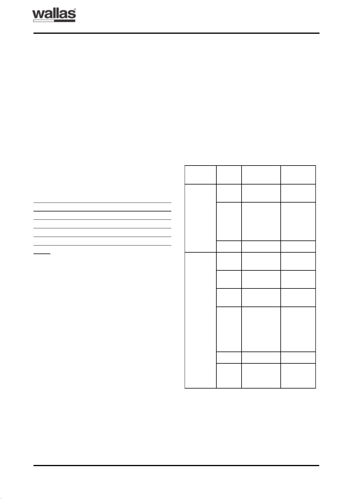
SIGNAL LIGHTS OF M40 CONTROL
PANEL
* Opening of the locking:
1 Switch ON the heater (blinking of locking).
2 Disconnect the main current wire of the heater (hea-
ter (blinking) switches off).
3 Reconnect the main current wire (yellow LED lights
1 - 3 second).
4 When yellow LED dies switch OFF the heater.
ruoloC
DELfo
gniknilB
lavretni gninaeM
noitcnuF
wolleY sthgiL
.ylsuounitnoc notnerruC
deR sthgiL
.ylsuounitnoc
,thgilrenruB
nehw
noitsubmoc
nugebsah
.yllamron
deR s52,0 gniloocretfA
;eruliaF
eruliaf
langis
5sekat
setunim
retfadna
ylnotaht
DELder
.gniknilbsi
wolleY s2 gulpwolG
eruliaf
wolleY s2ajs521,0 nafrenruB
eruliaf
wolleY s52,0 rednU
egatloV
wolleY
derdna s521,0
;gnikcoL
ecapseht
siretaeh
gnikcol
2retfa
*.tratsdeliaf
deR s52,0 taehrevO
deR s03
retfasthgiL
eruliaf
.langis
T0209

M40
5 / ENGLISH
TECHNICAL DETAILS
CHECK-LIST AT SERVICE FAILURES
The fuel is not moving: The movement can
be checked by lifting the suction hose out of
the tank for a few seconds; there will be an air
bubble moving with the fuel.
- Check the tightness of the joint: if necessary,
make the joint tighter.
- Check the hose: replace a leaking hose with
a new one.
- Make sure that the pump receives voltage;
the pumping sound or voltage variation when
measuring the voltage.
No voltage is received: the yellow light is not
on.
- Check the charging of the battery.
- Check the connections of the battery or po-
wer-supply unit.
- Check if the automatic fuse has tripped and
come up, press it down if necessary. Check
the main fuse connected to the electric con-
ductor and replace it if necessary.
Under-voltage: the yellow light is blinking.
- Charge the battery or replace it with a more
powerful one.
- Replace the electric conductors with thicker
ones; see installation instructions.
Too much fuel is received: the heater is over-
heated and cuts off its function by itself.
- Check that the fuel surface of the tank is be-
low the lower surface of the heater
- The exhaust gas or fire ventilation hose is
blocked.
- Remove obstacles and blockages
Fuel and voltage is received normally, but
the device will not start:
- Check through the inspection port whether
the glow plug is glowing at start-up, change
it if necessary.
- Check the fuel composition and if there is any
suspicion that water may have condensed
into the tank, remove the water; see mainte-
nance instructions.
N.B. The device cannot be re-started until the
red and yellow signal lights have gone out.
If necessary, contact the nearest Wallas servi-
ce or your supplier.
Fuel:
Furnace oil / Diesel oil (anti-freezing proper-
ties according to the operating conditions) or
paraffin (kerosene)
Fuel consumption:
M40: 0.16 - 0.4 litres/hour = 3.8 – 9.6 litres/
day
Thermal power:
M40: 1600 – 4000 W
Power adjustment:
Stepless manual adjustment or room thermos-
tat
Starting:
By manual switch or automatic, weekly timer
(additional equipment) or by remote control
starter (additional equipment)
Operating voltage:
12 V. Power source: battery or Wallas power-
supply apparatus equipped with a 12 V/15Ah
mini battery.
Current consumption:
0.2 – 0.4 A = 4.8 – 9.6 Ah/day
Heater current 8 A for 4.5 minutes after start-
up.
Dimensions and weight:
M40 730 x 440 x 240 mm / 25.5 kg
OPERATION INSTRUCTIONS
T0209

M40
6 / ENGLISH
SERVICE INSTRUCTIONS
B
A
The fuel contains aromatic substances that
form crust at the bottom of the burner. The
speed of encrustation depends on the quality
of the fuel and the output of the heater, and
consequently, the need for service may be va-
rying. During servicing, the crust will be remo-
ved from the burner and the fuel needle and
bottom carpet will be replaced by new ones, if
necessary.
Cleaning of the burner
Lift the protective grating of the heater. Open
the front wall of the heater by lifting the wall
upwards.After this, the front wall can be pulled
out. The front wall is fastened with tongues to
the screws on the sides, loose the screws, if
necessary.Arrows in fig. 7. Detach the protec-
tive plate of the plinth by undoing the screw in
the middle. See the circle in fig. 7. Pull the pro-
tective plate forwards and lift it up.
temperature sensor carefully. If the packing has
become brittle, it must be replaced with a new
one. If the glow plug is damaged, replace the
old plug with a new one. Fig. 9 shows an intact
glow plug and a typical glow plug in short cir-
cuit.Aglow plug does not usually look different
if there is a cut-off.
Unscrew the fuel needle clamp and pull the fuel
needle carefully out by rotating it. See the ar-
row in fig. 8. The fuel needle is equipped with
a locking ring that defines the depth to which
the needle is installed. In model M40 the instal-
lation depth is 50 mm. If the fuel needle is
blocked, replace it with a new needle by pul-
ling the fuel hose out of the upper clamp of the
pump and install the hose for the new needle.
See the circle in fig. 8. Undo the 5 fixing sc-
rews and one distance screw on the combus-
tion chamber cover. Detach the combustion
chamber cover.
The packing inside the combustion chamber
cover must be intact as shown in fig. 10. De-
tach the burner assembly from the heater by
pulling out the spring that holds it in position.
See fig. 11.
Detach the screw and clamp of the tempera-
ture sensor and the corresponding glow plug
clamp from the combustion chamber cover.
See fig. 8. Pull the glow plug and temperature
sensor carefully out; do not pull from the wires
of the parts. Remove the white packing of the
Glow plug Temperature sensor
Fig. 8: How to detach the temperature sensor, glow
plug and fuel needle.
Fig. 9: Intact glow plug (above) and damaged glow
plug in short circuit (below).
Fig. 7: M40 heater.
T0209

M40
7 / ENGLISH
Fig. 12 shows the burner parts of M40. De-
tach the heat radiator by pressing the locking
tongue towards the burner cylinder wall and by
inclining the heat radiator. Fig. 13.
Crust is mainly formed on the bottom of the
burner cylinder. Scratch the crust carefully off,
for example, by using a screwdriver. If neces-
sary, also clean the walls of the burner cylinder
and the heat radiator. It is advisable to replace
the bottom carpet in position when cleaning
the cylinder. Fig. 14. The bottom carpet acts
as a heat insulator of the burner cylinder du-
ring ignition, and consequently, the carpet must
be intact at least under the glow plug.
The burner is reassembled in the same way
as it was demounted, but in the reverse order.
When assembling the burner cylinder make
sure that the heat radiator is locked into its
position. To secure the locking, tap the burner
upside down, which makes the heat radiator
come off from its clamps, if it is not locked.
When installing the burner assembly move it
back and forth to make it settle tightly into the
heat exchanger. See the arrows in fig. 15. Turn
the burner to its position and push the spring
under the burner. Fig. 15.
Fig. 12: M40 burner parts.
Heat radiator
Burner cylinder
Temperature
sensor pipe
Fuel needle hole
Glow plug hole
Fig. 13: Detaching the heat radiator.
Fig. 14: Burner cylinder.
Bottom carpet.
Crust
Fig. 11: Detaching the burner.
Fig. 10: M40 burner chamber opened.
Fig. 15: Installation of the burner.
SERVICE INSTRUCTIONS
T0209

M40
8 / ENGLISH
SERVICE INSTRUCTIONS
The fuel needle is in correct position, when it
is bent to the right (towards the fuel pump). To
prevent the burner chamber cover from
sticking, it is advisable to apply heat resistant
grease on the fixing screws.
Checking the function of the heater
The functioning of the burner must always be
checked after the heater has been serviced.
- Start the heater and let it burn for 15 minutes.
- Check through the inspection window that the
heat radiator is glowing red and that the fla-
me is burning smoothly.
- There should be many separate flames with
smooth edges in the burner. The flame may
be either all blue or blue and yellow.
- If the flame is burning smoothly and the heat
radiator is red, the burner and heater are fun-
ctioning normally.
- If the flames cannot be discerned from each
other or if the flames are all yellow or entang-
led, there are air leakages in the burner. In
this case, reopen the heater and check all
the burner joints for air leakages.
- An unstable burner flame during operation is
probably a sign that the burner needs clea-
ning.
Fuel system and electronics card
Measuring the fuel feed
If any parts of the fuel system have been repla-
ced, the fuel feed of the heater must be
checked by measuring it.
1. Start the heater at full capacity.
2. Pour some fuel into a measuring glass, e.g.
50 ml. Place the fuel pipe into the measuring
glass and start the clock at the same time.
3. Take the fuel pipe out of the measuring glass
after six minutes.
4. Multiply the amount of fuel in millilitres con-
sumed in six minutes by ten to obtain the fuel
consumption per hour. Normal fuel consump-
tion at full capacity is 0.4 ± 0.02 l/h.
5. Compare the measured value with the nor-
mal value; if there are differences, adjust the
fuel feed by turning the trimmer shown in fig.
17.
At the same time, it is easy to check the po-
wer adjustment of the heater.
Fig. 16: Fuel system parts.
Fuel feed
pipe
Fuel pump
Male connector for suction hose
Fuel suction hose
Filter
head
Protecti-
ve spiral
T0209

M40
9 / ENGLISH
Fig. 17: Electronics card connections.
Fuel feed trimmer
Connection to
thermostat and
remote control
Fuse,
slow 5 A
SERVICE INSTRUCTIONS
T0209

M40
10 / ENGLISH
b.
ACCESSORIES´ CONNECTIONS
Fig. 18: Connecting a 4420 GSM remote control to the heater.
Alarm
Temperature sensor
Fig. 19. Connecting a solenoid valve to the heater.
Fig. 20. Connecting a room thermostat (a) and a weekly timer (b).
a.
The short-circuit loop shall be eliminated.
T0209

M40
1 / SVENSKA
MONTERINGSANVISNINGAR
Värmeaggregat Wallas M40: Monterings-, bruks- och underhållsanvisningar / Sverige,
Finland
Notera i Sverige; Anvisningarna är godkända av SP med nr E12810. Typgodkännandennr. för M40 nr SP 585 K.
För att försäkra sig om en riktig installation, skall skorstensfejare i det berörda distriktet kontaktas. Före användin-
gen skall alla anslutningars (rökgaser, förbränningsluft, bränsle, rökgasrörets mynning) täthet kontrolleras.
Figur 3.
Under 1500 m Över 1500 m
Tabell 1: Minsta avstånd (m, linjär interpolation) i Sve-
rige.
gatnitfulsgninnärbröF
:kramrevö m0,1
:gninnymsterörsagvA
kramnavO m1,1
trabsgninppönårF
retsnöf m0,1
gninppösnoitalitnevnårF m5,1
rrödvanadisrellenavO m5,0
PLACERING AV VÄRMEAGGREGAT
1.Fritt avstånd till omgivande väggar enligt fi-
gur 1. Övriga minimiavstånd i Sverige enligt
tabell 1.
2.Utrymmena mellan aggregat och väggar skall
hållas rena och fria från damm, skräp och
främmande föremål.
3.Luftingsöppningarna på framsidan, sidorna
och baksidan av aggregatets hölje (dess
nedre del) skall hållas fria från föremål och
hinder som hindrar ett fritt luftintag.
4.Det får inte finnas ytor, konstruktioner eller
föremål som är brandfarliga eller hindrar vär-
meströmningen rakt ovanför värmeaggrega-
tet inom ett avstånd av 1 m från aggregatets
övre yta. Se figur 1.
5.Värmeaggregatet skall fästas stabilt vid gol-
vet eller stativhöljet med skruvar. Även sta-
tivhöljet fästs vid golvet.Aggregatet skall stå
i lodrätt läge. Se figur 2.
6.Värmeaggregatet skall placeras så att vat-
ten inte kan droppa, rinna eller stänka på det.
7.Obs! Den maximala längden för ej isolerat
avgasrör är 3 meter, för isolerat 6 m.
8.När aggregatet används på högre altituder,
t.ex. i fjällen över 1500 m kan luftdensitetens
ändring tas hänsyn till genom att efter beho-
vet koppla bergsparameter på elektronikkor-
tet.
Figur 2.
Figur 1.
T0209

M40
2 / SVENSKA
Figur 5.
Figur 4.
PLACERING AV TANK
OBS! Bränsletank skall vara utförd och place-
rad enligt gällande föreskrifter (statens indust-
riverks kungörelse med tillämpningsföreskrif-
ter till förordningen om brandfarliga varor SIND-
FS 1981:2 med ändring SÄIFS 1989:12).
1.Bränsletanken placeras bäst under botten av
värmeaggregatet. Se figur 4. (Bränslets yt-
nivå måste ligga under foten.) Om bränsleni-
vån är högre än kaminens botten, rekom-
menderas montering av en magnetventil på
bränsleledningen.
2.Bränsletanken kan placeras i stativhöljet (se
fig. 2) eller externt, t.ex. i husets krypgrund
(se fig. 4) eller i en lämplig skyddslåda. Skyd-
da tanken och bränsleröret mot direkt soll-
jus.
3.Genomföringen av bränsleröret genom
konstruktioner måste skyddas med
skyddsrör av metall.
4.Standardlängden för bränsleröret är 3 m.
Den kan förlängas med en 2 m lång förläng-
ningrör. Koppla samman rören genom att
skruva fast snabbkopplingarna. Figur 4 visar
maximigränserna för monteringen.
PLACERING AV BATTERI
1.Anordningen har en 4 m. lång elkabel av
tjockleken 4 mm2. Om avståndet mellan
anordningen och batteriet är 6 m, måste ka-
belns tjocklek vara 6 mm2o.s.v.
2.För att skydda elledningarna kan man mon-
tera en 16 A:s säkring i elkabelns plusled-
ning på batterisidan.
3.Placera batteriet så att det inte förorsakar
fara vid uppladdning och användning och så
att det kan luftas till det fria.
4.Elkablar skall vara väl fastsatta och skydda-
de mot nötning.
OBS! Spänningen måste primärt tas direkt från
batteriet, inte t.ex. från solpanelsystemets sty-
renhet. Det säker-ställer att systemet håller för
tändningsströmmen och inte utsätts för övers-
pänning. Be din systemleverantör om närma-
re information.
MONTERINGSHÅL I VÄGG/RÖKKANAL
1.Välj plats för aggregatet. Se placeringsan-
visningarna ovan.
2.Avgaserna skall alltid ledas ut till det fria, an-
tingen genom vägg eller via befintlig rök-
kanal. När ökgaserna leds ut genom vägg
skall även förbränningsluften tas utifrån vilket
stabiliserar lufttrycks örändringar beroende
på vindar. Se separat monteringsanvisning
nedan.
3.Vid montering genom vägg: Ta ut hål
(Ø 320 mm) i väggen enligt måtten i figur 5.
Vid rökkanalmontering: placera hålet
(Ø 120 mm) i rökkanalen på rätt plats. Ta ut
ett eget hål (Ø 50 mm) för förbränningsluft i
frisklufts kanalen eller golvet. (Se närmare om
hålets storlek i figur 5.) Vid rökkanalmånte-
ring kan förbränningsluft också tas innenfrån.
I Finland olika dimensioner, se sida 24/figur
5.
MONTERINGSANVISNINGAR
(I Finland olika
dimensioner, se
sida 2/suomi/figur 5)
T0209

M40
3 / SVENSKA
ANVISNINGAR FÖR MONTERING
GENOM VÄGG
OBS i Sverige! Installation med utlopps-
hölje/beröringsskydd får endast utföras i
fritidsbebyggelse, ej i permanent bebyg-
gelse. Endast det medlevererade höljet/
skyddet får användas.
1.Montera båda täckplåtarna på väggen och
täta fogen med akrylmassa. Sätt plåten med
8 hål på ytterväggen.
2.Skär slangarna och isoleringsrännorna
såsom visas i figur 6.
A.Skär så att isoleringen sticker ut 10 mm
från väggen (även skyddsplåten skall
sticka ut 10 mm från väggen).
B.Skär så att slangarna sticker ut 40-45
mm från väggen.
3.Fäst slangarna vid aggregatet med kläm-
morna. Avgasröret måste fästas hårt med
kraftförband.
4.Montera aggregatet jämte slangar på plats.
5.Fyll det öppna utrymmet i väggen med
obrännbar isolering. Isoleringstjocklek 100
mm runt skyddsplåten. Se figur 6. Bör inte
göras i Finland, se sida 25/figur 6.
6.Montera isoleringsrännorna och skyddsplå-
tarna utifrån. Skär små flikar i den ena
skyddsplåten (se figur 5 punkt C) och mon-
tera denna plåt sist med flikarna mot yterväg-
gens täckplåt.
7.Montera utloppshöljet för avgaser och berö-
ringsskyddet. Kontrollera att slangarnas
ändar når ända till höljets begränsare. Täta
fogen mellan höljet och täckplåten med akryl-
massa.
8.Fäst värmeaggregatet med skruvar i golvet
eller stativet.
9.Aggregatet är färdigt att användas när elka-
beln och bränsleröret kopplats till anslutnin-
garna.
ANVISNINGAR FÖR MONTERING TILL
BEFINTLIG RÖKKANAL
1.Skär slangar, isoleringsrännor och
skyddsplåtar så att de når ända till rök-
kanalens inneryta.
2.Fäst slangarna vid värmeaggregatet med
klämmorna. avgasslangen måste fästas hårt
med kraftförband.
3.Sätt aggregatet på plats.
4.Isolera fogen mellan avgasslangen och rök-
kanalen med akrylmassa.
5.Aggregatet är färdigt att användas när elka-
beln och bränsleröret kopplats till anslutnin-
garna.
OBS!
- Om förbränningsluften tas under golvet, måste
ventilationen i bottenbjälklaget kontrolleras.
Montera en skydds-spiral i ändan av slangen.
- I höga rökkanaler (mer än 5 m.) med stor tvä-
ryta (mer än 15x15 cm) kyls rökgaserna ned
så mycket att fukten i gaserna kondenseras,
vilket medför sämre drag. Därför borde en
tegelskorsten fodras med ett rostfritt stålrör
(diameter 50-70 mm) och utrymmet mellan
röret och rökkanalen fyllas med t.ex. leca-
kross.
- Förbränningsluften får inte tas från rökkanal.
Figur 6.
täckplåt
100 mm isolering
utloppshölje
beröringsskydd
täckplåt
skyddsplåt
isolering
klammor
MONTERINGSANVISNINGAR
T0209

M40
4 / SVENSKA
BRÄNSLE
Tunn eldningsolja EO1:
Kom ihåg att kontrollera bränslets
användningstemperatur då du väljer bränsle-
kvalitet. Nedanstående gränsvärden är rikt-
givande, kontrollera de verkliga temperatur-
gränserna hos leverantören:
- tunn eldningsolja (s.k. villaolja/lätt brännolja)
/ diesel, sommarkvalitet, får ej användas un-
der –5°C
- tunn eldningsolja (s.k. villaolja/lätt brännolja)
/ diesel, vinterkvalitet, får ej användas under
–24°C
- tunn eldningsolja (s.k. villaolja/lätt brännolja)
/ diesel, arktisk vinterkvalitet, får ej användas
under –40°C
- lysfotogen, får ej användas under –40°C
Om minimitemperaturerna underskrids, kan
paraffin utfällas i bränslet och fällningen kan
täppa till bränslefilter och pump. Paraffin utfäll-
ningen försvinner inte förrän temperaturen är
klart över 0°C. På Vinter måste man använda
lysfotogen eller arktisk vinterkvalitet.
Ju mindre aromatiska ämnen bränslet innehål-
ler desto mindre slagg bildas. Tunn eldning-
solja EO1 innehåller ca. 5% aromatiska äm-
nen, några kvaliteter även 20-30%.
FÖRSTA START
1.Ställ startbrytaren i läge I (på).
2.Aggregatet startar eventuellt inte på första
försöket, om bränsleslangen är tom. Den
röda kontrollampan börjar då blinka efter ca
4,5 min från starten. Ställ startbrytaren i läge
0. Aggregatet kan inte startas på nytt förrän
båda kontrollamporna slocknat (efterluft-
ningstid). Starta på nytt när kontrollamporna
slocknat. Den röda kontrollampan tänds ef-
ter ca 2,5min från starten, varvid förbrännin-
gen är normal.
Obs! Starta ej aggregatet samtidigt som bat-
teriet laddas från en generator eller batterilad-
dare (risk för över-spänning.)
BRUKSANVISNINGAR
NORMAL START
1.Ställ startbrytaren i läge I (på).
> Den röda kontrollampan tänds after ca 2,5-
4 min. från starten, varvid förbränningen är
normal. Efter startskedet (ca 5 minuter) ställs
aggregatets effekt automatiskt in på det
inställda värdet.
M40 MANÖVRERINGSPANELENS
KONTROLLAMPOR
* För at öppna låsningen:
1. Slå på aggregatet (låsningsljus blinkar).
2. Koppla av huvudströmledningen (aggregatet
(blinkande) stängs av).
3. Koppla huvudströmledningen (gul lysdioden lyser 1
- 3 sekunder).
4. När gul lysdioden har slocknat, slå av aggregatet.
snedoidsyL
gräf
gniknilB
lavretni esledyteB
noitcnuF
luG resyL
tetubvao åpmörtS
döR
resyL
-turbvao
te
rän,agåL
rahgninnörbröf
.tlamrontajröb
döR s52,0 gninlykretfE
;leF
-lämnalef
råtsebna
retunim5
retfehco
ted
raknilb
dörarab
-edoidsyl
.n
luG s2 lefstfitsdölG
luG s521,0
s2hco
-ftfulsgninnärbröF
leftkäl
luG s52,0 gninnäpsrednU
dörhcoluG s521,0
;gninsåL
irågtetagergga
2retfesål
edakcylssim
*.retrats
döR s52,0 gninttehrevÖ
döR s03 retfE
nalämnalef
T0209

M40
5 / SVENSKA
TEKNISKA DATA
KONTROLLISTA VID
DRIFTSSTÖRNINGAR
Bränslet rör sig inte: lyft upp sugslangen ur
tanken för några sekunder, varvid det uppstår
en luftbubbla som du kan följa.
- Kontrollera, att sugslangen skyddsspiral når
under vätskenivån.
- Kontrollera att fogen är tät; fäst bättre vid
behov.
- Kontrollera att stangen är i gott skick; byt
slang om det läcker.
- Kontrollera att pumpen får spänning; pumpl-
jud eller spänningsväxling vid mätning.
Får inte alls spänning: den gula kontrollam-
pan lyser inte.
- Kontrollera batteriets laddning.
- Kontrollera batteriets och nätaggregatets ans-
lutningar.
- Kontrollera om automatsäkringen lösts ut och
lyfts upp; tryck vid behov ned den (kontrollera
elkabelns huvudsäkring och byt vid behov ut
den).
Underspänning: gul lampa blinkar.
- Ladda batteriet eller byt till kraftigare batteri.
- Byt till tjockare elledningar (se monteringsan-
visningarna)
Får för mycket bränsle: värmeaggregatet
överhettas och bryter självdriften.
- Kontrollera att tankens bränslenivå ligger un-
der aggregatets lägsta punkt.
- Rökgasslangen eller förbränningsluftslangen
är tilltäppt.
- Avlägsna hinder och proppar.
Spänningen och bränsletillförseln normal,
men aggregatet startar inte:
- Se efter i kontrollfönstret om glödstiftet glö-
der vid start; byt glödstift vid behov.
- Kontrollera bränslets sammansättning; om du
misstänker att
vatten kan ha kondenserats i tanken, avlägs-
na vattnet (se serviceanvisningarna)
OBS! Aggregatet kan inte startas på nytt för-
rän den röda och den gula kontrollampan
slocknat.
Ta vid behov kontakt med närmaste Wallas-
service eller -återförsäljare. SERVICEANVIS-
NINGAR
Bränsle:
Tunn eldningsolja EO1: köldbeständighetskva-
litet enligt driftsförhållandena
Bränsleförbrukning:
M40 0,16-0,4 l/h = 3,8-9,6 l/dygn
Värmeeffekt:
M40 1600-4000 W
Effektjustering:
steglös manual justering eller rumstermostat
Start:
Manuellt med brytare eller automatiskt med
veckotimer (tilläggsutrustning) eller med fjärr-
kontroll (tilläggsutrustning)
Driftsspänning:
12 V. Strömkällan batteri eller Wallas nätag-
gregat med minibatteri 12 V/ 15 Ah.
Strömförbrukning:
0,2-0,4 A = 4,8-9,6Ah/dygn, glödströmsstyrka
8 A 4,5 minuter efter starten
Mått och vikt:
M40 730 x 440 x 240 mm / 25,5 kg
BRUKSANVISNINGAR
T0209

M40
6 / SVENSKA
UNDERHÅLLSANVISNINGAR
B
A
Glödstiftet Temperature sensor
Bränslet innehåller aromatiska ämnen som
bildar slagg på bottnen av värmeaggregatets
brännare. Hur snabbt slagg bildas beror på
bränslets kvalitet och värmeaggregatets drif-
teffekt, och servicebehovet kan därför variera.
Vid servicen avlägsnas slagget från bränna-
ren, och vid behov byts även bränslenålen och
bottenmattan ut mot nya.
Rengöring av brännaren
Lyft bort värmeaggregatets skyddsgaller. Vär-
meaggregatets främre vägg öppnas genom att
väggen lyfts uppåt. Nu kan den främre väggen
dras ut. Den främre väggen är fäst med lock-
tungor bakom skruvar i värmeaggregatets si-
dorna. När främre väggen öppnas, lossa skru-
var i sidorna efter behov. Pilarna på bild 7.
Lösgör sockelns skyddsplåt genom att lossa
skruven i mitten av skyddsplåt. Ringen på bild
7. Dra sockelns skyddsplåt en smula framåt
och lyft uppåt.
Figur 7: M40 värmeaggregat.
Skruva loss temperaturgivarens skruv och fäs-
te samt motsvarande glödstiftsfäste från
förbränningsutrymmets lock. Se bild 8. Dra
försiktigt ut glödstiftet och temperaturgivaren;
dra inte i kablarna. Lösgör försiktigt även den
vita tätningen på temperaturgivaren. Om tät-
ningen har blivit spröd måste den bytas ut. Om
glödstiftet är trasigt måste det gamla stiftet i
glödstommen bytas ut mot ett nytt. Bild nr 9
visar ett helt glödstift samt ett typiskt glödstift i
kortslutning. Glödstiftets utseende ändras i all-
mänhet inte vid avbrott i stiftet.
Lossa bränslenålens fäste och dra ut bräns-
lenålen genom att vrida den försiktigt. Pilen på
bild 8. Bränslenålen är försedd med en lås-
ring som bestämmer hur djupt nålen skall mon-
teras. Modellen M40 har ett monteringsdjup på
50 mm. Om bränslenålen är blockerad skall
den bytas ut mot en ny nål genom att bränsle-
slangen dras loss från pumpens övre anslut-
ning och en ny nål monteras. Inringad del på
bild 8. Lossa fästskruvarna (5 st.) och distanss-
kruv på förbränningsutrymmets lock. Lösgör
förbränningsutrymmets lock.
Tätningen på insidan av förbränningsutrym-
mets lock måste vara hel som bilden 10 visar.
Brännarhelheten lösgörs från värmeaggrega-
tet genom att man drar ut fjädern som håller
den på sin plats. Se bild nr 11.
Figur 8: Demontering av temperaturgivaren, glödstif-
tet och bränslenålen.
Figur 9: Den övre bilden visar ett helt glödstift och
den nedre bilden ett trasigt glödstift i kortslutning.
T0209

M40
7 / SVENSKA
Lösgör bännarens yttercylinder från brännaren.
Bild nr 12 visar M40-brännarens delar. Lös-
gör brännarens värmestrålare genom att trycka
på locktungan mot brännarcylinderns vägg och
genom att luta på värmestrålaren. Bild 13.
Slagg bildas främst på bottnen av brännarcy-
lindern. Skrapa försiktigt bort slagget t.ex. med
en skruvmejsel. Rengör även brännarcylin-
derns väggar och värmestrålaren vid behov.
Det rekommenderas att bottenmattan byts ut
mot ny i samband med rengöringen. Bild 14.
Bottenmattan fungerar som värmeisolering för
brännarcylinderns botten under tändningen,
varför mattan måste vara hel åtminstone un-
der glödstiftet.
Brännaren hopmonteras på samma sätt som
den demonterades, men i omvänd ordning. Se
till att värme strålaren låser sig på sin plats då
brännarcylindern hopmonteras. För att försäkra
dig om låsningen slå brännaren upp och ned,
varvid en olåst värmestrålare lossnar från sina
hållare. Då brännarhelheten monteras på sin
plats skall den röras för att den tätt skall sätta
sig i värmeväxlaren. Pilarna på bild nr 15. Vänd
brännaren på sin plats och skjut hållarfjädern
under brännaren. Bild 15.
UNDERHÅLLSANVISNINGAR
Botten-
matta
Bild 12: M40 brännarens delar.
Figur 13: Demontering av värmestrålaren.
Figur 14: Brännarcylinder.
Slagg
Figur 15: Brännarens montering.
Värmestrålare
Brännarcylinder
Temperaturgivarens rör
Hål för bränslenålen
Hål för glödstiftet
Figur 11: Brännarens lösgöring.
Figur 10: M40 förbränningsutrymmet öppnat.
T0209

M40
8 / SVENSKA
Bränslenålen är i rätt ställning när den böjs mot
höger (dvs. mot bränslepumpen). För att hindra
fästskruvarna på förbränningsutrymmets lock
från att fastna rekommenderas att skruvarna
smörjs.
Kontrollering av värmeaggregatets
funktion
Efter serviceåtgärderna måste funktionen hos
värmeaggregatets brännare alltid kontrolleras.
- Starta värmeaggregatet och låt det brinna i
fred i 15 minuter.
- Kontrollera genom kontrollfönstret att vär-
mestrålaren glöder röd och att lågan brinner
jämnt.
- Det bör finnas många separata lågor med
släta kanter i brännaren. Lågan kan vara an-
tingen helt blå eller blågul till färgen.
- Om lågan är jämn och värmestrålaren röd,
fungerar brännaren och värmeaggregatet
normalt.
- Om lågorna inte kan urskiljas från varandra
eller om lågorna är helt gula och slingrande,
finns det luftläckage i brännaren. I sådana fall
måste värmeaggregatet öppnas på nytt och
alla brännarens anslutningar granskas för luft-
läckage.
- Om brännarens låga har blivit ojämn under
driften, är det sannolikt ett tecken på behov
av att rengöra brännaren.
Bränslesystemet och
elektronikkortet
Mätning av bränsleförbrukningen
Bränslets inmatning till värmeaggregatet mås-
te alltid granskas genom mätning, om bräns-
lesystemets delar har bytts ut mot nya.
1. Starta aggregatet med full effekt.
2. Häll t.ex. 50 ml bränsle i ett måttglas. Sätt
bränsleröret i måttglaset och starta samtidigt
tidsuret.
3. Ta bort bränsleröret från måttglaset efter sex
minuter.
4. Multiplicera den inom sex minuter förbruka-
de bränslemängden i milliliter med tio för att
få bränsleförbrukningen per timme. Den nor-
mala bränsleförbrukningen med full effekt är
0,4 ± 0,02 l/h med M40.
5. Jämför det uppmätta värdet med normal-
värdet och, om det uppmätta värdet är avvi-
kande, justera bränslets inmatning genom att
vrida på trimmern på bild 17.
Genom samma mätning är det lätt att kontrol-
lera om värmeaggregatets effektjustering är
korrekt.
Figur 16: Bränslesystemets delar.
Bränslepump
Filtermuns-
tycke
Sugrörspropp
Bränslets
inmatnings-
rör
Sugrör för bränslet
Skydds-
spiral
UNDERHÅLLSANVISNINGAR
T0209
Table of contents
Languages:
Other wallas Heater manuals
Popular Heater manuals by other brands

AREBOS
AREBOS AR-HE-DH2000B user manual

Purmo
Purmo OPTIMO 500E ECO Installation & operating manual

Robur
Robur Heaters Line F2 C Series Instructions for installation, use and maintenance manual

HAEGER
HAEGER BH-120.002A User instructions

Toshiba
Toshiba RH-251218EEU manual

Toyotomi
Toyotomi Zibro LC-SL530 operating manual

Desa
Desa SH10E owner's manual

Dimplex
Dimplex ECW 934 Instructions for installation and use

ZESTA
ZESTA SIRIO 5 Installation and operating manual

Smiths
Smiths Kiosk Installation, commissioning and user instructions

Idex
Idex Trebor QA1V208P12-AA Operation & maintenance manual

ATC
ATC iLifestyle Instructions for installation and use