wallas Spartan User manual

- 1 -
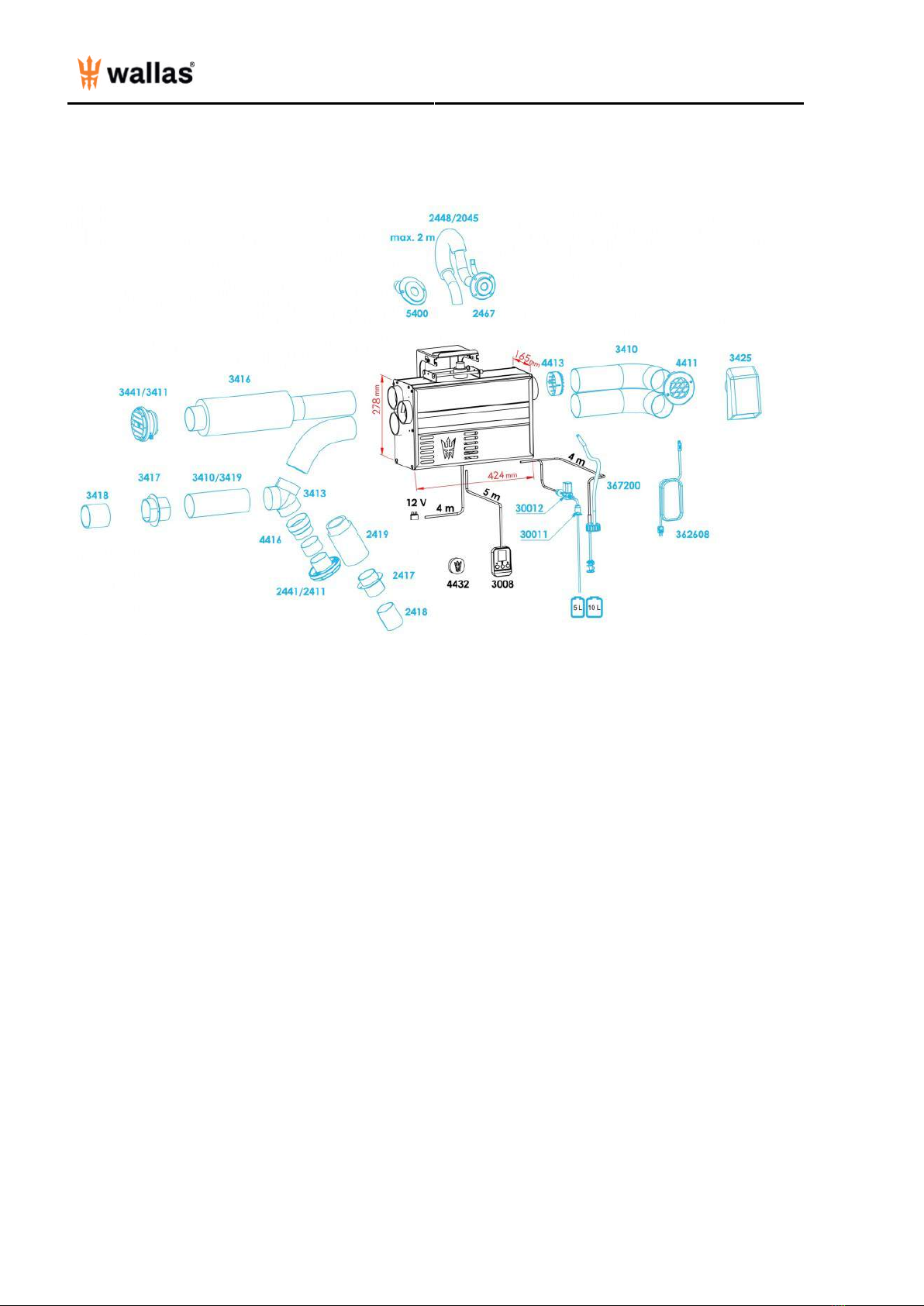
Technical information - Accessories and measures 1 ...........................................................................
Technical information - Technical information 2 .....................................................................................
Technical information - Operation description 3 .....................................................................................
Technical information - Things to note before Installation 4 ............................................................
Installation - Fastening the device 5 ............................................................................................................
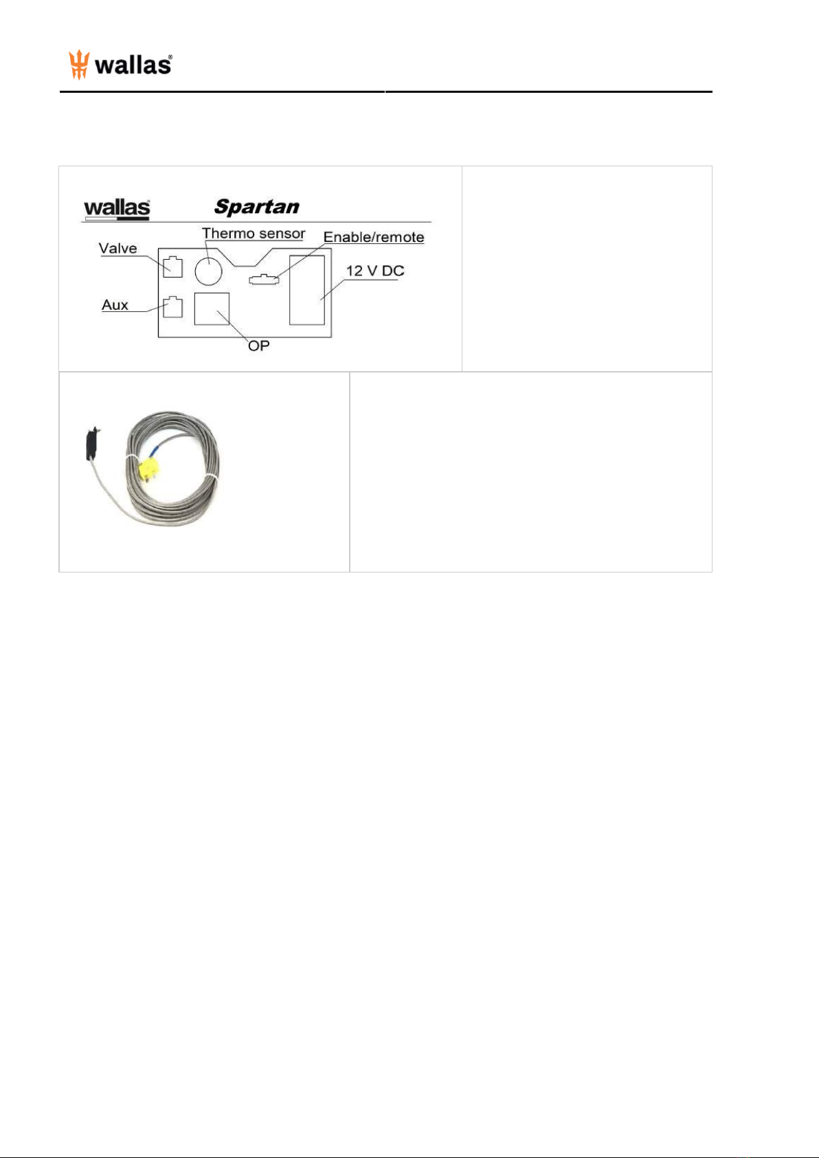
Installation - Electrical connections 7 ..........................................................................................................
Installation - Electrical connections B 8 ......................................................................................................
Installation - Warm air ducting 10 .................................................................................................................
Exhaust gas connections - Exhaust gas connections coaxial 11 ......................................................
Exhaust gas connections - Side lead-through 2467 13 .........................................................................
Exhaust gas connections - Stern lead-through 5400 14 ......................................................................
Exhaust gas connections - Insulation kit 14 ..............................................................................................
Exhaust gas connections - Drainage lock 2471 15 ..................................................................................
Fuel connections - Fuel connections 16 .......................................................................................................
Fuel connections - Fixed tank connection 30011 17 ..............................................................................
Fuel connections - Separate tank connection 18 ....................................................................................
Fuel connections - Solenoid valve 19 ...........................................................................................................
Fuel connections - Tank external filters 20 ................................................................................................
Fuel connections - Selecting the fuel 21 .....................................................................................................
Operation - Device operation 22 .....................................................................................................................
Control Panel - Control Panel 3008 basic features 24 ...........................................................................
Control Panel - Software update 32 ..............................................................................................................
Control Panel - Wallas Remote application and Control Panel connection 33 ...........................
Control Panel - Error Codes 39 .........................................................................................................................
Important information - Installation check list 41 ..................................................................................
Important information - Maintenance recommendations 43 .............................................................
Important information - Warranty terms 44 ..............................................................................................
Important information - Disclaimers 46 .......................................................................................................
Back cover - Wallas - Spartan Air 47 .............................................................................................................

- 1 -
Accessories and measures
Standard delivery includes Diesel heater, Fuel hose (4m), Power cable (4m), mounting plate, control panel (3008),
wired thermo sensor (362608) and wireless temperature beacon (4432).
2410 Warm air duct, 60 mm
2411 Warm air ventilation ø 60 mm
2417 Bulkhead lead through 60 mm
2419 Insulated warm air duct d 60 mm
2441 Warm air ventilation ø 60 mm, white
2448 Coaxial / Duplex exhaust hose 28 / 45 mm
2467 Coaxial / Duplex hull exhaust lead-through 28 / 45 mm
3008 Advanced control panel for XP400
3410 Warm air duct ø 75 mm
3411 Warm air ventilation grill ø 75 mm
3413 Warm air 3-way divider 75 mm
3416 Silencer 75 mm
3417 Bulkhead lead through 75 mm
3418 Duct extension 75 mm
3419 Insulated warm air duct 75 mm
3425 Water protected inlet grill 75mm
3441 Warm air ventilation grill ø 75 mm, white
30011 Tank fitting / diesel
30012 Magnetic solenoid valve 12V/0,5 A
362608 Wired thermo sensor
367200 Lead through kit for separate tank
4411 Intake grill 75mm
4413 Inlet grill 75mm
4414 Duct adapter ø 60/75 mm
4432 Wireless temperature beacon
5400 Stern exhaust lead-through, 28 / 45 mm

- 2 -
Technical information
Fuel Diesel oil, light furnace oil, HVO-fuel (Renewable fossil free fuel)
HVO EN 15940, B10 EN 16734, D20/30 EN 16709
Operating voltage 12 V DC
Fuel consumption 0,16 l/h - 0,46 l/h (5,4 - 15,5 oz/h)
Heating power 1,4 kW - 4,5 kW (4,700 - 15,300 BTU)
Air flow min (50 mbar counter pressure) 102 m³/h (60 cfm)
Air flow max (50 mbar counter pressure) 226 m³/h (133 cfm)
Power consumption 0,7A - 4,5A (9A during start up, 4 to 8 min)
Dimensions (L x H x W) 165 x 424 x 309 mm (16 11/16" x 12 1/16" x 6 1/2")
Weight 15 kg (33 lbs)
Maximum permitted length of exhaust pipe 2 m coaxial (2448)
Maximum permitted length of fuel hose 8 m
Maximum permitted length of outlet air duct 8 m for upper and middle ones,
5 m for lower outlet
Maximum permitted length of inlet air duct 2 m for each
Minimum area of the replacement air opening 225 cm²
Warm air connection 3x75 mm Spartan Air
2x75 mm Spartan Twin
Fresh air connection 3x75 mm Spartan Air
2x75 mm Spartan Twin
Connections Solenoid valve
Remote control
Suitable Exhaust gas lead-throughs Recommended: 2467
5400
Recommended usage temperature
-15 – +30 Celcius
Mandatory: Check your local fuel tolerance for freezing
temperatures.
Due to physical laws of thermodynamics, Wallas-Marin announces measured values with 10 % tolerance.
The values are defined in Wallas-reference measurement point with maximum ducting lengths. All tubes include four
90° bends.

- 3 -
Operation description
This is a forced air diesel heater without an exposed flame. The heater takes combustion air from outside the boat
through the outer coaxial pipe and forces exhaust out through the inner coaxial pipe. The coaxial pipe connects to a
common through hull fitting that allows both inlet air and exhaust to pass separately. This process improves
efficiency,wind resistance and lowers the minimum power level, while cooling the exhaust system.
Fresh makeup air is taken from desired areas with air intake ducting, e.g. from outside of the boat, inside the cabin
orblended. This enables good air circulation and/or cabin air replacement. Diesel engine compartment installations are
supported by the separate makeup air intake ducts, quarantining the makeup air away from any smells or noxious
engine fumes. The heating power can be adjusted freely between high and low output settings by manual control or by
thermostat. In hot and/or humid conditions, these heating units can be used for simple fresh air ventilation and
circulation.
When starting the device, the glow plug ignites the pumped fuel in the burner bowl. The glow/start and shut
downsequences are factory programmed, so - starts and stops are automatically controlled. The fuel pump inside the
heater case regulates the fuel feed and the system electronics control the fuel and air mixture to maintain an ideal clean
burning process. The temperature sensor inside the burner feels the ignition and lights up the control panel flame
indicator to indicate a successful start. When stopping the device, an automatic after cooling process takes place. This
process cleans the burner, purging any unburned fuel.
Wallas heaters are built out of the finest corrosion resistant materials to withstand marine conditions.

- 4 -
Things to note before Installation
Heater installation
Country specific regulations shall be followed in any installation. The warranty of products is valid only in installations
that are done according to this manual. Wallas recommends that the device be installed by an authorized Wallas
service shop or professional installer.
Selecting the installation location
The device shall be installed into a dry space in a protected location. The device must be mounted to a solid surface.
When installing, please note that the device needs to be removable for servicing. Connections and location should be
made so that the device can be easily disconnected for removal. For maintenance, it is recommend (not mandatory) to
leave 200 mm (7 7/8") empty space below the heater for the removal of the bottom cover of the heater.
The heater should be installed vertically level when the boat is on an even keel. The static inclination must not exceed
5°. While the device will tolerate being temporarily tilted to a steep angle (even for some hours), the burner will not yield
optimal performance if it is constantly inclined.
Select the place of installation to allow a minimum amount of bending in the warm air ducting. Avoid installing the
heater and control panel in the immediate vicinity of any potential water intrusion. If possible, install the control panel on
a vertical surface.
Installation of pipes, hoses and cables
Power cables, warm air and fuel hoses must be protected in locations where they are susceptible to mechanical
damage due to sharp edges or heat. All cables and hoses should have a fluid precluding "drip loop" to prevent water or
other fluids from following wires or hoses to the heater.
Installation space
The device can be installed within the heated space or outside of it. If located in an unheated area, heating
performance can be improved by installing the an intake air tube to the heated space (warm return air). If located inside
the heated area, air refreshing performance can be improved by installing the an intake air tube to the outside air (cold,
dry fresh air to be heated). A blend of return air and fresh air for makeup air is usually optimal.
It's forbidden to install the heater to a space which may contain gasoline fumes!
Following sections of manual are presenting important basic installation information but if you have any questions
please be free to contact purchasing/local distibutor point for more information.

- 5 -
Fastening the device
There are two different ways to install the heater; wall mounting installation and floor mounting installation.
Wall mounting (most common and recommended)
Fix the mounting plate with screws to a suitable place
and check that the bottom of the heater is in horizontal
position. The heater weights 15 kilograms (33,07 lbs)
and it must be well fastened to withstand heeling of
vessel in all directions.
Ensure that the wall is stable enough for the heater.
Lift the heater into the mounting plate.
And lock the device with the mounting bolts.

- 6 -
Floor mounting
The heater can be installed to the floor by using "legs". Secure the device to a flat stable surface which is not tilted
more than 5 degrees from the horizontal plane. The "legs" and necessary screws can be found from the accessory bag.
The heater weights 15 kilograms (33,07 lbs) and it must be well fastened to withstand heeling of vessel in all directions.
Measures:

- 7 -
Electrical connections
Safety instructions for wiring the heater:
Make sure that electrical cables are not damaged. Avoid: chafing, kinking, jamming or exposure to heat.
Electrical connections and ground connections must be free of corrosion and firmly connected.
Things to note about the connections
All connections must be arranged in the craft so that they can function perfectly under normal operating conditions.
Insulate unused cable ends.
The device uses 12 V (nominal) direct current voltage. To minimize current losses, make the power cable as short as
possible and avoid joining. The cross-sectional area of the cable is dependent on the length of the power cords. The
cross-sectional area of the cable must be consistent all the way from the stove to the battery. The maximum length of
the power cord is 10 m, based on 6 AWG cable.
The cross-sectional area of the cable
Total length of the power
cord (m)
Minimum cross-sectional area of the cable in square mm (US
Gauge)
0-4 4 (12 or 11 AWG)
4-6 6 (9 or 8 AWG)
6-10 10 (7 or 6 AWG)
If a thicker cable is required, make a separate joint in the power cord. See picture "Electrical connections of the device".

- 8 -
Electrical connections B
Electrical connections from power system:
12 V direct current system
Connect the red wire of the power cord to the plus terminal of the battery and the black or blue wire to the minus
terminal. A 15 A main fuse must be installed near the battery on the red plus wire of the power cord. See picture
above.
24 V direct current system
If the device is to receive power from a 24 V system, always connect a charging voltage reducer and a 12 V battery
before connecting the device.
Without the battery most voltage voltage reducers will not be enough on its own as it cannot generate the large amount
of current the glow plug requires.
After the 12 V battery, the connection is the same as in a 12 V system. Note, if using remote wire, the remote wire also
needs 12V, not 24V.
For DC DC 24/12 converter ask recommendation from your local dealer. There are major differencies between them.
Checking the connection
The device consumes most power when it is started up (glowing). At this point voltage losses are also at their highest.
During the glowing phase, the voltage must be at least 10 V measured at the quick coupling. See picture. If the voltage
is lower than this, the device may not start.
All wires needs to be mounted with smooth bending and equipped with strain relief.

- 9 -
Connection points of the device:
OP (not in use)
12 V DC Power cable
Thermo sensor Wired Thermo sensor
Valve Magnetic solenoid valve cable (accessory)
Enable/remote (not in use)
Aux (not in use)
Wireless or wired thermostat needs to be connected if the
heater is used in thermostat mode.
As a primary room temperature sensor Wireless thermostat is
recommended, because it is the most accurate thermostat.
It is recommended to connect the Wired thermostat also
(even it's not perfectly located in the cabin) as an important
back up for the Wireless thermostat. If the battery of the
Wireless thermostat is low the system will automatically start
to use the wired sensor.
If the heater does not have any sensors connected and the
room temperature monitoring is not available, heater goes to
safe mode and runs only in the minimum power.
Accessory installation:
For installations see page Solenoid Valve (Wallas code 30012)

- 10 -
Warm air ducting
Warm air ducting of the heater
It is important to plan the proper routing of the duct and the locations of the air vents. It is good to locate the heater as
near as possible to the area being heated. Avoid the use of sharp bends in the ducting and keep overall bends to a
minimum.
Outlet ducting
Heated air is distributed through the boat with 3410 ø 75mm duct. Multiple outlets can be installed by adding 3413 ø
75mm “Y” fittings leading to various locations. All duct to “Y” and duct to vent connections should be clamped.
The 3411 air vents are adjustable for direction and flow and located at each duct termination point. It is important that
sufficient flow is allowed by the installed vents to maintain (limit) the heater temperature. To ensure this for some
applications, the adjustment flap of the vent in the bigger heated space, will be removed. Too much resistance in the
ducting (too many flaps closed) and the heater may overheat and shut down.
If the heater will be used mainly with thermostat control, the control panel should be located in the largest heated area.
To minimize the loss of heat energy, any longruns and/or runs in areas that do not require heating can be insulated
using 3412 insulation. Insulation nearer the heater will be more effective than insulation at the far ends of duct runs.
Inlet ducting and makeup air
The heater can take air for heating (makeup air) from either the heated area (return air) or from outside the boat (fresh
air). In most cases, a mixture of both is the best choice. The upper of the intake air ducts should be installed to take
fresh air from outside and the lower return air from inside of the boat. Intake air grilles 4411 should be installed into the
head of the inlet ducts to preclude foreign objects from entering the heater. Protect the outside grill from splash water,
spray etc. If the makeup air will be taken from the same space where the heater is installed, there is no need for the
inlet air ducts, but 4413 protective grills should be present. There has to be minimum 200 cm2 (32 square inches)
ventilation/cooling air opening in the space where the heater is installed.
Make sure that intake hoses are installed so that there is no possibility to suck exhaust- or other fumes to the heater, it
may lead carbon monoxide poisoning which has severe concequences to health or may lead to death.
Silencers
There are available silencers 3416 (75mm) and 4421 (90mm) for the air hoses. Especially if the inlet hose is taking air
from inside from the sleeping space, and/or warm air outlet is blowing the air to the sleeping space the silencer is
recommended to use to maximize comfort.
Silencers reduce the sound level 50-75%.

- 11 -
Exhaust gas connections coaxial
Exhaust gas lead-throughs
It is important to choose right part for right purpose. Coaxial exhaust gas lead-throughs 2467 and 5400 are
recommended for Wallas unit. The ø 28/45 mm lead-throughs fit the exhaust gas hose 2448, providing maximum wind
tolerance.
All exhaust gas lead-throughs are stainless steel.
General instructions for exhaust gas connections
Location
Air must always flow freely past the lead-through. Install the lead-through on a flat surface. Avoid corners or recessions
where wind pressure can disturb the functioning of the device.
The minimum distance of the lead-through from the fuel tanks filler hole is 400 mm (16").
The minimum distance of the side lead-through from the surface of the water is 500 mm (20"). Especially in sailboats it
should be noted that the lead-through must never be submerged for more than 5 seconds.
It is recommended to place the lead-through in the side as far back as possible or directly in the transom.

- 12 -
Installation
When preparing the installation cut-out for the lead-through, it is a good idea to use the lead-through as a model for the
cut-out. Seal the installation cut-out with silicone in addition to the lead-through seal. Note! Do not use silicone on a
wooden boat. The side lead-through must always be equipped with a "goose neck" section. The goose neck will
effectively prevent splash water from getting to the device. The highest point of the goose neck must always be above
the surface of the water. The device will go out, if the exhaust gas lead through is submerged for more than 5 seconds.
Other things to note
Exhaust gas is hot. Always ensure that there is nothing that is susceptible to heat damage within 200 mm (8") of the
effective area of the exhaust gases (e.g. ropes, fenders or the side of another boat). All lead-through's raise the
temperature of their surroundings. A wooden deck, in particular, may dry due to the heat. Remember that the surface of
the lead-through is hot during use.

- 13 -
Side lead-through 2467
A side lead-through is installed in the side of the boat or in the transom. In sailboats it is recommended to install it in the
transom. The installation always requires a so-called goose neck. Make the necessary installation cut-outs and spread
a suitable sealing agent on both sides of the seal and on the screw holes. This will ensure that the connection is
waterproof.
The 1028 exhaust gas pipe must be 30-50 mm (1 3/16" - 1 31/32") longer than the 2045 inlet pipe. This way the
exhaust gas pipe will stay in place in the lead-through more firmly. The measurement depends on the overall length of
the piping.
2467 package contents
1 pcs Side lead-through
1 pcs Accessory bag 17679
4 pcs Fastening screw M5 x 40 mm
4 pcs Nut M5
4 pcs Washer 5,3 x 10 mm
1 pcs Hose clamp 32 - 50 mm
1 pcs Gasket

- 14 -
Stern lead-through 5400
Exhaust lead through for negative transom. Designed especially for sail boat´s stern.
Follow instruction from coaxial lead trought.
Insulation kit
An insulation kit (2461) must be used to insulate the lead-through from the boats metal hull. The insulation kit insulates
the exhaust gas lead-through and the device from each other. In fault situations the insulation kit prevents electric
circuit running between the metal hull and the device. This could result the oxidation or malfunctioning of the devices
circuit board and the circuit board would be damaged.

- 15 -
Drainage lock 2471
It is recommended that a drainage lock is installed if there is a risk of condensed or splash water entering the exhaust.
If necessary, a drainage lock can be installed into the exhaust pipe of a hull lead-through, but note the drainage lock
must be positioned after the gooseneck.

- 16 -
Fuel connections
The standard length of the fuel hose is 4 m (max 8 m). Cut the fuel hose to a length suitable for installation.
The lift height of the pump should be less than 2 m; preferably 0.5-1 m. The fuel pipe must always have a Wallas filter.
The fuel filter can be installed either near the device, near the tank, or in another location where it can be easily
checked and replaced, when necessary.
Diesel engine fuel filters and/or separators are not approved for use. All soft connections should be made with rubber or
silicone hose which is resistant to fuel. When joining with rubber connectors, tubing ends should butt against each
other.
Fuel lines other than those supplied by Wallas should be small bore (2-3mm) and must be qualified for suction use.
Typical rubber fuel hose is not qualified for suction use, having a soft, collapsing inner wall lining. Please contact your
Wallas dealer/distributor if non-standard fuel lines are being considered.
Connection to a heater
Use pliers to hold the pump inlet elbow steady, while you tighten the 12 mm fuel line nut. The joint has to be very tight
to prevent air leaks.
Tightening torque is 19Nm(14ft/lbs).
Country-specific requirements
The standard fuel hose is plastic. Please observe country-specific requirements with regard to the material of the fuel
hose/pipe and the fuel filter. The inner diameter of a new replacement hose should be equal to the inner diameter of the
plastic hose. Copper pipe 300692 and metal filters 30016 are available as accessories. Ask local requirements from
your distributor.
Fuel feed
If the lift height exceeds 2 m, the fuel feed must be checked and, if necessary, adjusted.
The fuel feed must also always be checked, if parts of the fuel system, such as the pump or the electronics card, have
been replaced. Fuel system adjustments are device specific. These adjustments should only be carried out by an
authorized service shop.
Connection to a fixed tank supplying other diesel consumers
The Wallas device must have a dedicated (not shared) connection with a fuel filter outside the tank.
Connection to a separate tank
Cap run-throughs and sintered filters are used on plastic tanks. The fuel tank should be mounted securely.

- 17 -
Fixed tank connection 30011
Installation instructions for Tank connection 30011
You will need to make a Ø 25 mm (1") hole in the upper surface of the fuel tank. Choose the location of the hole
so that when the fuel tank tilts the end of the intake pipe will stay in the fuel even if the tank is not full. If the end
of the intake pipe does not reach the fuel, the device will quickly choke on the air in the fuel system and that can
cause malfunction to the system.
Cut the fuel intake pipe (Ø 3.2/0.8 mm) to the appropriate length. The end of the pipe must not touch the bottom
of the tank in order to keep water and sediment from the system. It is recommended to cut the pipe short
enough to leave the engine intake pipe at a lower level. This way the device cannot empty the tank.
Install the pipe straight end first and angle the two "ears" at the bottom of the threaded barrel inside the hole and
then align the threaded barrel vertically so the ears are hooked on the underside of the tank top. Carefully slip
the rubber washer over the bent pipe end and over the threaded barrel, followed by the metal washer and the
nut. Thread the nut to the threaded barrel and tighten, sealing the fitting to the top surface of the tank.

- 18 -
Separate tank connection
Installation instructions for separate tank connection
If the fuel will be taken from a separate Wallas day tank, you must install a tank connection 367200 (4 m).
Tighten the barrel nut tightly to the fuel pump connector at the device end of the fuel system. Keep the parts and
the hose clean and ensure that the connection is tight, because an air leak in the connector will stop the device
from functioning.
Install the tank connection in the tank.
The joint has to be very tight to prevent air leaks. Tightening torque is 19Nm.
Wallas fuel tanks
Volume Length x height x width WALLAS code
5 l 200 x 300 x 130 mm 2024 (accessory)
10 l 380 x 195 x 210 mm 2027 (accessory)
33 l 500 x 230 x 350 mm 4030 (accessory)
130 l 800 x 400 x 600 mm 4130 (accessory)

- 19 -
Solenoid valve
The solenoid valve 30012 (available as accessory) prevents the tank from emptying in case the fuel system fails. The
fuel filter should be installed before the solenoid valve.
Our recommendations in the following installation scenarios:
1. Fuel level is below the
heater/stove. Picture 1.
• Recommended installation scenario
• No special accessories required
2. Fuel level may temporarily rise
above the heater/stove (e.g. in the
fuel tank filler pipe or when the boat
tilts). Picture 2.
• No special accessories required but
solenoid valve 30012 is
recommended.
3. Fuel level is above the
heater/stove. Picture 3.
• Non-recommended installation
scenario
• Possible siphon problem
• Solenoid valve 30012 must be
installed in the fuel hose near the
tank.
Other manuals for Spartan
3
This manual suits for next models
1
Table of contents
Other wallas Heater manuals
Popular Heater manuals by other brands

THERMOBILE
THERMOBILE IMAC 4000 GAS US user manual

ORIGO
ORIGO CH-C24 instruction manual

L.B. White
L.B. White Oval 80 v.2 Owner's manual and instructions

DR. Heater
DR. Heater DR-968 owner's manual

Scarlett
Scarlett SC-1166 instruction manual

Technotherm
Technotherm KBS 6/25 Assembly and operating instructions

BLAUBERG Ventilatoren
BLAUBERG Ventilatoren EKH Series Operation manual

Stadler Form
Stadler Form Anna operating instructions

Frico
Frico Thermoplus EC450 Mounting and operating instructions

impress
impress MI-701 Use and care guide

Versonel
Versonel SPP1500SBH owner's manual

Klarstein
Klarstein 10031808 manual