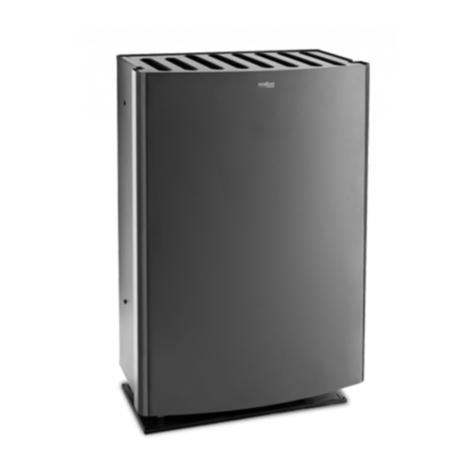
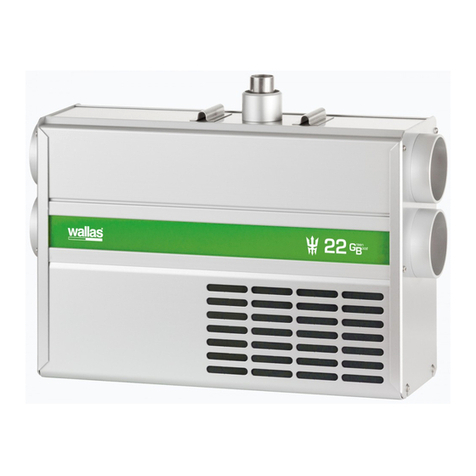
wallas 26CC Manual

Technical information en
Supplies and accessories
Standard delivery Installation accessory Special installation Accessory
Fuel tank socket case
Remote control system
Exhaust head
Timer/week program, mechanical
Timer cable
Mounting kit
Solenoid valve
Fuel tank, 30 l
Fuel tank, 10 l
Combustion air pipe Ø 45 mm, Al
Exhaust pipe Ø 50/45 mm, stainless
Protection tube 0,5 m, fuel hose
Control panel cable, 6 m
Extension line, 2 m
Fuel tank, 130 l
Insulating channel
Insulation mantel plate Ø 115 mm / 0,3 m
26CC / 40CC
D80151
- 37 -
4031
4206
363055
4430
4004
4880
30017
4030
2027
4045
4845
4033
363054
26CC / 40 CC
4032
4130
4012
4015
4845
4045
4033
4212
4206
4004
4031
4032
30017
4880
604398.ai 1 3.11.2011 13:38:19
4430
490525C

Technical information
Device package contents
Alternative front panels and their content
Front panel, grey 26CC
Fastening screw M4x16
1 pcs
4 pcs
Front panel, pine pattern 26CC
Fastening screw M4x16
1 pcs
4 pcs
Front panel, grey 40CC
Fastening screw M4x16
1 pcs
4 pcs
Front panel, pine pattern 40CC
Fastening screw M4x16
1 pcs
4 pcs
Front panel, grey Front panel, pine pattern
Installation, operation and maintenance instructions
Fuel tank connection
Short circuit connector for mountain switch
1 pcs
1 pcs
1 pcs Accessory bag 260941A
1 pcs
Heater without front panel
Control panel package 361061A
Fuel hose, 4 m
Control panel rim for surface mounting
Power cable with connector and integrated fuse 15 A (4m)
1 pcs
1 pcs
1 pcs
1 pcs
Control panel fastening screws 3,5x40
Pipe clamp 48 mm
Hose binder 32-50 mm1 pcs
1 pcs
1 pcs
4 pcs
4 pcs
Control panel cable, 3 m1 pcs
Fastening screws 5x30 (black)
Installation:
See page 55.
en
Control panel1 pcs
26CC / 40CC
D80151
- 38 -
26GF
26PF
40GF
40PF
26CC / 40CC
11
10
12
490525C

Technical information
Heater operation
Wallas heaters 26CC and 40CC have been designed especially for use in holiday
cottages.
Lightfurnaceoil,dieseloilorparafncanbeusedtofuelthedevice.Theheateris
fed with fuel from a separate tank, which is positioned below the heater. The heater
is powered by a 12-volt battery, which can be recharged, for example, by a solar
cell, wind generator or a mains power adapter.
The combustion air is fed in from outside the device and its circulation is complete-
lyenclosed,andbalancedwiththeue-gasexhausthead,whicheliminatesthe
effect of wind pressure on the combustion.
The heater’s evaporation burner is activated automatically when the device is
started. The glow plug in the burner ignites the fuel that has been pumped into the
burner.Theglowtimeisxed:itstartsandendsautomatically.
Theheatsensor,intheheater,detectstheame’sheatandlightstheredLEDto
signal that the device has started.
All functions are controlled electronically. The fuel pump and combustion air blower
arefullystabilisedagainstvoltageuctuations,whichensurescleancombustion,
regardless of changes in the battery voltage.
Theheaterisequippedwithbuilt-inoverheatprotection,whichcutsthefuelfeedif
the device overheats.
When the heater is switched off, it cools down automatically. The cooling function
ventilatestheburner,anddischargestheue-gasesgeneratedduringtheswitch-
off, to the outside of the cottage.
Fuel
Operating voltage
Consumption
Heating power
Power consumption
Measurements
Weight
Max. permissible length of the ue
gas pipe
Max. permissible length of the fuel
hose
Heating area
Suitable ue gas lead-throughs
Accessories
Connections
Power adjustment
Start-up
Light furnace oil / diesel oil (cold resistance grade according
toconditionsofuse)orparafn
0,2...0,4 A (when ignited ca. 4,5 min. 8 A)
3 m, (6 m insulated)
4031 Base housing
4206 Weekly timer
4430 Remote controller
Remote controller
Room thermostat or manual power control
Manually with a switch or with the automatic weekly timer
(accessory) or remote controller (accessory)
ca. 18,5 kg ca. 25,0 kg
ca. 40...60 m2 ca. 60...90 m2
en
26CC / 40CC
D80151
- 39 -
12 V DC
0,09...0,26 l/h
900...2600 W
730x340x200 mm
6 m
4004
26CC 40CC
730x440x240 mm
1600...4000 W
0,16...0,4 l/h
490525C

Technical information
Operating principles
en
26CC / 40CC
D80151
- 40 -
P
12 V
490525C

Installation
Things to note during installation
Basic installation methods
The most common installation method is a wall lead-through. Installation kit 4880
andaue-gasexhausthead4004 have been used in the installation. In addition,
the fuel tank 4030 (30 l) has been installed in the base housing 4031.
Flueinstallation.Thisinstallationmethodrequiresthebuilding’schimneytohave
oneueavailable.Theuemustnotbeconnectedtootherreplacesorequip-
ment. Installation kit 4880isrequiredfortheinstallation.Intheexampleinthe
picture, the fuel is fed from the fuel tank 4130(130l)undertheoor.
Things to note when selecting the installation location
When selecting the installation location and method, note the following:
• If you choose the wall lead-though method, install the device on a wall where
thewindpressuredoesnotdirectlyimpingetheue-gasexhausthead.When
the device is running on low power, wind pressure can snuff out the burner
ame.Theburnerwillalsogeneratemorescaleduetochangesinwindpres-
sure.
• The length of the control panel wire is 3 m. Do not install the device near to an
external door or a window, because the temperature changes in these loca-
tions are too great. The control panel contains a thermostat sensor.
• Flue installation will slightly increase the generation of burner scale.
• Avoid making the fuel and electrical lines that lead to the device excessively
long.
• The device must be positioned so that it is protected from water drips, spills or
splashes.
When installing the device, bear in mind that may be necessary to detach the
device for maintenance. Therefore, it is advisable to make the connections easy
to open and disconnect. The device does not need to be detached to clean the
burner.
The heater should be installed on the level. The inclination must not exceed 5°.
While the device should not breakdown, if it is temporarily tilted at a steep angle
(even for some hours), the burner will not yield the optimal performance, if it is
continuously inclined.
Also, consider where you place the control panel, as the length of the control
panel’s cable may pose some limitations.
Avoid installing the control panel in the immediate vicinity of a water outlet.
If possible, install the control panel on a vertical surface.
We recommend that the device be installed by an authorised Wallas service shop.
Wall lead-through
Flue installation
en
26CC / 40CC
D80151
- 41 -
490525C

Installation
Protection of pipes, hoses and cables
Power cables and fuel hoses must be protected in locations where they are sus-
ceptible to mechanical damage due to sharp edges or heat.
Safety distances
Distance from surrounding walls. Observecountry-specicrequirements.
There must be enough clear-
ance between the wall and
the device so that the space
can be kept clean and free of
dust, litter and other unwanted
objects. The openings for the
air intake, in the lower section
of the device’s casing, must be
unobstructed.
There must be no surfaces,
structures or objects that are
ammableorcanobstructthe
heat, within 1 m above the
device’s upper surface.
Safety distances
Device over 1300 m above sea level
If the device is installed over 1300 m above sea level, a short circuit connector to
activate the mountain switch has to be added into a connector J14 of the device’s
circuit board. The connector is in the accessory bag.
Do not remove the jumper (or change its location) from the device’s circuit board.
Always use original Wallas accessories and parts with Wallas equip-
ment.
en
Short circuit connector
for mountain switch
26CC / 40CC
D80151
- 42 -
min 70 mm
min 100 mm (SE)(NO)
min 50 mm
min 1000 mm
490525C

Installation
Flue gas connections
Exhaust head 4004
Covering plate 360x360
Fastening screw 4,5x15
1 pcs
2 pcs
8 pcs
Fastening screw 4,5x254 pcs
Accessory package contents
2 pcs
1 pcs
Instructions for wall lead-through installation
Accessories 4004 and 4880arerequiredfortheinstallation.
Note that different measurements for insulation are given for Finland, as opposed
to Sweden and Norway, due to different national regulations.
10. Drill or cut an opening in the wall for
• the exhaust pipe and its insulation (ø 120 mm, Finland – ø 320 mm, Sweden
and Norway). Note the different measurements for models 26CC and 40CC.
• the combustion air intake pipe (ø 50 mm). The cover plate (16) can be used
as a stencil.
11. Cut both pipes (18 and 21), so that the pipes extend from the wall ca. 40 - 45
mm (23 and 24) when the pipes have been pushed all the way in the heater
connection pipes (25 and 26) and the heater is positioned at least 70 mm (Fin-
land) / 100 mm (Sweden and Norway) from the wall.
12. Install the cover plates (16 ja 17) on the lead-through openings and seal the
connection between the wall and the plate with silicone paste.
13. Push the pipes (18 and 21) all the way into the connection pipes (25 and 26)
and seal the exhaust pipe’s connection (25) with a pipe clamp (11) and the
combustion air pipe’s connection (26) with a hose binder (10). (Both ties can be
found in the heater accessory bag.) The exhaust pipe cannot be tightened suf-
cientlybyanyotherfasteningthanapipeclamp(11),whichmustbetightened
sufcientlytolockthepipeinplace.
14. Place mineral wool (19) on the exhaust pipe (18) so that the insulating material
extends from the back surface of the heater to ca. 10 mm outside the wall (27).
Place the insulation mantel plate (20) on the insulation.
15. Then, push the heater to a distance of 70 / 100 mm from the wall, while guiding
the hoses and the insulation through the lead-through openings.
16. Adjust the length of the insulation mantel plate (20), by cutting it so that its end
Exhaust head 4004
Mounting kit 4880
en
Exhaust head 4004
Insulating channel 4012
Insulation mantel plate, 0,3 m 4015
Exhaust pipe 4845
Combustion air pipe 4045
Mounting kit 4880
Comb. air intake shield 4051
26CC / 40CC
D80151
- 43 -
15
16
15
17
17
16
19
20
18
21
22
0,5 m
0,5 m
19
21
18
1 m
20
22
30
34
date author inspectedand approved code
ratio version
drawingno.
name
material
Arkki A3
finishing mass
Description
Rev author& date Productmust fulfil the RoHS-directive
(Directive2002/95/EY)requirements.
General tolerance ISO 2768-m
date author inspected and approved code
ratio version
drawing no.
name
material
Arkki A3
finishing mass
Description
Rev author & date Product must fulfil the RoHS-directive
(Directive2002/95/EY)requirements.
General tolerance ISO 2768-m
490525C

Installation
protrudes from the wall ca. 10 mm, and cut the edge of the sheet metal into
10–20 mm strips (28), as shown in picture 1. Fold the strips carefully on to the
surface of the sheet metal cover.
17. Sealtheclearancebetweenthesheetmetalcover(17)andtheue-gasex-
haust head (15) with silicone paste and push the head into place in the wall.
Attachtheheadtothewallwithscrews(30,4items4,5x25).Thelidoftheue-
gas exhaust head (15) must be opened before installation - screw (31). Ensure
that the ends of the hoses (23 and 24) extend to the limiters (32 and 33).
18. Finally,fastentheheatertotheoororthebasehousing(12).
Installation measurements
Additional insulationInstallation measurements
Measurements in Finland Measurements in Sweden and Norway
Note the different measurements in Finland compared to Sweden and
Norway.
ø 320 mm insulation
en
26CC / 40CC
D80151
- 44 -
28
30
ø 50 mm
ø 120 mm
100 mm
255 mm
275 mm26CC
40CC
155 mm
175 mm26CC
40CC
100 mm
28
30
34 34
490525C

Installation
Picture 1.
Installation in Finland
Installation in Sweden and Norway
ø 320 mm insulation
en
26CC / 40CC
D80151
- 45 -
26
25 23
16 17
15
32
33
29
24
21
18
20 31
10
12
11
28
70 mm
100 mm (sv)(no)
19 27
490525C

Installation
Instructions for attachment to the ue
Accessory 4880isrequiredfortheinstallation.
1. Cuttheue-gaspipe,theinsulationchannelandthecoversheetmetaltoa
lengthatwhichtheyextendtotheinnersurfaceoftheue.
2. Fastenthehosestotheheaterwithclamps.Theue-gaspipemustbetight-
enedrmlywithapipeclamp.
3. Puttheheaterinplace,andfastenittotheoororthebasehousing.
4. Insulatethejointbetweentheue-gashoseanduewithacryliccompound.
5. The device is ready for use after you connect the power cord and the fuel hose.
Note!
Ifyouchoosetoleadinthecombustionairfromundertheoor,ensurethereissuf-
cientventilationinthefoundationsbeneaththeoor.Installtheprotectivespiralon
the end of the hose.
Inatall(over5m)ue,withalargecross-sectionalsurface(over15x15cm),the
temperatureoftheue-gasesdecreasesomuchthatthemoistureinthemcon-
denses,resultinginfunnelcorrosionandaweakenedairow.Duetothis,abrick
ueshouldbecasedwithastainlesssteelpipe(diameter:50–70mm)andthegap
betweenthepipeandtheuelled,forexample,withLECA.
Combustionairmustnotbetakenfromtheue.
en
26CC / 40CC
D80151
- 46 -
19
20
18
19
20
4845
21
22
490525C

Jointing
A jointing should only be made in long
power cords, if necessary, in which
case the cord must be replaced with
a thicker one. The jointing cannot be
further than 1 meter from the device.
Electrical connections
Things to note about the connections
The device uses 12 V direct current voltage. To minimise current losses, make the
power cable as short as possible and avoid jointing. The cross-sectional area of the
cable is dependent on the length of the power cord. The cross-sectional area of the
cable must be consistent all the way from the stove to the battery. The maximum
length of the power cord is 10 m.
Electrical connections of the device
12 V direct current system
Connect the red wire of the power cord to the plus terminal of the battery and the
black or blue wire to the minus terminal. A 15 A main fuse must be installed near
the battery on the red plus wire of the power cord.
Checking the connection
The device consumes most power when it is started up (glowing). At this point volt-
age losses are also at their highest. During the glowing phase, the voltage must be
atleast10.7Vmeasuredatthequickcoupling.Ifthevoltageislowerthanthis,the
device may not start.
Princible diagram of the electrics.
Installation
Total length of the power cord (m) Cross-sectional are of the cable (mm2)
Ifathickercableisrequired,makeaseparatejointinthepowercord.
Device’s quick
coupling
Main fuse
Power cord
en
The cross-sectional area of the cable
26CC / 40CC
D80151
- 47 -
0 - 4
4 - 6
6 - 10
4
6
10
490525C

Installation
Fuel connections
Things to note about the connections
The standard length of the fuel hose is 4 m (max 6 m). Cut the fuel hose to a length
suitable for installation.
The lift height of the pump should be less than 2 m; preferably 0.5–1 m.
Thefuelpipemustalwayshavealter.
Country-specic requirements
Thestandardfuelhoseisplastic.Pleaseobservethecountry-specicrequire-
mentswithregardtothematerialforthefuelhose/pipe,thefuellterandthehose
clamps.Theinnerdiameterofanewreplacementhosemustbeequaltotheinner
diameter of the plastic hose.
Copperpipeandmetalltersareavailableasaccessories.
Fuel feed
If the lift height is outside the recommended 0.5–1 m, the fuel feed must be
checked and, if necessary, adjusted. The fuel feed must also always be checked,
if parts of the fuel system, such as the pump or the electronics card, have been
replaced.
Fuelsystemadjustmentsaredevicespecic.Werecommendthattheadjustment
be carried out by an authorised service shop.
Tank placement
1. The fuel tank should always be placed below the base of the device. (The fuel
surface level must be below the device.) When the fuel level is above the base,
the solenoid valve 30017 must be installed on the tank-side end of the hose.
2. The fuel tank can be placed in the base housing 4031, or outside it, for exam-
ple, in the foundations of the house or a suitable protective box. Protect the
tank and the fuel hose from direct sunlight.
3. The fuel hose lead-through must be shielded by a metal cover pipe.
4. The standard length of the fuel hose is 4 m. It can be extended with a 2 m ex-
tension hose, which gives a total length of 6 m. Connect the hoses with bayo-
net couplings, which are twisted together.
Optimal fuel tank location
TANK
TANK
MAXIMUM
OPTIMUM
Checking /
adjustment
Checking /
adjustment
TANK
If the fuel level in the tank is above the device, a solenoid valve 30017
must be installed in the fuel line immediately after the tank lead-through.
en
26CC / 40CC
D80151
- 48 -
0,5 m
1 m
2 m
490525C

Installation
Connection to a separate tank
Caprun-throughsandsinterltersareusedonplastictanks.
Accessory
Accessory
Accessory
Accessory
Volume length x height x width Order code
Sinter bronze lter
Cap seal
Protective spiral
Screw cap
Bleeding hose
Bayonet coupling
Bayonet coupling
Cap run-throughs
The fuel connections must be tightened rmly so as to not allow air
to leak into the hose. Always check the cleanliness of the connection
surfaces before tightening.
Air will cause the device to malfunction.
en
Wallas fuel tanks
26CC / 40CC
D80151
- 49 -
5 l 2024
10 l
30 l
130 l
2027
4030
4130
200 x 300 x 130 mm
380 x 195 x 210 mm
590 x 200 x 300 mm
800 x 400 x 600 mm
490525C

Installation
Fuel
Several different types of fuel can be used in the heater.
When selecting the fuel type, take note of the temperature limits of each particular
fuel.Thelimitvaluesprovidedherearetobetreatedasguidelines.Conrmthe
actual temperature limits from the fuel supplier.
• light furnace oil / diesel, summer grade, temperature must not fall below –5 °C
• light furnace oil / diesel, winter grade, temperature must not fall below –24 °C
• light furnace oil / diesel, arctic winter grade, temperature must not fall below
–40 °C
• parafn,theoperatingtemperaturemustnotfallbelow-40°C
Ifthetemperaturedropslowerthantheminimumlevel,parafnmayforminthe
fuel.Thismayresultinthefuellterandpumpbeingclogged.Theclogwilldissolve
only if the fuel temperature rises clearly over 0 °C.
Inwinterconditions,arcticwintergradeorparafnmustbeused.
The less aromatic substances the fuel contains, the less deposits will be formed.
Normal furnace oils contain ca. 35–40 % aromatic substances. In coloured city
diesels (e.g. Tempera 3G and 5G) and green furnace oils the concentration is 20
%.Sinceparafncontains0.5%aromaticsubstances,itgeneratespracticallyno
scale when burning.
Conrm the actual temperature limits for the fuel you are using
from the fuel supplier.
en
26CC / 40CC
D80151
- 50 -
490525C

Installation
Accessories
Fuel tank socket case, 4031
The base housing enables the device to be installed directly on the fuel tank.
A 30-litre fuel tank 4030 can be installed inside the housing. The front panel of the
housing contains an opening, through which the fuel level can be easily observed.
The front panel can be lifted off, which makes it easier to refuel the tank.
Timer/week program, mechanical, 4206
The heater can also be started with a timer.
The weekly timer allows you to heat your holiday cottage, before
your arrival, even when the cottage is outside the GSM network
coverage. The weekly timer starts up and shuts down the heater at
the times you select.
Timer cable, 4205
For use with weekly timer 4206.
Solenoid valve, 30017
The solenoid valve should be installed when the surface level of the fuel is higher
than the base of the device.
A valve protects against fuel spillages due to a possible pipe breakage.
Control panel cable 6 m, 363054
For installing the control panel more than 3 metres away (standard length).
Remote controller, 4430
WiththeextrattingsyouwillgetmoreoutofyourWallasheater.Byswitchingthe
heater on from your GSM cell phone, you will have a warm cottage waiting for you
upon arrival.
en
26CC / 40CC
D80151
- 51 -
604398.ai 1 3.11.2011 13:38:19
490525C

Device use
Normal use
Temperature is controlled by the thermostat (recommended use).
The device starts when the power switch (3) is pressed in continuously for at least
2 seconds, after which the yellow current indicator light (4) lights to indicate that the
power is on.
Theredcombustionindicatorlightwillbelit,whentheburneramehasbeen
ignited and combustion has stabilised after ca. 2.5-4 min from when the heater was
turned on.
After the heater has been turned on, you can adjust the thermostat setting using
the temperature control knob (2). Turn the knob to set the temperature to your
desired setting.
When the thermostat indicator light (5) is lit, the temperature in the space to be
heatedislowerthantherequestedtemperatureandthedeviceisincreasingthe
power.Whentheindicator(5)goesout,therequestedtemperaturehasbeen
reached.
The sun-switch shuts down the device automatically, if the temperature rises above
therequestedtemperature,forexample,duetosunlight.Thetemperaturemust
rise by +3 °C above the set value for a half an hour. If the device has been shut
down by the sun-switch, an indicator light (5) blinks on the thermostat. The sun-
switch can be turned off temporarily, by turning the temperature control (2).
A device that has been shut down can be restarted manually, if necessary.
Conservation temperature: the temperature control (2) is set to minimum, and the
room is maintained at a temperature of +2–+8 °C. The sun-switch is not enabled in
this mode.
Alternative use
The power is adjusted manually.
To enable this function, turn the power adjuster (2) to positions min - max - min
- max within 10 seconds of the yellow indicator (4) lighting up, during the device
start-up.
The device signals that the function has been activated by blinking the thermostat
indicator light (5) three times.
You can check whether or not the function is in use by turning the power adjuster
(2): the thermostat indicator light should not light up at any point.
1. Combustion indicator
2. Temperature adjustment / Power
control
3. Power switch
4. Current indicator
5. Thermostat indicator
6. Thermostat sensor
Operation
Colour Blink interval Function
Yellow
Red
Red
Power on
Combustion indicator when the com-
bustion has begun normally
Aftercooling
Thermostat control
Orange
Orange Manual power control engaged
Device in remote control mode
Sun switch has shut down the device
Orange
Orange
Device in remote control mode
Orange
en
Signal lights
26CC / 40CC
D80151
- 52 -
31 2
10 s
30 s
10 s 10 s 10 s
10 s10 s10 s10 s
1
25
6
34
M40_M26.indd 1 19.06.2008 14:47:49
1. 2. 3. 4.
5. 6.
490525C

Operation
After installation or maintenance, if the fuel line is empty, the device
may not start at the rst attempt. If this is the case, the red combus-
tion indicator light will start to blink roughly 4.5 minutes after start-
up.
Press the power switch to the OFF position. The device cannot be
restarted until the cooling phase has completed.
When it has cooled, switch the device on again.
If the device does not start after two attempts, it cannot be started
again: the device will lock down (lights blink to indicate this).
Release the lock (instructions in the maintenance section)
Depending on the length of the fuel hose, the device may have to be
started up several times. Keep an eye on how the fuel travels in the
fuel hose while starting up the device.
First start-up
After the heater has been started up, the power can be adjusted step-less with
the power adjustment knob (2). Avoid turning the adjustment knob back and forth
rapidly, as this can cause the burner to become sooty.
To end manual operation, turn the device off and restart it after allowing it to cool
normally.
Shutdown
You can shut down the heater by pressing the power switch (3) in continuously for
at least 2 seconds. The yellow current indicator light (4) will go out immediately.
Theredcombustionindicatorlight(1)willcontinuetoblinkforca.veminutes,
while the device is cooling down. You cannot restart the device until the combustion
light has stopped blinking.
Remote control
The device can be controlled manually with an accessory, which can be purchased
separately.
If the device is started using the remote control, the orange indicator light (5) on the
control panel will blink at 10-second intervals. The sun-switch is not enabled in this
mode.
Do not start the device, while the battery is being recharged from a
generator unit or a battery charger (risk of overvoltage).
Cleaning and maintaining the device
To keep the device easy to use and looking good, clean it regularly. Wipe the de-
vice with a moist cloth and dry it with another cloth. Do not use abrasive cleaning
sponges or agents. Also, avoid chemically strong cleaning agents.
Regularly vacuum the back of the device. Dust easily collects at the back of the
device,andtheairowcreatedbythedevicewillspreadthedustallovertheroom.
ObservethegeneralmaintenancerecommendationsforWallasequipmentwhen
servicing the electronic and mechanical parts of the heater.
Never use the main switch to cut the power before the cooling
phase, which starts after device is turned off, is completed.
en
26CC / 40CC
D80151
- 53 -
490525C

Special recommendations
• When selecting the fuel type, take note of the temperature limits of each par-
ticular fuel.
• Onlydiesel,lightfurnaceoilorparafncanbeusedinWallasdiesel-operated
products.
Removal of water from the tank (1)
• During the period of use, add isopropyl alcohol-based (not ethyl or methyl
based) anti-freeze for petrol vehicles (carburettor spirit) to the fuel. The agent
shouldbeaddedafterthetankhasbeenemptied,andrelled,afewtimes,
and always at the beginning and end of an operating season. The anti-freezing
agent binds the water in the fuel and prevents the fuel from settling and spoil-
ing during the summer season. For the dosage, observe the recommendations
provided by the manufacturer of the agent.
Maintenance
An anti-freezing agent for diesel vehicles may increase the forming
of scale at the bottom of the burner and therefore shorten the mainte-
nance interval.
Maintenance procedure Maintenance interval Carried out by
Inspection of basic functions
(3)
Aftertherst100l,oraftertherst
season of use
Performed by the user ac-
cording to the maintenance
instructions
Cleaning the burner (2) Regularly at a suitable interval
(100–600 l)
Performed by the user ac-
cording to the maintenance
instructions
Tankandltercleaning,and
removal of water from the
tank (1)
Once every operating season
Performed by the user ac-
cording to the maintenance
instructions
Maintenance recommendations
Basic maintenance of diesel-operated devices
en
26CC / 40CC
D80151
- 54 -
490525C
Other manuals for 26CC
2
This manual suits for next models
1
Table of contents
Other wallas Heater manuals
Popular Heater manuals by other brands

Pace
Pace HS 300 Operation manual

Mandik
Mandik HELIOS Installation, Operation Instructions and Maintenance Manual

Gabarron
Gabarron Elnur INGENIUM RD4W Installation instructions and user guide

TESY
TESY HL-275W PTC Installation and operation manual

Dyna-Glo
Dyna-Glo RA18LPDG user manual

Aerus
Aerus Apollo 2000 user manual