Warn 65400 User manual

WARN INDUSTRIES PAGE1 64220 A2
INSTALLATION INSTRUCTIONS
ATV PLOW ACCESSORY
Plow Mounting Kit: Warn PN 65400
Application: 2002+ Suzuki Vinson 500
WARNING
SEVERE INJURY OR DEATH MAY RESULT IFYOU IGNOREANY OFTHE FOLLOWING:
· Read the Plow Operator Manual, the Vehicle’s Operator Manual, and all warning labels before operating or
using your ATV plow.
· Always operate ATV at a walking speed with the blade installed. Do not exceed 5 mph (8 km/h) even with the
blade up.
· Always plow cautiously, impact with a hidden or stationary object may cause the ATV to stop suddenly or go
out of control.
· Never operate the ATV on slopes greater than 10° with the plow installed.
· Never stand or ride on the plow.
· Always stay clear of moving parts and joints. Keep others away when operating or adjusting plow.
· Always inspect the plow mechanism, fasteners, cable, and adjustments before operating. Replace all worn or
damaged parts before operating.
· Always lower the plow to the down position before leaving the ATV unattended.
DRILL THROUGH ONLY THE SKIDPLATE AND NOTHING ELSE. DRILLING THROUGHANY COMPONENT ON
THEATV OTHER THAN THE SKIDPLATE CAN SEVERELY DAMAGE THE VEHICLE WHICH CAN ULTIMATELY
LEAD TO OPERATOR INJURY OR DEATH.
FAILURE TO TIGHTEN ALL NUTS AND BOLTS SECURELY ON THE PLOW MOUNT CAN RESULT IN VEHICLE
DAMAGE AND OPERATOR INJURY OR DEATH.
DRIVE SLOWLY OVER BUMPYAND ROUGH TERRAIN. DRIVINGAT SPEEDS THAT CAUSE THE PLOW TO
BOUNCE WHILE IN THE UP POSITION CAN CAUSE THE WINCH TO BACK-DRIVE CAUSING THE PLOW TO
WORK ITS WAY DOWN. THIS MAY RESULT IN THE PLOW IMPACTINGA STATIONARY OBJECT AND CAUSE
DAMAGE TO THE VEHICLE AND OPERATOR INJURY OR DEATH. DRIVE AT SPEEDS SUCH THAT THE PLOW
DOES NOT BOUNCE AND BE AWARE OF THE PLOW POSITION WHILE DRIVINGAT ALLTIMES.
THE PURPOSE OFTHE J-BOLT IS TO BREAK THE CONNECTION BETWEEN THE PLOW AND THE WINCH TO
PREVENT SERIOUS DAMAGE TO THE ATV IFTHE PLOW IS RAISED TOO HIGH. THE PLOW BLADE WILL DROP
SUDDENLY IF THE J-BOLT BREAKS, SO BE SURE THAT THERE ARE NO BYSTANDERS WHEN YOU RAISE/LOWER
THE PLOW. DO NOT RAISE THE TOP OF THE PLOW ABOVE THE HEADLIGHTS OF THE ATV AS IT IS NOT ONLY
UNNECESSARY, BUT POTENTIALLY DAMAGING TO THE VEHICLE AND PLOW. IFYOU NOTICE DEFORMATION
OFTHE J-BOLT, OR THE J-BOLT IS BROKEN, REPLACE IT WITH THE SPARE J-BOLT INCLUDED IN THE KIT.
Your safety, and the safety of others, is very important. To help you make informed decisions about safety, we have provided
installation and operating instructions and other information on labels and in this guide. This information alerts you to potential
hazards that could hurt you or others. It is not possible to warn you about all potential hazards associated with this product,
you must use your own good judgment.
CARELESS INSTALLATION AND OPERATION CAN RESULT IN SERIOUS INJURY OR EQUIPMENT DAMAGE. READ
AND UNDERSTAND ALL SAFETY PRECAUTIONS AND OPERATING INSTRUCTIONS BEFORE INSTALLING AND
OPERATING THIS PRODUCT.
This guide identifies potential hazards and has important safety messages that help you and others avoid personal injury or death.
WARNING and CAUTION are signal words that identify the level of hazard. These signal words mean:
WARNING signals a hazard that could cause serious injury or death, if you do not follow recommendations.
CAUTION signals a hazard that may cause minor to moderate injury, if you do not follow recommendations.
This guide uses NOTICE to call attention to important mechanical information, and Note: to emphasize general information
worthy of special attention

WARN INDUSTRIES PAGE2 64220 A2
I. PARTS LIST
Ref Part Number Description Qty
A1 63849 Plow Mount 1
A2 62845 J-Bolt Bracket 1
B1 25114 6mm dia-18mm long Bolt 2
C1 35391 1/4” dia J-Bolt 2
C2 1320 1/4” Flat Washer 4
C3 1321 1/4” Lock Washer 2
C4 6725 1/4” Nylock Nut 2
D1 60664 5/16” dia-1 1/8” wide U-bolt 2
D2 1324 5/16” Washer 4
D3 2002 5/16” Nylock Nut 4
E1 1827 3/8” dia-1” long Bolt 1
E2 2195 3/8” Washer 1
E3 6779 3/8” Nylock Nut 1
II. TOOLS REQUIRED
- Rachet
- 10mm Socket
- 7/16” Socket
- 1/2” Socket
- 9/16” Socket
- 9/16” Box Wrench
- Drill
- 3/8” Drill Bit
Figure 1 Kit Hardware
Figure 2 Kit Fasteners
A1
A2
B1
E3
E1
E2
C2
C1
C4
D1
D3
D2
C3
Note: A winch with a roller fairlead or Warn electric actuator is recommended for lifting this
plow. See your local dealer for part numbers.

WARN INDUSTRIES PAGE3 64220 A2
DRILL THROUGH ONLY THE SKIDPLATE AND
NOTHING ELSE. DRILLING THROUGH ANY
COMPONENT ON THE ATV OTHER THAN THE
SKIDPLATE CAN SEVERELY DAMAGE THE
VEHICLE WHICH CAN ULTIMATELY LEAD TO
OPERATOR INJURY OR DEATH.
III. INSTALLATION
1. Remove the two bolts, located just behind the front
wheels, that hold the skidplate to the chassis as shown
in Figure 3.
2. Place the Plow Mount (A1) under the vehicle
aligning the rear tabs to the holes of the bolts that were
removed in Step 1.
3. Attach a 6mm dia-18mm long bolt (B1), 1/4” flat
washer (C2), and 1/4” lock washer (C3) through the
rear tabs in the Plow Mount (A1) and into the vehicle
chassis as shown in Figure 4. Do not tighten the
fasteners just yet, you will do this later in the installa-
tion.
4. With the Plow Mount (A1) flush against the
skidplate, drill four holes in the plow mount and up
through the skidplate as shown in Figure 5. Be sure to
make note of which holes should be drilled per the
model that you own. On the left-hand side, automatic
models will mount to the rear and center hole, while
foot-shift models will mount to the center and forward
hole. Proceed slowly and only drill through the
skidplate.
Figure 3 Remove Bolts in SkidPlate
Figure 5 Drill through SkidPlate
Figure 4 Attach Plow Mount
WARNING
6mm bolt (B1),
1/4” flat washer (C2),
1/4” lock washer (C3),
Drill for auto-
matic models
Drill for foot-
shift models

WARN INDUSTRIES PAGE4 64220 A2
III. INSTALLATION CONTINUED
5. Slide the 5/16” dia-1 1/8 wide U-Bolts (D1) over
the tubes of the chassis and through the drilled holes in
the skidplate and existing holes in the Plow Mount
(A1).
Note: Due to variances in ATV manufacturing,
one or both U-bolts may not be exactly perpen-
dicular the the skidplate. This is normal. Addi-
tional material in the skidplate may be removed
for easier installation. Figure 6 Completed Plow Mount
Figure 7 Attach J-Bolt Bracket
6. Attach a 5/16” Washer (D2) and 5/16” Nylock Nut
(D3) to the ends of both U-bolts as shown in Figure 6.
Tighten the 5/16” nylock nuts and the 6mm bolts on the
Plow Mount (A1). Double check all fasteners on the
entire plow mount to be sure that they are all securely
tightened.
7. Attach the plow to the Plow Mount using the plow
pins thatcame with the plow blade.
8. Attach the J-Bolt Bracket (A2) to the plow
crossmember using a 3/8” dia-1” long Bolt (E1), 3/8”
washer (E2), and 3/8” Nylock Nut (E3) as shown in
Figure 7. The bracket should be installed on the plow
blade side of the crossmember. Attach the 3/8” bolt
such that the head of the bolt is inside the bracket and
the threaded end points toward the ATV. Attach the
washer between the nylock nut and plow crossmember.
9. Slide a J-Bolt (C1) down through the round hole in
the J-Bolt Bracket (A2). The end of the hook should
be sitting in the slotted hole in the bracket.
10. Run the winch cable down over the roller fairlead
and to the J-Bolt (C1). Slide the loop end of the winch
cable over the hook of the J-bolt. If a winch hook is
attached to the loop end of the cable, position it out of
the way or remove it.
WARNING
FAILURE TO TIGHTENALLNUTSAND BOLTS
SECURELY ONTHE PLOW MOUNT CAN RESULT IN
VEHICLE DAMAGEAND OPERATOR INJURYOR
DEATH.
Figure 8 Completed J-Bolt Bracket
CABLE END
J-BOLT AND 1/4"
LOCK NUT
Note: Do not remove winch hook
installed on the end of the winch cable,
simply slide it out of the way.

WARN INDUSTRIES PAGE5 64220 A2
CAUTION
DO NOT OVERTIGHTEN THE J-BOLT. DOING SO
WILL PINCH THE END OF THE WINCH CABLE
LOOP SUCH THAT IT WILL WEAR OUT
PREMATURELY.
DRIVE SLOWLYOVER BUMPYAND ROUGH TERRAIN.
DRIVINGAT SPEEDS THAT CAUSE THE PLOW TO
BOUNCE WHILE IN THE UP POSITION CAN CAUSE THE
WINCH TO BACK-DRIVE CAUSING THE PLOW TO
WORK ITS WAY DOWN. THIS MAY RESULT IN THE
PLOW IMPACTINGA STATIONARYOBJECTAND CAUSE
DAMAGE TO THE VEHICLEAND OPERATOR INJURY OR
DEATH. DRIVE AT SPEEDS SUCH THAT THE PLOW DOES
NOT BOUNCEAND BEAWARE OF THE PLOW POSITION
WHILE DRIVINGATALLTIMES.
IV. MAINTENANCE/CARE
1. Inspect all metal parts on the plow, plow mount,
and related hardware. Replace all hardware that
appears rusted or deformed prior to use.
2. Inspect all nuts and bolts on the plow, plow mount,
and related hardware prior to each use. Tighten all
nuts that appear to be loose. Stripped,
fractured, or bent bolts or nuts need to be replaced
prior to use.
3. Check all cables prior to use. Replace cables that
look worn or frayed.
4. Check all moving or rotating parts. Remove debris
V. TROUBLESHOOTING
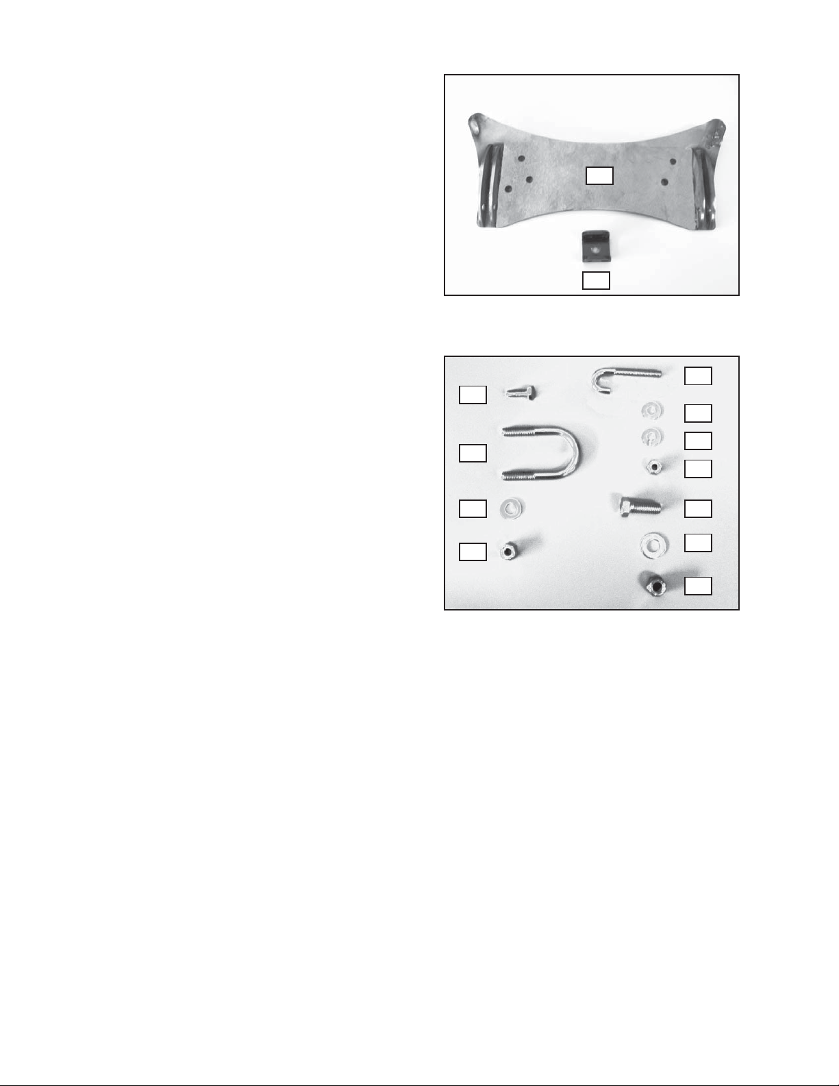
PROBLEM #1: Difficulty getting the U-Bolts (D1)
through both the skidplate and Plow Mount (A1).
SOLUTION #1: Remove the Plow Mount (A1) and
enlarge the holes in the skidplate by using a larger
drill bit or similar means. Reinstall the plow mount
with the U-bolts first and install the 5/16” Washer
(D2) and Nylock Nut (D3) to the ends of the U-
Bolts, but only thread the first few turns. Now align
the rear tabs and install the 6mm Bolt (B1), 1/4” Flat
Washer (C2), and 1/4” Lock Washer (C3). Tighten
all nuts and bolts securely.
THE PURPOSE OFTHE J-BOLT IS TO BREAK THE
CONNECTION BETWEEN THE PLOWAND THE WINCH
TO PREVENT SERIOUS DAMAGE TO THEATV IFTHE
PLOW IS RAISED TOO HIGH. THE PLOW BLADE WILL
DROPSUDDENLY IFTHE J-BOLT BREAKS, SO BE SURE
THATTHERE ARE NO BYSTANDERS WHENYOU RAISE/
LOWER THE PLOW. DO NOT RAISE THE TOPOFTHE
PLOWABOVE THE HEADLIGHTS OFTHEATVAS IT IS
NOT ONLY UNNECESSARY, BUT POTENTIALLY
DAMAGINGTO THE VEHICLEAND PLOW. IFYOU
NOTICE DEFORMATION OF THE J-BOLT, OR THE J-
BOLT IS BROKEN, REPLACE ITWITH THE SPARE J-
BOLT INCLUDED IN THE KIT.
WARNING
WARNING
11. Attach a 1/4” Flat Washer (C2) and 1/4” Nylock Nut (C4) to
the end of the J-Bolt (C1). Tighten the nut until the winch
cable loop is snug within the J-bolt hook. The completed
assembly should look like Figure 8.
Plow mount installation is now complete. Proceed to the next
section entitled “Maintenance/Care”.
that may inhibit the part from moving freely.
PERFORM REGULAR INSPECTIONS ON THE
PLOW, PLOW MOUNT,AND RELATED HARD-
WARE. NEVER OPERATE THE PLOWWITH
DAMAGED OR MISSINGPARTS. FAILURE TO
FOLLOW THIS WARNING MAY CAUSE VEHICLE
DAMAGEAND OPERATOR INJURYOR DEATH.
WARNING

Table of contents
Other Warn Automobile Accessories manuals