2
Installation Procedure
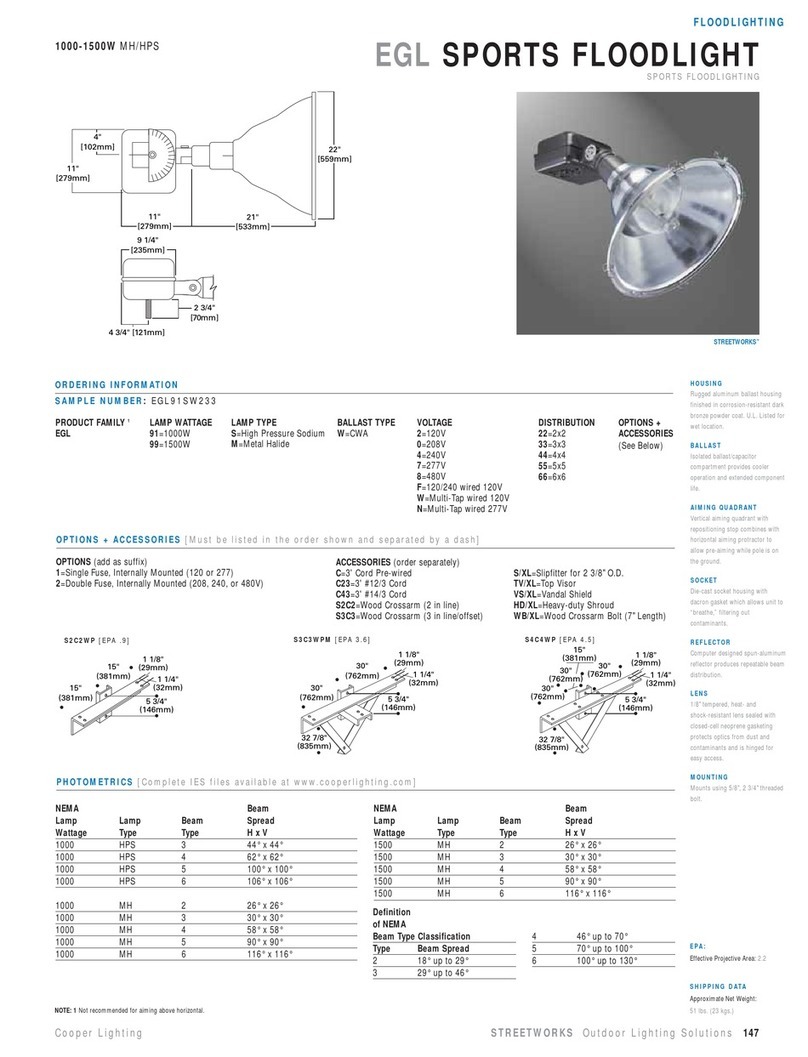
1) Switch off the mains electrical supply.
2) To open luminaire, release locking device A. Then
detach lens frame B.
3) Release quarter-turn fastener Cby turning it counter-
clockwise. Remove gear tray D. Detach male side of
terminal connector E.
4) Prepare enough cable to extend between luminaire
and column base. Feed cable through cable gland G.
a) Class I: Connect the mains supply leads to their
respective terminals in the terminal connector E.
(N = neutral, L1 = phase, = earthing).
b) Class II: Remove the cover of the cable connector E.
Connect neutral (N) and phase (L1) to the marked
contacts. Attach the cover and fix it. The connecting
cable must be double-insulated when inserting it into
the cable connector.
Check that rating shown on the luminaire label con-
forms with the mains electrical supply.
5) Tighten cable gland Gfirmly.
6) Match male to female side of terminal connector E.
Reposition gear tray D, and secure in position by turn-
ing quarter-turn fastener Cclockwise until it clicks
into place.
8) Fit in the appropriate lamp by inserting it firmly into
the lampholder.
7) Reposition lens frame B. Close it and secure in position
by means of locking device A.
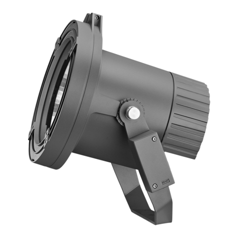
8) Attach mounting stirrup L to luminaire by means of
bolts J, and lock in desired position using hexagon
socket screw H.
9) Employ mounting stirrup L to mount luminaire to a
wall, column, bracket or other structure.
Secure in position by two M12 stainless steel bolts and
self locking nuts.
Vorgehensweise
1) Spannungsfreiheit der Anschlussleitung herstellen.
2) Verschluss Aöffnen.
3) Abdeckung Babklappen und aushängen.
4) Drehverschluss Centriegeln, Gerätechassis Dabklappen,
Steckverbindung Etrennen und Gerätechassis aus-
hängen.
5) Entsprechend der Masthöhe zugeschnittene Anschluss-
leitung durch die Kabelverschraubung Geinführen.
a) Schutzklasse I: Nulleiter (N), Phase (L1) und Schutz-
leiteranschluss an die entsprechend markierten
Kontakte des Steckverbinders Eanschließen.
b) Schutzklasse II: Entfernen der Abdeckung des Steck-
verbindes E. Nulleiter (N) und Phase (L1) an die mar-
kierten Kontakte anschließen. Die Abdeckung wieder
aufsetzen und befestigen. Das Anschlusskabel muss
doppelt isoliert in den Steckverbinder eingeführt werden.
Vergleichen Sie die örtliche Spannung und Frequenz
mit den Daten auf dem Leistungsschild.
6) Kabelverschraubung Gfestziehen.
7) Gerätechassis einhängen, Steckverbindung schließen,
Gerätechassis einklappen und verriegeln. Setzen Sie
ausschließlich den auf dem Leistungsschild ange-
gebenen Lampentyp ein.
8) Abdeckung einhängen, schließen und verriegeln.
9) Befestigen Sie den Bügel Lam Scheinwerfer mit Hilfe
der Innensechskantschraube Hund der zwei Rändel-
schrauben J.
10) Die Befestigung des Scheinwerfers am Mast hängt ab
vom Typ der gewählten Traverse.
Stellen Sie sicher, dass der Scheinwerfer mit zwei M12
Schrauben und selbstsichernden Muttern aus nichtros-
tendem Stahl an der Traverse befestigt wird.


