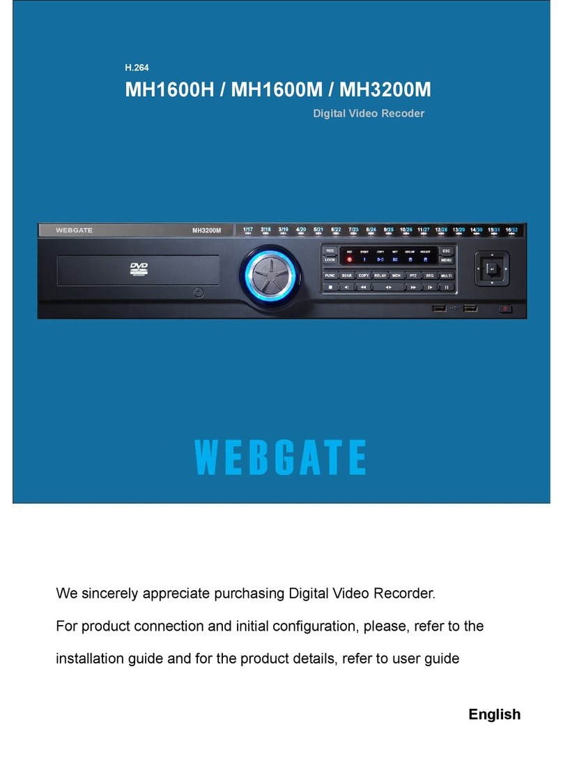
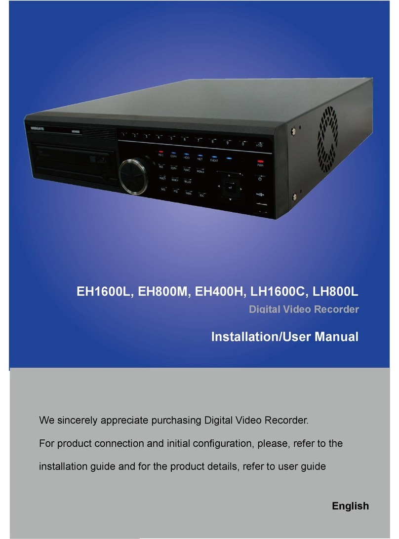
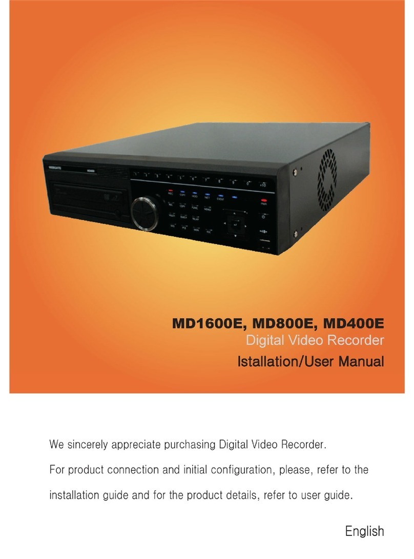
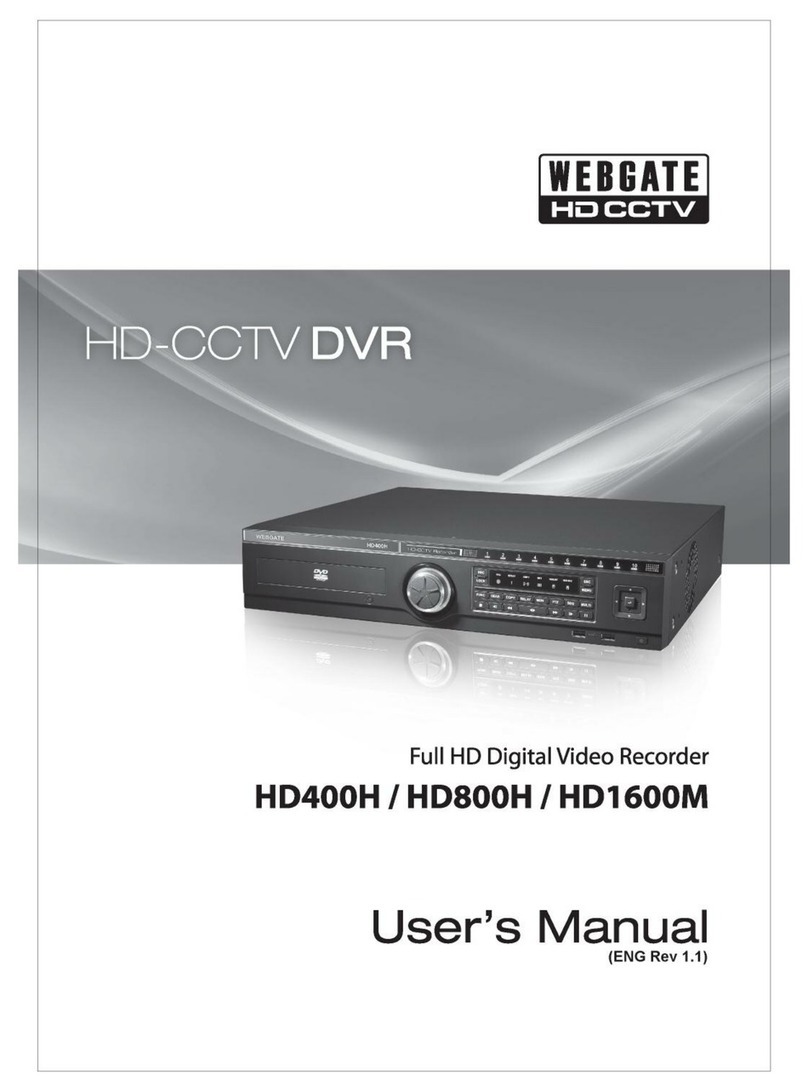
WebGate HD400H User manual


English
1
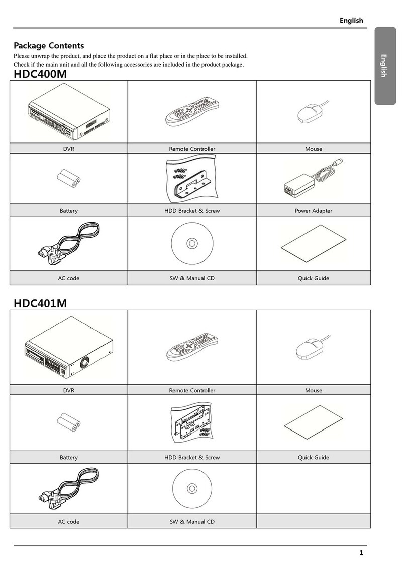
Package Contents
Please unwrap the product, and place the product on a flat place or in the place to be installed.
Check if the main unit and all the following accessories are included in the product package.
DVR
Remote Control
Mouse
Remote Control Battery (AAAx2)
Rack Bracket & Screws
HDD Installation Screws
Power Cable
CMS SW & User Manual CD
Quick Guide
User Manual
Before Starting
Please take note of the followings before using this prod.
Do not use the product in outdoor.
Do not spill water or liquid in the connection part of the product.
Do not impose excessive shock or force on the system.
Do not pull out the power plug forcefully.
Do not disassemble the product on your own.
Do not exceed the rated input/output range.
Use a certified power cord only.
For the product with an input ground, use a grounded power plug.
This equipment has been tested and found to comply with the limits for a Class A digital device, pursuant to part 15 of the FCC Rules.
These limits are designed to provide reasonable protection against harmful interference when the equipment is operated in a commercial
environment.
This equipment generates, uses, and can radiate radio frequency energy and, if not installed and used in accordance with the instruction
manual, may cause harmful interference to radio communications. Operation of this equipment in a residential area is likely to cause
harmful interference in which case the user will be required to correct the interference at his own expense.
Correct Disposal of This Product (Waste Electrical & Electronic Equipment)
(Applicable in the European Union and other European countries with separate collection systems)
This marking on the product, accessories or literature indicates that the product and its electronic accessories (e.g. charger, headset, USB
cable) should not be disposed of with other household waste at the end of their working life. To prevent possible harm to the environment
or human health from uncontrolled waste disposal, please separate these items from other types of waste and recycle them responsibly to
promote the sustainable reuse of material resources.
Household users should contact either the retailer where they purchased this product or their local government office, for details of where
and how they can take these items for environmentally safe recycling.
Business users should contact their supplier and check the terms and conditions of the purchase contract. This product and its electronic
accessories should not be mixed with other commercial wastes for disposal.
Correct disposal of batteries in this product
(Applicable in the European Union and other European countries with separate battery return systems.)
This marking on the battery, manual or packaging indicates that the batteries in this product should not be disposed of with other
household waste at the end of their working life. Where marked, the chemical symbols Hg, Cd or Pb indicate that the battery contains
mercury, cadmium or lead above the reference levels in EC Directive 2006/66. If batteries are not properly disposed of, these substances can
cause harm to human health or the environment.
To protect natural resources and to promote material reuse, please separate batteries from other types of waste and recycle them through
your local, free battery return system.
English

English오류! 알려지지 않은 문서 속성 이름입니다.
2
Wiring Diagram for External Devices
Connecting to the monitor
Check resolution of monitor before connection.
Using HDMI Port : 1920 x 1080p ( HDMI v1.2 Standard )
Using VGA Port : 1920 x 1080p CVT-RB ( VESA Standard )
<Note>
Make sure to use standard camera supporting HD-SDI standard. (HD-SDI)
Normal HDMI monitor and VGA monitor are not supported at the same time.
In case monitor supporting both 1080p and 1920x1080p CVT-RB they can be connected and
used at the same time.
Connecting camera
Connect DVR with HD-SDI cable using recommended coax cable.
Input video type is recognized upon turning on DVR.
There is no limitation on same resolution cameras but in case 1080p and 720p are mixed to input, 720p
must be connected on lower channel numbers while 1080p on higher number channel.
e.g. No. 1,2 channel 720p connection / No. 3,4 channel 1080p connection / No. 5,6 channel 720p
connection / No. 7,8 channel 1080p connection
Recommended cable
5C-FB(T), 5C-HFB(T), L-5CFB
L-4.5CHD, L-6CHD : HD-SDI customized cable
Cable type
HD-SDI transmission
distance
Remark
5C2V
about 100M
Cable for analog signal
4C-FB(T), 4C-HFB(T), RG59
about 150M
High-foamed cable, double or trishield
recommended
5C-FB(T), 5C-HFB(T), L-6CHD, RG6
about 200M
Customized for HD-SDI

English
3
Recoding Setting
[Continuous&Event Record] [Manual&Event Record]
Continuous & Event
The continuous recording will perform automatically under the Continuous & Event configured value after the
DVR booted.
Manual & Event
Manual record can be configured in “Program” of record menu and Manual / Event record is
available to Start/Stop with pressing [REC] button on front panel.
<Reference>
In case of Manual Setting, user needs to check recording indicate status on the front panel. If there are no
recording indicate please press REC button to start recording.
[Schedule] [Program]
Schedule Recording
Schedule recording is recording function based on schedule set by user. Please set DATE, TIME and Program.
Set record mode as “Schedule & Event”and set each DATE and TIME.
Program setup
Please setup resolution, frame rate or picture quality of each individual camera per channel in “Program menu” of
record setup. (Please refer to “record menu” for further explanation)
<Reference>
If recording set correctly, the “REC LED” indicator in front will be flickering. In addition,
it is marked [SCHEDULE] or [MANUAL] indicating that all channels are recording.
Copy
Press [COPY] button in Function menu and execute COPY menu. When back up device is connected correctly,
disk is recognized automatically as following image and it is processed in order selecting copy type -> Setting
copy section -> Selecting drive -> Copy execution
Menu Record Record
Menu Record Program

English오류! 알려지지 않은 문서 속성 이름입니다.
4
[DVD Copy] [EXE Copy] [AVI Copy]
Check the channel that you want to do copy.
All channel is selected as default.
Network Connection
Internet
Remote PCRemote PC Broadband
Router or Hub
Broadband
Modem
Network Setting
Ethernet
Set type as Ethernet and input IP, Netmask, Gateway, DNS provided by administrator.
The way to input is using directional key or mouse wheel.
ADSL(PPPoE)
Change type for Network menu into xDSL then go to xDSL menu.
Menu Network Network

English
5
Change Port in Ethernet (User must remember Port)
Enter ID and P/W in xDSL menu provided when registered in PPPoE .
Connection confirmed message comes in Status when connection to xDSL is successful.
Flexible IP
In case DVR use Flexible IP, user can connect to DVR and CMS by searching for IP address of DVR
automatically using WRS service. To activate WRS function, go to WRS menu then set “Time interval”, “Group
ID”and “WRS server address.
User can search for product with GRUP ID or SN and We recommend using user own GROUP ID to avoid
duplication.
In case user want to connect to DVR not by CMS but webviewer, user needs to register product to WNS
service and obtain domain address. Please go to www.mycam.to for more information.
Auto port forwarding
When using Internet Sharing device supporting UPnP, this function enables all connected DVR to do Port
forwarding and they can be connected to Internet with IP address of Internet Sharing device.
(1) Configure two DVRs with DHCP ON.
(2) Please, check if DVRs which are connected to Internet Sharing Device are allocated with official IP.
(3) Configure DVR port of DVR(A) and DVR(B) as 81 and 82 individually.
(4) Configure UPnP function of Internet Sharing Device as “ON”.
(5) Configure UPnP Port Forwarding function of DVR as “ON”.
(6) Please, check if Port Forwarding Status message is changed from “Not Available”to “Port Mapping is
OK”.
(7) Finally, if user accesses DVR(A) with the IP address with port number 81 or DVR(B) with the IP address
with port number 82, user can access DVRs.
Manual port forwarding
User has to set port in the router in case user use router which doesn’t support UPnP function.
(1) Connect default IP address of the router.
(2) Go to “Port range forward”setup page in router manual.
(3) Set DVR IP address & Port of DVR connected to router then check ‘Enable’and save.
(4) Connect using DVR setup port of router address in the PC using same router. (DVR default port : 80).
(5) Check internet address of router to access to DVR from external PC.
English오류! 알려지지 않은 문서 속성 이름입니다.
6
(6) Connect to DVR setup port of internet address in router.
(7) Webviewer installer downloader will be running once connection to DVR is achieved.
And install ‘Webviewer installer’ to see DVR Webviewer login page.
(8) Enter USER ID and PASSWORD to enter monitoring page.

Other manuals for HD400H
1
This manual suits for next models
2
Table of contents
Other WebGate DVR manuals

WebGate
WebGate Hybrid DVR Series User manual

WebGate
WebGate DS412 User manual

WebGate
WebGate HS1620F-PD User manual

WebGate
WebGate MD1600L eDVR User manual

WebGate
WebGate MD1600H User manual

WebGate
WebGate HS1600F-D User manual

WebGate
WebGate eDVR MD800M User manual

WebGate
WebGate HDC400M User manual

WebGate
WebGate MD1600E User manual

WebGate
WebGate MD1600L eDVR User manual