4 5 6 Edition 3 / 08-2020
7. Grounding Ethernet Switch
ATTENTION
- Grounding and wire routing help limit the effects of noise due to
electromagnetic interference (EMI).
- the ground connection from the ground screw to the grounding surface
prior to connecting devices.
- This product is intended to be mounted to a well-grounded mounting
surface, such as a metal panel.
- The shielding ground of the RJ45 ports are electrically connected to the
ground connection (screw).
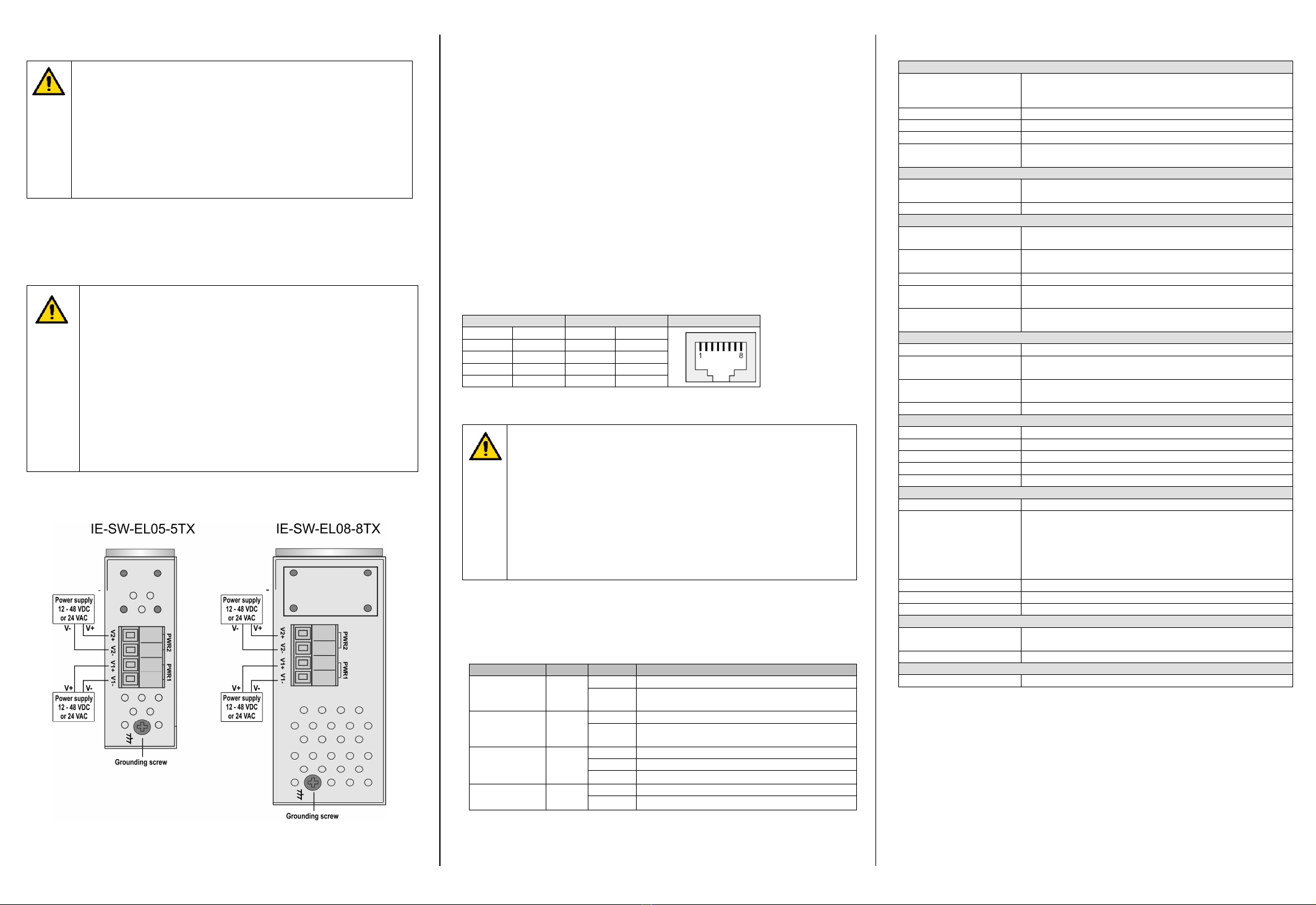
8. Wiring the Redundant Power Inputs
The switch supports redundant power supply inputs which are located on the 4-pin
terminal block. Refer to illustration below for correct wiring.
Warning / Avertissement
Take into consideration the following guidelines before wiring the device
oTenez compte des directrices suivantes avant de câbler l’appareil.
Terminal block is mating with Plug and suitable for 12-24AWG. Torque
value 4.5 lb-in.
oLe bornier est compatible avec les connecteurs et convient pour 12-
24AWG. Valeur de couple 4,5 lb-in.
The temperature rating of the input connection cable should higher than
105°C.
oLa température de service nominale du câble d’entrée doit être
supérieure à 105 °C.
Supplied by SELV source evaluated by UL 61010-1 or 61010-2-201
power supply only.
oFourni par la source SELV évaluée uniquement par l'alimentation UL
61010-1 or 61010-2-201.
9. Communication Connections
Switch IE-SW-EL05-5TX is equipped with following communication interfaces:
5x 10/100Base-T(X) ports
Switch IE-SW-EL08-8TX is equipped with following communication interfaces:
8x 10/100Base-T(X) ports
Please only use cables suitable for the respective type of communication and ensure that
signals are protected from possible interference.
9.1 10/100Base T(X) RJ45 Ports
The 10/100BaseT(X) ports located on Ethernet Switch’s front panel are used to connect
to Ethernet-enabled devices. Below we show pinouts for both MDI (NIC-type) ports and
MDI-X (HUB/Switch-type) ports. Auto MDI-X ensures that both wiring-schemes are
supported. (Automatic crossover function)
Each RJ45 Ethernet port independently supports auto-negotiation for recognizing the
transmission speed 10 Mbps or 100 Mbps according to the IEEE802.3 standard. This
means that some of connected Ethernet devices could operate at 10 Mbps, while at the
same time other nodes are operating at 100 Mbps.
10/100Base T(X) RJ45 Pinouts
MDI Port Pinouts MDI-X Port Pinouts 8-pin RJ45
Pin Signal Pin Signal
1 Tx+ 1 Rx+
2 Tx- 2 Rx-
3 Rx+ 3 Tx+
6 Rx- 6 Tx-
Note about possible loss of data packages in case of “Duplex
mismatching”
If the switch’s auto-negotiation port is connected to a non-negotiating device,
then the switch will set its port transmission speed same as the connected
device but is unable to correctly detect the duplex mode.
As result the port is set to the correct speed but is using always the half
duplex mode as required by the IEEE 802.3u standard in such cases.
For correct transmission, the non-negotiating port must be set to half-duplex
mode (speed can be either 10 Mbps or 100 Mbps, it always will be recognized
automatically by an Auto-Negotiation-Device).
10. LED Indicators
The front panel of the Ethernet Switch contains several LED indicators. The function of
each LED is described in the table below.
LED Color Status Description
PWR1 Green
On Power is being supplied to power input PWR1.
Off Power is not being supplied to power input
PWR1.
PWR2 Green
On Power is being supplied to power input PWR2.
Off Power is not being supplied to power input
PWR2.
LNK/ACT Green
On Port’s link is active.
Off Port’s link is inactive.
Blinking Transmitting data.
10/100M Amber On Port speed is 100 Mbps
Off Port speed is 10 Mbps
11. Specifications
Technology
Standards
IEEE 802.3 for 10Base-T
IEEE 802.3u for 100Base-TX
IEEE 802.3x for Flow Control
Processing Type Store and Forward
MAC Table size 1K
Packet buffer size 448 Kbit
Backplane bandwidth IE-SW-EL05-5TX: 1 Gbps
IE-SW-EL08-8TX: 1.6 Gbps
Interface
RJ45 Ports 10/100BaseT(X) auto negotiation speed, F/H duplex mode
and auto MDI/MDI-X connection
LED Indicators PWR1, PWR2 (Power), Port Link/Activity, Port Speed
Power
Input Voltage 24 V DC (12 - 48 V DC), 24 V AC (18 -36 V AC),
2 redundant inputs
Input Current @24 VDC IE-SW-EL05-5TX: 0.10 A
IE-SW-EL08-8TX: 0.14 A
Connection One removable 4-pin terminal block, Wiring cable 12-24AWG
Overload Current
Protection Present
Reverse Polarity
Protection Present
Physical Characteristics
Housing IP30 protection, metal
Dimension (W x H x D) IE-SW-EL05-5TX: 26.1 x 95 x 70 mm (1.03 x 3.74 x 2.76 in)
IE-SW-EL08-8TX: 41 x 95 x 90 mm (1.61 x 3.74 x 3.54 in)
Weight IE-SW-EL05-5TX: 205 g
IE-SW-EL08-8TX: 334 g
Installation DIN-rail
Environmental conditions
Operating Temperature -40 to 75°C (-40 to 167°F)
Storage Temperature -40 to 85°C (-40 to 185°F)
Ambient Relative Humidity
5 to 95% (non-condensing)
Altitude up to 2000 m
Pollution Degree 2
Regulatory Approvals
Safety UL 61010-1; UL 61010-2-201
EMC
EN 55032, EN 55024, FCC Part 15 Subpart B Class A,
IEC 61000-4-2 ESD: Contact: 4 kV; Air: 8 kV,
IEC 61000-4-3 RS: 80 MHz to 1 Ghz: 3 V/m,
IEC 61000-4-4 EFT: Power: 0.5 kV; Signal: 0.5 kV,
IEC 61000-4-5 Surge: Power: 0.5 kV; Signal: 1 kV,
IEC 61000-4-6 CS: 3 Vrms
Shock IEC 60068-2-27
Free Fall IEC 60068-2-31
Vibration IEC 60068-2-6
MTBF
Time IE-SW-EL05-5TX: 2.638.236 hrs
IE-SW-EL08-8TX: 1.390.019 hrs
Database Telcordia SR332
Warranty
Time Period 5 years
Contact Information
Weidmüller Interface GmbH & Co. KG
Klingenbergstraße 26, 32758 Detmold / Germany
Phone +49 (0) 5231 14-0, Fax +49 (0) 5231 14-292083
E-Mail weidmueller@weidmueller.com, Internet www.weidmueller.com


