4 5 6 V1.2 / 2022-03-29
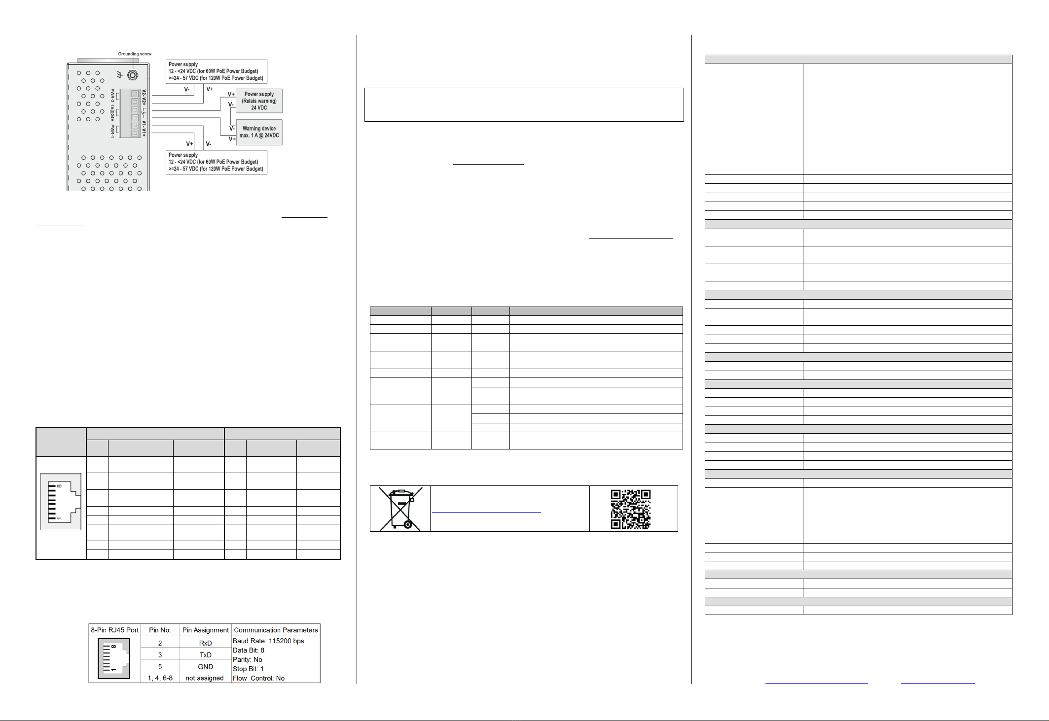
Refer to illustration below for correct wiring.
Behavior of fault alarm relay (can be triggered by configurable events power failure or
port link down):
Relay contact is closed if the device is powered-off.
Relay contact is open if the device is powered-on and no alarm conditions exist (neither
Power Failure Alarms nor Port Link Loss Alarms are activated (Web menu Warnings
Fault Relay Alarm).
Relay contact closes if any of an activated alarm condition happens.
9. Communication Connections
Switch IE-SW-AL08M-8GTPoE is equipped with 8 x 10/100/1000BASE-T(X) PoE ports (P.S.E.)
Please only use cables suitable for the respective type of communication and ensure that
signals are protected from possible interference.
9.1 10/100/1000BASE-T(X) PoE ports (P.S.E)
For communication without PoE sourcing the switch supports auto negotiation speed,
Full/Half duplex mode and auto MDI/MDI-X connection, means automatic setting of pinouts
for both MDI ports (NIC-type) or MDI-X ports (HUB/Switch-type).
In case of active PoE sourcing the switch uses the pinout of “Alternative A, MDI mode” of
802.3af/802.3at standards. Please see the details in the following table.
Pinouts 10/100/1000BASE-T(X) PoE ports (P.S.E)
8-Pin RJ45
Port
10/100 BASE-T(X) MDI/MDI-X 1000BASE-T MDI/MDI-X
Pin
No. MDI port MDI-X port Pin
No. MDI port MDI-X port
1 TD+(transmit) with
PoE Power + RD+(receive) 1 BI_DA+ with
PoE Power + BI_DB+
2 TD-(transmit) with
PoE Power + RD-(receive) 2 BI_DA- with
PoE Power + BI_DB-
3 RD+(receive) with
PoE Power - TD+(transmit) 3 BI_DB+ with
PoE Power - BI_DA+
4 Not used Not used 4 BI_DC+ BI_DD+
5 Not used Not used 5 BI_DC- BI_DD-
6 RD-(receive) with
PoE Power - TD-(transmit) 6 BI_DB- with
PoE Power - BI_DA-
7 Not used Not used 7 BI_DD+ BI_DC+
8 Not used Not used 8 BI_DD- BI_DC-
9.2 RS232 Console Port
The RS232 Interface with RJ45 connector can be used to access the switch console for
configuration. Additionally, it can be applied with external Backup/Restore module IE-EBR-
MODULE-RS232-ALM (Article no. 2682610000).
Pinouts Serial
Console Port:
10. User Management
10.1 Device Access (Login to Web Interface)
The Web interface of the Switch can be accessed via following factory default settings:
IP address / Netmask: 192.168.1.110 / 255.255.255.0
User name: admin
Password: Detmold
Connect the PC to any Ethernet port of the managed Switch and set the PC’s IP
address to a free one of range 192.168.1.0 / 255.255.255.0
Start a web browser and enter the IP address of the connected Switch into the
browser’s address line (http://192.168.1.110). After the appearance of prompt (login)
enter the login credentials. After confirmation of your input with "OK" the home page of
the switch will be displayed.
10.2 Reset Button (Behavior of Factory Default Settings)
Pressing < 5 seconds: Reboot the switch (Warm Start) and sets IP to Factory
Default IP.
Pressing >= 5 seconds: Resets the switch configuration to Factory Default Settings.
Note: Behavior of reset button can be configured in the Web Interface (Menu Factory Default).
11. LED Indicators
The front panel of the Ethernet Switch contains several LED indicators. The function of
each LED is described in the table below.
LED Color Status Description
PWR1 Green On Power is supplied to power input PWR1.
PWR2 Green On Power is supplied to power input PWR2.
R-MSTR
(Ring Master) Green On Is Ring Master of an enabled O-Ring.
Ring Green On O-Ring redundancy is enabled.
Blinking Ring structure is broken (No redundancy).
PoE Green On Power supplied over Ethernet
LNK/ACT Green
On Port link is active.
Off Port link is inactive.
Blinking Data is transmitted.
10/100/1000M Green /
Amber
Green Port speed is set to 1000 Mbps.
Amber Port speed is set to 100 Mbps.
Off Port speed is set to 10 Mbps.
FAULT Amber On Fault Relay indication for Power failure and Port
link loss.
12. Disposal Information
Observe the notes for proper disposal of the
product. You can find the notes here:
www.weidmueller.com/disposal.
13. Specifications
Technology
Ethernet Standards
IEEE 802.3 for 10BASE-T
IEEE 802.3u for 100BASE-TX
IEEE 802.3ab for 1000BASE-T
IEEE 802.3x for flow control
IEEE 802.3af/at for Power over Ethernet
IEEE 802.3ad for port trunk with LACP
IEEE 802.1D for STP (Spanning Tree protocol)
IEEE 802.1w for RSTP (Rapid Spanning Tree protocol)
IEEE 802.1s for MSTP (Multiple Spanning Tree Protocol)
IEEE 802.1p for Class of Service
IEEE 802.1Q for VLAN Tagging
IEEE 802.1x for Authentication
IEEE 802.1AB for LLDP (Link Layer Discovery Protocol)
Processing Type Store and Forward
MAC Table size 8K
Packet buffer size 4 Mbit
Backplane bandwidth 16 Gbps
Jumbo frame support up to 9.6 kBytes
Interfaces
RJ45 Ports 10/100/1000BASE-T(X) PoE ports (P.S.E.) compliant to PoE
standard IEEE 802.3af/at
RS232 Console Port RS232 Interface with RJ45 connector for Console access and
useable with external Backup/Restore module
LED Indicators PWR1, PWR2 (Power), Fault (Relay), Ring Master, Ring
Status, Port Link/Activity/Speed, PoE
Relay Contact Max. 1A @ 24 V DC for Power Failure and Port Link Loss
Power
Input Voltage 12/24/48 V DC (12 - 57 V DC), 2 redundant inputs
Input Current
(with PD consumption)
6.53 A @ 12 V DC; 5.49 A @ 24 V DC; 2.68 A @ 48 V DC
Connection One removable 6-pin terminal block, Wiring cable 12-24AWG
Overload Current Protect. Present
Reverse Polarity Protect. Present
PoE
Total power budget 60 W @ 12 – <24 V DC; 120 W @ 24 - 57 V DC
PoE Pinout Mode A: Pin 1, 2 (V+); Pin 3, 6 (V-); Alternative A; MDI
Physical Characteristics
Housing IP30 protection, metal
Dimension (W x H x D) 54.3 x 145.1 x 108.5 mm (2.14 x 5.71 x 4.27 inch)
Weight 678 g
Installation DIN-rail
Environmental conditions
Operating Temperature -40 to 75°C (-40 to 167°F)
Storage Temperature -40 to 85°C (-40 to 185°F)
Ambient Relative Humidity 5 to 95% (non-condensing)
Operating Altitude Up to 2000 m
Regulatory Approvals
Safety UL 61010-1; UL 61010-2-201
EMC
EN 55032, EN 55024, FCC Part 15 Subpart B Class A,
IEC 61000-4-2 ESD: Contact: 4 kV; Air: 8 kV,
IEC 61000-4-3 RS: 80 MHz to 1 Ghz: 3 V/m,
IEC 61000-4-4 EFT: Power: 0.5 kV; Signal: 0.5 kV,
IEC 61000-4-5 Surge: Power: 0.5 kV; Signal: 1 kV,
IEC 61000-4-6 CS: 3 V
Shock IEC 60068-2-27
Free Fall IEC 60068-2-31
Vibration IEC 60068-2-6
MTBF
Time 495.670 hrs
Database Telcordia SR332
Warranty
Time Period 5 years
Contact Information
Weidmüller Interface GmbH & Co. KG
Klingenbergstraße 26, 32758 Detmold / Germany
Phone +49 (0) 5231 14-0, Fax +49 (0) 5231 14-292083
E-Mail weidmueller@weidmueller.com, Internet www.weidmueller.com


