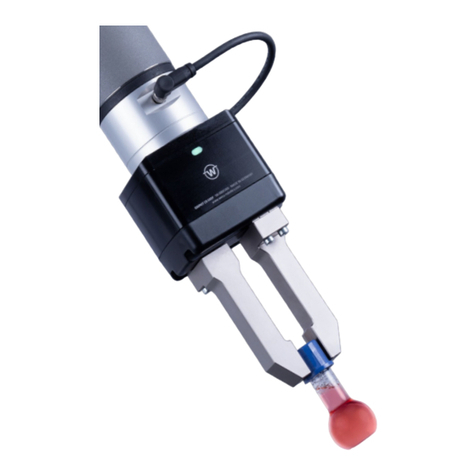
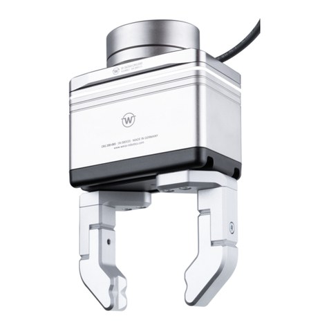
WEISS ROBOTICS GRIPKIT CR EASY User manual

Collaborative servo-electric gripping module
GRIPKIT CR EASY
April 2021

- 1 -
Content
1 Introduction........................................................................................................................ 2
1.1 Notation and symbols......................................................................................................... 2
1.2 Product description............................................................................................................. 2
1.3 Related documents............................................................................................................. 3
1.4 Target groups...................................................................................................................... 3
2 Basic safety instructions ..................................................................................................... 4
2.1 Intended use....................................................................................................................... 4
2.2 Ambient and operating conditions..................................................................................... 4
2.3 Product safety..................................................................................................................... 4
2.4 Personnel qualification ....................................................................................................... 5
2.5 Safety conscious work......................................................................................................... 5
2.6 Notes on special hazards .................................................................................................... 5
3 Warranty............................................................................................................................. 6
4 Scope of delivery and accessories ...................................................................................... 7
5 Technical data..................................................................................................................... 8
5.1 Mechanical nominal data ................................................................................................... 8
5.2 Electrical nominal data ..................................................................................................... 11
6 Assembly instruction......................................................................................................... 15
7 Configuration of the gripping module .............................................................................. 16
7.1 Referencing....................................................................................................................... 17
7.2 Parameterization of a grip ................................................................................................ 17
8 Create applications ........................................................................................................... 19
9 Maintenance and cleaning................................................................................................ 20
9.1 Adjustment of the maintenance interval.......................................................................... 21
10 Troubleshooting................................................................................................................ 21
10.1 Base jaws do not move..................................................................................................... 21
10.2 Gripping module stops abruptly or does not travel the entire stroke ............................. 22
11 EC Declaration of Incorporation ....................................................................................... 23
- 2 -
1Introduction
These instructions are part of the gripping module and describe its safe and proper use in all operating
phases. They are exclusively valid for the gripping module GRIPKIT CR EASY and contain important
information on installation, commissioning, maintenance and service.
1.1 Notation and symbols
For a better overview, the following symbols are used in these instructions:
Function or safety-relevant note. Non-observance may endanger the safety of personnel
and plant, damage the device or impair the function of the device.
Additional information for a better understanding of the described facts.
Reference to further information.
1.2 Product description
The GRIPKIT CR EASY gripping module is a collaborative, servo-electric gripping module with innovative
gripping force control and digital IO interface. Fehler! Verweisquelle konnte nicht gefunden werden.
and Figure 2 show the connections and components of a GRIPKIT CR EASY gripping module. The
gripping module is optionally configured via the configuration tool “GRIPKIT Easy Configurator”
available at www.weiss-robotics.com/cr-easy.
Figure 1: Components and connections of the gripping module (top view)
Base jaw
Status display

- 3 -
Figure 2: Components and connections of the gripping module (bottom view)
1.3 Related documents
Further documents for the operation of the gripping module are available for download on our website
at www.weiss-robotics.com/cr-easy.
For additional warranty information, please refer to our General Terms and Conditions, available at
www.weiss-robotics.com/agb.
1.4 Target groups
The target group for these instructions are, on the one hand, plant manufacturers and operators who
should keep this and other documents supplied accessible to personnel at all times and, in addition,
encourage them to read and observe the safety and warning instructions in particular.
In addition, it is intended for qualified personnel and fitters who should read these instructions and
observe and comply with the safety and warning instructions at all times.
electrical connection
Mounting plate
Base body
Protective cover
USB port

- 4 -
2Basic safety instructions
2.1 Intended use
The gripping module is designed for gripping and reliably holding workpieces or objects and is intended
for installation in a machine. The requirements of the applicable directives as well as the assembly and
operating instructions in this manual must be observed and complied with. The gripping module may
only be used within the scope of its defined application parameters and only in industrial applications.
Any other use or use beyond this is considered improper, e.g. if the gripping module is used as a
pressing, cutting, lifting or punching tool or as a clamping device or guiding aid for tools. The
manufacturer is not liable for any damage resulting from this.
2.2 Ambient and operating conditions
The gripping module may only be used within its defined application parameters. It must be ensured
that the gripping module and the fingers are sufficiently dimensioned according to the application, and
that the environment is clean and the ambient temperature corresponds to the specifications in the
data sheet. Observe the maintenance instructions (see chapter 9). Furthermore, it must be ensured
that the environment is free of splash water and vapors as well as abrasion or process dusts. Exceptions
to this are gripping modules that are specially designed for dirty environments.
2.3 Product safety
The gripping module corresponds to the state of the art and the recognized safety rules at the time of
delivery. However, hazards may emanate from it if, for example:
•the gripping module is not used as intended
•the gripping module is improperly mounted, modified or incorrectly maintained
•the EC Machinery Directive, the VDE Directives, the safety and accident prevention regulations
applicable at the place of use or the safety and assembly instructions are not observed
2.3.1 Protective devices
Protective devices must be provided in accordance with the EC Machinery Directive.
2.3.2 Structural changes, additions and conversions
Additional holes, threads or attachments that are not offered as accessories by Weiss Robotics may
only be attached after written approval by Weiss Robotics.

- 5 -
2.3.3 Special standards
The following standards are complied with:
•Radio interference voltage, interference field strength and radiation according to EN 61000-6-
3
•Fast transients on signal and data lines according to EN 61000-4-4
•HF current injection on signal and data lines according to EN 61000-4-6
•RF irradiation according to EN 61000-4-3
•Interference emission according to EN 61000-6-4 Class A
•Magnetic field with power frequency according to EN 61000-4-8
•Discharge of static electricity according to EN 61000-4-2
2.4 Personnel qualification
Installation, initial startup, maintenance and repair of the gripping module may only be performed by
trained specialists.
Every person assigned by the operator to work on the gripping module must have read and understood
the complete operating manual, in particular chapter 2 “Basic safety instructions”. This also applies to
personnel who are only occasionally deployed, for example maintenance personnel.
2.5 Safety conscious work
Observe the safety and accident prevention regulations applicable at the place of use.
Do not move any parts by hand when the power supply is connected.
Do not reach into the open mechanics and the movement range of the gripping module.
Disconnect the power supply of the gripping module before carrying out any work.
2.6 Notes on special hazards
Risk of injury from falling and ejecting objects!
Provide guards to prevent falling or ejection of objects, for example, machined
workpieces, tools, chips, fragments, waste.
Risk of injury due to unexpected movements of the machine/plant!

- 6 -
3Warranty
The warranty period is 12 months from the date of delivery to the factory, assuming proper use in
single-shift operation and observance of the prescribed maintenance and lubrication intervals or 10
million gripping cycles. Parts in contact with the workpiece and wear parts are not covered by the
warranty. Please also refer to the General Terms and Conditions (GTC).
The gripping module is considered defective if its basic function, gripping, is no longer available.

- 7 -
4Scope of delivery and accessories
The scope of delivery includes the parts listed in Table 1.
Table 1: Scope of delivery
Designation
Part number
Gripping module GRIPKIT CR EASY
5010018
Connecting cables gripping module
5070018
USB cable, A male to Micro-B male (1.8 m)
4020023
GRIPKIT CR EASY accessory pack
5020066
Quick Start Guide GRIPKIT CR EASY
5080031
Safety instructions
5080032
The following accessories are available separately for the gripping module:
•Connection lines
•Gripping fingers
GRIPKIT CR EASY does not contain any gripping fingers, as these are usually highly application-
dependent.
Accessories can be ordered separately.
Additional accessories can be found on our website at www.weiss-robotics. com.

- 8 -
5Technical data
5.1 Mechanical nominal data
If the specified nominal data are exceeded, the gripping module may be damaged. In
case of doubt, clarify your application with our technical sales department.
Table 2: Mechanical nominal data
Designation
Unit
Value
Total stroke
mm
30
Nominal gripping force (100%)
N
200
Recommended minimum gripping force (25%)
N
50
Max. relative finger speed
mm/s
140
Min. relative finger speed
mm/s
10
Dead weight
g
830
Workpiece weight (form closure/force
closure)
g
4300/1000
Permissible finger length (L)1
mm
100
Permissible mass per finger
g
300
Protection class
-
IP 40
Ambient temperature
°C
5 to 50
Humidity
%
0 to 90, non-condensing
Mechanical repeatability
mm
±0,03
Resolution of the displacement encoder
mm
0,01
Mode of operation of the displacement
encoder
-
Relatively
1
At nominal force; further details in chapter 5.1.1

- 9 -
5.1.1 Permissible finger length
The permissible finger length L corresponds to the distance between the screw-on surface of the base
jaw and the effective gripping force application point, see Figure 3. Maximum values for L can be taken
from the mechanical nominal data of the size used.
If the maximum finger length is exceeded, a reduction of the gripping force is mandatory.
In addition, this can shorten the service life of the gripping module.
Figure 3: Determination of finger length L. Left: straight fingers, right: cranked fingers.
5.1.2 Gripping force and finger speed
The gripping force can be set as a percentage of the nominal gripping force. The recommended
minimum gripping force is 25% of the nominal gripping force.
5.1.3 Cycle times
The following diagrams show the typical course of the gripping duration and the release duration for
different gripping force settings.
The values shown indicate the typical duration from the processing of the command at
the gripping module to the change of the gripping state. The actual duration varies
depending on the gripping part (rigid or elastic), finger weight, grip height, etc.
For a more precise estimation of the possible cycle times, tests must be carried out in
individual cases.
L
L

- 10 -
Figure 1: Gripping time as a function of stroke
Figure 2: Release duration depending on stroke
5.1.4 Permissible finger loads
The following table shows the permissible static loads on the base jaw guide.
Table 3: Static guide loads
Last
Unit
Value
C0
N
1890
Tx
Nm
6,9
Ty
Nm
26,0
Tz
Nm
23,6

- 11 -
In the case of superimposed forces and moments, the load carrying capacity of the guide must be
recalculated according to equation (12)
(12)
Here, C0and Tare the permissible guide loads according to Table 3 and Mis the sum of all moments
occurring at each base jaw (gripping, weight, inertia and process forces) in the application. The
moments are plotted in Figure 3.
Figure 3: Finger loads
5.2 Electrical nominal data
If the specified nominal data are exceeded, the gripping module may be damaged. In
case of doubt, clarify your application with our technical sales department.
Table 4: Electrical nominal data
Designation
Unit
Value
Supply voltage
V
18 up to 30
Typ. current consumption (state INACTIVE)
mA
60
Mx
My
Mz
Fz

- 12 -
Typ. current consumption (HOLDING state, 100% gripping force)
mA
300
Max. current consumption (moving, peak current)
mA
500
Digital inputs
Max. Signal voltage (active high)
V
30
Min. signal voltage (active low)
V
0
Digital outputs
Signal voltage (signal "HIGH")
V
24
Signal voltage (signal "LOW")
V
0
Max. Signal current
mA
100
Table 5: Electrical ratings of the USB port
Designation
Unit
Value
Supply voltage
V
5
Type. Current consumption
mA
50
5.2.1 Electrical interface
The gripping module has a ten-pin PCB terminal for electrical contacting. It is attached to the underside
of the flange and shown in Figure 4. The pin assignment is listed in Table 6.

- 13 -
Figure 4: Connection terminal on the underside of the flange
Table 6: Terminal assignment
Pin
Function
1
Not connected
2
IN 1
3
IN 0
4
Not connected
5
Not connected
6
GND
7
+24 V/1.5 A IN
8
Not connected
9
OUT 1
10
OUT 0
5.2.2 Switching signals of the digital inputs
The inputs IN 0 and IN 1 of the gripping module support both NPN and PNP signals. The passive state
is detected when the input is not actively driven (inactive). The active state is detected when the input
is actively driven with either 0 V (NPN, “sinking”) or 24 V (PNP, “sourcing”). The function of the inputs
is listed in Table 7.

- 14 -
Table 7: Function of inputs IN 0 and IN 1
Input
Signal Inactive
Signal Active
IN 0
Gripper deactivated
Gripper activated
IN 1
Release workpiece2
Grip workpiece2
5.2.3 Switching signals of the digital outputs
The gripping module signals the current gripping state via the digital outputs. The outputs are designed
as push-pull circuit. Table 8 shows the coding of the state.
Table 8: Coding of the gripping state via the digital outputs
State OUT 1
State OUT 0
Gripping state
0 V
0 V
Gripper deactivated or error present (IDLE, ERROR)
0 V
24 V
Workpiece released (RELEASED)
24 V
0 V
No workpiece detected (NO PART)
24 V
24 V
Workpiece gripped (HOLDING)
5.2.4 Fusible link to protect against increased gripping force
The gripping module is equipped with a fuse to protect the operator from impermissibly high gripping
forces. This fuse is a safety-related component and must not be replaced/modified under any
circumstances.
If the fuse has tripped, the gripping module must be sent to WEISS ROBOTICS for repair.
2
The preconfigured grip parameters are used. See chapter 7.

- 15 -
6Assembly instruction
Only use the screws and dowel pins supplied to mount the gripping module.
1. Plug the enclosed cable, suitable for the robot used, into the flange.
2. Insert the cylindrical pin (Ø 6mm) into the flange and position it on the robot.
3. Screw the flange to the robot.
4. Insert the two dowel pins (Ø 4mm) into the flange.
5. Screw the gripping module to the flange.
6. Connect the connection cable to the robot
During assembly, also observe the robot-specific mechanical properties of the tool
flange.

- 16 -
7Configuration of the gripping module
To configure your gripping module, you need the “GRIPKIT Easy Configurator”program and a
Windows-compatible computer. The program is available for download at www.weiss-
robotics.com/cr-easy. Install the program and open it afterwards.
Connect the gripping module to your computer with the included USB cable (A connector to Micro-B
connector). The voltage supply of the gripping module is also external during configuration. For this
purpose, the connection cable must be connected to the robot and its voltage output must be
activated.
Figure 5: Connecting the gripping module for configuration
Make sure that during configuration the gripping module does not pose any danger due
to careless gripping or release.
Now start the “GRIPKIT Easy Configurator”program and connect the gripping module by clicking on
the “Connect”button.

- 17 -
Figure 6: Establishing a connection with the gripping module
7.1 Referencing
The gripping module may have to be referenced after the connection has been established. To do this,
click on the “Home”button. Depending on the grip parameters set, referencing is performed inwards
(option “Inside”activated) or outwards (option “Outside”activated). After successful referencing, the
state changes to IDLE.
7.2 Parameterization of a grip
By adjusting the sliders or entering the values in the input fields, you can set the grip parameters. With
a click on the “Save”button, the parameters are stored non-volatile on the gripping module.
A grip consists of a position window with the limit values “Release Limit”and “No Part Limit”. When
releasing, the gripper jaws are moved up to the Release Limit, the gripping state changes to RELEASED.
During gripping, the gripper jaws are moved up to a maximum of the “No Part Limit”. If a component
is gripped and held before this, the gripping state changes to HOLDING. If no component is gripped up
to the “No Part Limit”, the status changes to NO PART.
You can use the “Grip”and “Release” keys to test the currently set parameters.

- 18 -
Figure 7: Configuration and test of the gripping parameters
7.2.1 Gripping direction
The gripping direction is determined by the relation of the position limit values to each other. If the
“No Part Limit” limit value is greater than the “Release Limit”, an inside grip is executed, but if the
“Release Limit”limit value is greater than the “No Part Limit”, an outside grip is executed.
When gripping and releasing, electric gripping modules stop at the positions
“No Part Limit”or “Release Limit”.
Figure 8: Outer grip and inner grip
7.2.2 Gripping force
GRIPKIT CR EASY has an integrated gripping force control. The gripping force can be specified as a
percentage depending on the nominal gripping force of the gripping module.

- 19 -
7.2.3 Diagnostic data
Under the “Diagnostics”tab, you will find the firmware version used, a temperature display and
warnings about the status of the gripping module.
Figure 9: Diagnostic data
If you detect a problem with your gripping module, first connect it to a computer and
read out the diagnostic data via the “GRIPKIT-Easy Configurator”.
8Create applications
The gripping module is used in a robot program according to the instructions of the plug-in software
available for the robot used.
Other manuals for GRIPKIT CR EASY
2
This manual suits for next models
2
Table of contents
Other WEISS ROBOTICS Robotics manuals

WEISS ROBOTICS
WEISS ROBOTICS GRIPKIT CR EASY User manual

WEISS ROBOTICS
WEISS ROBOTICS GRIPKIT CR PLUS Series User manual

WEISS ROBOTICS
WEISS ROBOTICS CRG Series Technical document

WEISS ROBOTICS
WEISS ROBOTICS GRIPLINK-ET4 User manual

WEISS ROBOTICS
WEISS ROBOTICS IEG Series Technical document

WEISS ROBOTICS
WEISS ROBOTICS GRIPLINK User manual

WEISS ROBOTICS
WEISS ROBOTICS GRIPKIT CR PLUS User manual

WEISS ROBOTICS
WEISS ROBOTICS GRIPKIT CR EASY User manual

WEISS ROBOTICS
WEISS ROBOTICS GRIPLINK-ET4 User manual

WEISS ROBOTICS
WEISS ROBOTICS GRIPKIT CR PLUS User manual