WELDY foiler User manual

1
Leister Technologies AG
Galileo-Strasse 10
CH-6056 Kaegiswil /Switzerland
Tel. +41 41 662 74 74
Fax +41 41 662 74 16
www.weldy.com
GB
TH
TR RUS
JCN
AR
foiler / foiler ETL
Operating Manual
ual

GB
English Operating Instructions 3
TR
Français Notice d’utilisation 16
RUS
Русский Руководство по эксплуатации 42
J
傈劤铂 乼⡲铡僇剅 55
CN
ѝ᮷ 䈤᰾Җ 68
TH
ѳъѕ зѼѥѰьѣьѼѥѲьдѥіѲн Җ
кѥь 81
˻ ϝϳϐηΗϟΕΎϣϳϠόΗ ϲΑέϋ
AR

3
GB
English Operating Instructions
Table of Contents
1. Important Safety Notes.............................................................................................................................4
1.1 Intended use........................................................................................................................................5
1.2 Non-intended use.................................................................................................................................5
2. Technical data ..........................................................................................................................................5
3. Transport ..................................................................................................................................................5
4. Your foiler / foiler ETL...............................................................................................................................6
4.1 Type plate and identification..................................................................................................................6
4.2 Scope of delivery..................................................................................................................................6
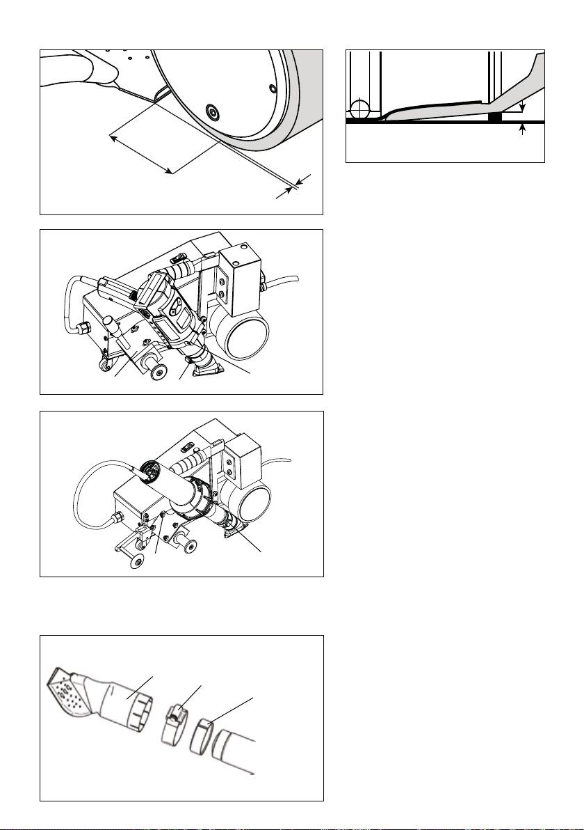
4.3 Overview of the device parts .................................................................................................................7
4.3.1 Overview of the foiler device parts................................................................................................7
4.3.2 Overview of the foiler ETL device parts..........................................................................................8
5. Settings on the foiler / foiler ETL..............................................................................................................8
5.1 Welding nozzle settings.........................................................................................................................9
5.2 Changing the welding nozzle.................................................................................................................9
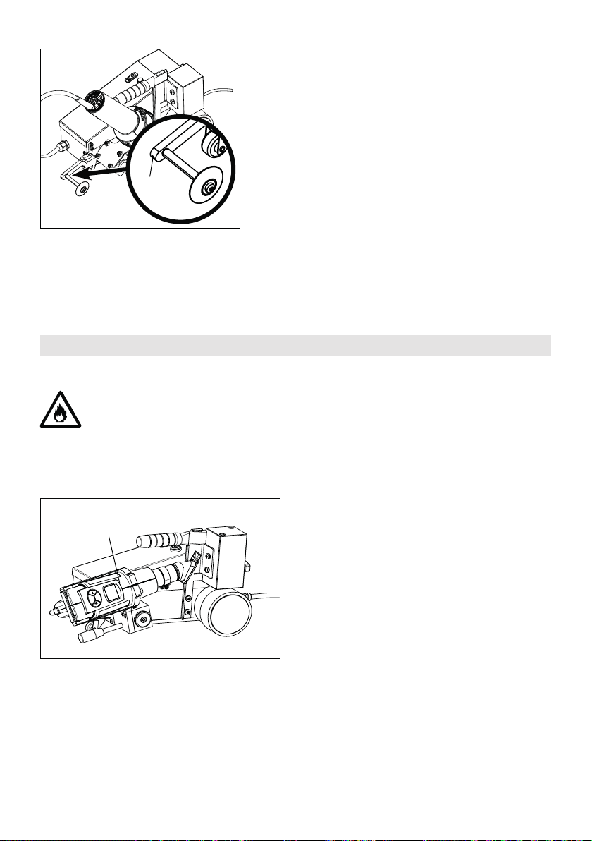
5.3 Setting the track guide roller (foiler ETL only)........................................................................................10
6. Commissioning your foiler......................................................................................................................10
6.1 Working environment and safety..........................................................................................................10
6.2 Operating conditions...........................................................................................................................11
6.3 Switching on ......................................................................................................................................11
6.4 Adjusting the settings on the terminal (10) ...........................................................................................11
6.5 Welding parameters ...........................................................................................................................12
6.6 Tool positioning..................................................................................................................................12
6.7 Welding procedure .............................................................................................................................12
6.8 Switching o......................................................................................................................................12
7. Quick Reference Guide for the foiler ......................................................................................................12
7.1 Switching on / Starting........................................................................................................................12
7.2 Switching o......................................................................................................................................13
8. Commissioning your foiler ETL...............................................................................................................13
8.1 Working environment and safety..........................................................................................................13
8.2 Operating condition ............................................................................................................................13
8.3 Track guide roller (foiler ETL)...............................................................................................................13
8.4 Welding parameters ...........................................................................................................................14
8.5 Tool positioning..................................................................................................................................14
8.6 Welding procedure .............................................................................................................................14
8.7 Switching o......................................................................................................................................14
9. Quick Reference Guide for the foiler ETL................................................................................................14
9.1 Switching on / Starting........................................................................................................................14
9.2 Switching o......................................................................................................................................14
10. Frequently asked questions, causes and measures.............................................................................15
11. Accessories ..........................................................................................................................................15
12. Service and repair ................................................................................................................................15
13. Warranty...............................................................................................................................................15
14. Declaration of conformity.....................................................................................................................15
15. Disposal................................................................................................................................................15

4
You must read these Operating Instructions prior to commissioning the machine. These Operating Instruc-
tions must be kept with the device at all times. If you pass the device on to another person, you must
include the Operating Instructions.
In addition to the safety information in the individual chapters of these Operating Instructions, the following require-
ments must be strictly complied with at all times.
1. Important Safety Notes
Warning
Caution
Danger to life! Before opening the device, disconnect the power plug from the
outlet, because live components and connections are being exposed.
Danger of fire and explosion caused by improper use of the automatic welding
machine (e.g., material overheating), and particularly in the vicinity of flammable
materials and explosive gases.
Risk of burning! Do not touch heating element tube and nozzle when they are
hot. Always allow the device to cool down first.
Do not point the hot air flow at people or animals.
Connect the device to an outlet with a protective conductor. Any interruption of
the protective conductor inside or outside the device is dangerous!
Only use extension cables with protective conductors.
A circuit breaker is urgently required for personnel protection when the device is
used on construction sites.
The nominal voltage indicated on the device must match the nominal voltage
on site. If the line voltage fails, the hot air blower and the drive must be switched
o, move out the hot air blower.
Protect the device against humidity and dampness.
The device must be monitored at all times during operation. Waste heat can
reach flammable materials that are not in view. The device may be used only
by trained specialists or under their supervision. Children are not permitted to
operate the equipment under any circumstances.
FI
Operating Instructions (Original Operating Instructions)
GB
Congratulations on purchasing your foiler / foiler ETL!
You have chosen a first-class automatic hot-air welding machine which has been designed and manufactured in
accordance with the very latest knowledge available in the plastics-processing industry. High-quality materials
have been used in its manufacture.
WELDY foiler / foiler ETL
Welding machine

5
The foiler / foiler ETL is designed for lap welding of tarpaulins and billboards in professional applications.
Only genuine Weldy spare parts and accessories may be used. Failure to use such spare parts and accessories will
invalidate the warranty and guarantee.
Welding processes and types of material
• Overlap welding of thermoplastic sealing sheets (PVC, PP, PE, ECB, EVA, FPO, PIB, PMI, PO, TPO)
• Welding width 20 and 30 mm
Any use other than or beyond that described above is deemed unintended.
2. Technical data
foiler foiler ETL
Nominal voltage V~ 230
Nominal output W 2100 1700
Frequency Hz 50 / 60
Temperature °C 80 – 530 80 – 530
Speed m/min. 1.0 – 7.5
Emission level LpA (dB) 67
Dimensions (L × W × H) mm 445 × 276 × 280
Weight (w/o additional weight) kg 10.8
Mark of conformity
Protection Class I
We reserve the right to make technical changes.
1.1 Intended use
1.2 Non-intended use
The hot-air blower (4) MUST be allowed to cool down prior to transport.
Never use the carrying handle (20) on the device or the transport box for transport with a crane.
3. Transport

6
4
4. Your foiler / foiler ETL
4.1 Type plate and identification
• 1 Device
• Operating instructions
The model and serial number are indicated on your device's type plate. Copy this information into your Operating
Instructions and quote it in all correspondence with our representatives or authorized service points.
Model:.............................................................................................................................................................
Serial number:.................................................................................................................................................
20
Use the carrying handle (20) and the
hot-air blower (4) to lift the automatic
hot-air welding machine by hand.
If assembled (available as an option): Use the
carrying handle of the additional weight with
handle (19) in the center to lift the automatic
hot-air welding machine by hand.
4.2 Scope of delivery
19

7
1. Power supply cord
2. Drive/pressure roller
3. Welding nozzle
4. Hot-air blower
5. Steering roller
6. Positioning lever
7. Housing/chassis
8. Connection cable
9. Air-blower switch
10. Terminal
4.3.1 Overview of the foiler device parts
11. Display
12. SELECT Menu button
13. PLUS button
14. STANDBY/COOL DOWN button
15. MINUS button
16. Drive switch
17. Potentiometer for welding speed
18. Drive roller
19. Additional weight with handle (optional)
20. Carrying handle
1
2
3
4
5
6
7
8
10
11
12
15 13
18
19
20
14
16 17
9
I
0
4.3 Overview of the device parts

8
4.3.2 Overview of the foiler ETL device parts
Allow the device to cool down.
Before commencing the settings, check that the hot-air blower has been switched o at the main
switch (9) and the power supply cord (1) has been disconnected from the line supply.
Safety precautions
5. Settings on the foiler / foiler ETL
1. Power supply cord
2. Drive/pressure roller
3. Welding nozzle
4. Hot-air blower
5. Steering roller
7. Housing/chassis
8. Connection cable
9. Air-blower switch
16. Drive switch
17. Potentiometer for welding speed
18. Drive roller
19. Additional weight with handle (optional)
20. Carrying handle
21. Snap switch (foiler ETL)
22. Track guide roller (foiler ETL)
24. Potentiometer for temperature adjustment
25. Air filter
2
3
4
5
21
22
7
8
24
9
25
18
16
17
20
19 1

9
5.2 Changing the welding nozzle
Change the welding nozzle to the required width as necessary (not included in the scope of delivery).
After changing the welding nozzle, you MUST check the position (as described under Setting the welding nozzle).
5.1 Welding nozzle settings
A= 30 – 40 mm
B= 1 – 2 mm
C= 1 – 2 mm
foiler
The position of the welding nozzle can be
adjusted in the following three places:
• Hexagon socket screws (26)
• Hexagon socket screw (27)
• Screw collar (28)
A
B
C
26 27
28
foiler ETL
The position of the welding nozzle can be
adjusted in the following three places:
• Hexagon socket screws (26)
• Screw collar (28)
1. Unscrew the screw collar (3-2).
2. Remove the current welding nozzle (3-1).
3. Attach the adapter ring (3-3) and the
required welding nozzle (3-1).
4. Tighten the screw collar (3-2) a little.
5. Set the welding nozzle (3-1) (see Setting
the welding nozzle).
6. Screw the screw collar (3-2) tight again.
3-2
3-1
3-3
26 28

10
5.3 Setting the track guide roller (foiler ETL only)
6.1 Working environment and safety
Power supply failure and interruptions to operation
Power supply cable and extension cable
• The nominal voltage indicated on the device (see nameplate) must correspond to the line voltage.
• The power supply cord (1) must be able to move freely and must not hinder the user or third parties while
working (trip hazard).
• Extension cables must be authorized for the utilization site (e.g. outdoors) and be marked accordingly. Observe
the necessary minimum cross-section for extension cables as required.
Power supply equipment
When using power supply equipment, please note that such equipment must be grounded and fitted with a circuit breaker.
The formula “2 x nominal output of the automatic hot-air welding machine” is used to calculate the nominal
output of power supply equipment.
The automatic hot-air welding machine should only be used in the open or in a well-ventilated area.
Never use the automatic hot-air welding machine in a potentially explosive or highly flammable atmo-
sphere and always keep your distance from flammable materials or explosive gases.
Read the material safety data sheet provided by the material manufacturer and follow the instructions
it contains. Be careful not to burn the material during welding.
The device must only be used on a horizontal and fireproof surface.
If the power supply fails, if operation is interrupted or to
cool down the device, swing the hot-air blower (4) into
the parking position.
6. Commissioning your foiler
The track guidance can be adjusted by loosening the hexagon
socket screw (29) and with help from the marking.
4
29

11
6.2 Operating conditions
• Check the welding nozzle (3) basic setting.
• Connect the tool to the line supply. The line voltage must correspond with the voltage rating stated on the tool.
6.3 Switching on
Set the air blower switch (9) to I. Press the SELECT button (12) once.
The heating process starts with the last-saved settings. Select the desired program or program the temperature
and air flow as required.
Language selection Temperature
°C / °F (see 6.4)
or
Selecting the function program
(see 6.4).
Start by pressing the SELECT Menu button (12). Note: When an indication flashes on the display (11), a change
can be initiated by pressing either the PLUS (13) or MINUS (15) button. Press the SELECT button (12) again to
go to the next step.
6.4 Adjusting the settings on the terminal (10)
Language selection, temperature unit °C / °F
Selecting the function program
1. Welding PVC
2. 1-Free setting
3. 2-Free setting
The name of the program corresponding to the selected function program flashes on the display. Longer text scrolls
across the screen after 2 seconds and the name of the program is displayed again after 2 cycles. Within this period,
the SELECT Menu button (12) can be pressed again to adjust the temperature or the air flow.
1 ×
1 ×
1 × 1 ×
1 ×
1 ×
1 ×
2 sec

12
6.6 Tool positioning
6.7 Welding procedure
• Use the positioning lever (6) to turn the hot-air blower (4) up as far as the stop.
• Position the automatic welding machine on the overlap of the material to be welded. The outside edge of the
drive/pressure roller (2) must line up with the overlap edge of the material to be welded.
• Use the positioning lever (6) to turn the hot-air blower (4) down as far as the stop and at the same time turn
on the drive switch (16) (the welding process starts).
• Supervise the welding process. Correct the welding speed with the potentiometer (17) as necessary. Guide the
automatic welding machine by its chassis along the length of the overlap.
• When welding has finished, use the positioning lever (6) to swing up the hot-air blower (4) as far as the stop.
• Switch o the drive switch (16).
6.5 Welding parameters
• Set the potentiometer for the welding speed (17) to the required value.
• Set the air-blower switch (9) to position I. Set the temperature and the air flow to the required values and heat
up for approx. 5 minutes.
• The contact pressure is aected by the weight of the automatic hot-air welding machine itself.
• Use the additional weight accessory as required (optional).
Perform a test weld according to the welding instructions supplied by the material manufacturer and
conforming to national standards or guidelines. Check the test weld. Adapt the welding temperature
(welding parameters) as necessary.
7. Quick Reference Guide for the foiler
7.1 Switching on / Starting
1. Connect the line voltage plug.
2. Switch on the air-blower switch (9) for the hot-air blower (4).
3. Select/set welding program.
4. Set the speed at the potentiometer (17).
5. Swing the hot-air blower (4) and switch on the drive switch (16) at the same time.
6.8 Switching off
To cool down the hot-air blower, press the STANDBY button (14) (COOL DOWN setting). When the unit has cooled
down (after approx. 6 minutes) set the air-blower switch (9) to 0.
Then disconnect the power supply cord (1) from the electricity supply.
• Wait for the device to cool down.
• Check the power supply cord (1) and plug for electrical and/or mechanical damage.
• Clean the welding nozzle (3) with a wire brush.
Selecting STANDBY or COOL DOWN
1 × 1 × 1 ×
• To pause work briefly, press the STANDBY button (14) twice. Power consumption is reduced.
• When you have finished work, always press the STANDBY button (14) to select COOL DOWN.
Switch o the tool according to chapter 6.11 Switching o.

13
7.2 Switching off
1. Swing the hot-air blower (4) up into the parking position and switch o the drive switch (16).
2. Press the STANDBY button (14) on the hot-air blower (4) and allow the device to cool down.
3. Switch o the air-blower switch (9) for the hot-air blower (4).
4. Disconnect the line voltage plug.
8. Commissioning your foiler ETL
The automatic hot-air welding machine should only be used in the open or in a well-ventilated area.
Never use the automatic hot-air welding machine in a potentially explosive or highly flammable atmo-
sphere and always keep your distance from flammable materials or explosive gases.
Read the material safety data sheet provided by the material manufacturer and follow the instructions
it contains. Be careful not to burn the material during welding.
The device must only be used on a horizontal and fireproof surface.
8.1 Working environment and safety
Power supply failure and interruptions to operation
Power supply cable and extension cable
• The nominal voltage indicated on the device (see nameplate) must correspond to the line voltage.
• The power supply cord (1) must be able to move freely and must not hinder the user or third parties while
working (trip hazard).
• Extension cables must be authorized for the utilization site (e.g. outdoors) and be marked accordingly. Observe
the necessary minimum cross-section for extension cables as required.
Power supply equipment
When using power supply equipment, please note that such equipment must be grounded and fitted with a circuit
breaker.
The formula “2 x nominal output of the automatic hot-air welding machine” is used to calculate the nominal
output of power supply equipment.
• Adjust the track guide roller (22) (see Chapter 5.3).
• Check the welding nozzle (3) basic setting.
• Connect the tool to the line supply. The line voltage must correspond with the voltage rating stated on the tool.
8.2 Operating condition
8.3 Track guide roller (foiler ETL)
If the power supply fails, if operation is interrupted, or to
cool down the device, swing the hot-air blower (4) into
the parking position.
4

14
8.5 Tool positioning
8.6 Welding procedure
• Swivel the hot air blower (4) up as far as the stop.
• Position the automatic welding machine on the overlap of the material to be welded. The outside edge of the
drive/pressure roller (2) must line up with the overlap edge of the material to be welded.
• The track guide roller (22) must line up with the overlap edge of the material to be welded.
• Foiler ETL: Swivel the hot-air blower (4) down under as far as the stop; the snap switch (21) automatically
starts the motor drive (the welding process starts).
• Monitor the welding process. If necessary, adjust the welding speed with the potentiometer (17). Guide the
welding machine along the overlap with help from the housing (7) and the track guide roller (22).
• When welding has finished, swing up the hot-air blower (4) as far as the stop.
Perform a test weld according to the welding instructions supplied by the material manufacturer and
conforming to national standards or guidelines. Check the test weld. Adapt the welding temperature
(welding parameters) as necessary.
8.7 Switching off
• Turn the potentiometer (24) to position 0 in order to cool down the hot-air blower (4). When the tool has cooled
down (after approx. 6 minutes), set the hot-air blower switch (9) to 0.
• Then disconnect the power supply cord (1) from the electricity supply.
• Wait for the device to cool down.
• Check the power supply cord (1) and plug for electrical and/or mechanical damage.
• Clean the welding nozzle (3) with a wire brush.
9. Quick Reference Guide for the foiler ETL
9.1 Switching on / Starting
1. Connect the line voltage plug.
2. Switch on the main switch for the hot-air blower (9).
3. Select/set the temperature with the potentiometer (24).
4. Set the speed at the potentiometer (17).
5. Swing the hot-air blower (4).
9.2 Switching off
1. Swing the hot-air blower (4) up into the parking position.
2. Set the potentiometer (24) on the hot-air blower (4) to 0 and allow the device to cool down.
3. Switch o the main switch for the hot-air blower (9).
4. Disconnect the line voltage plug.
8.4 Welding parameters
• Set the potentiometer for the welding speed (17) to the required value.
• Set the air-blower switch (9) to position I. Adjust the temperature as required with the potentiometer (24). The
heat-up period is approx. 5 minutes.
• The contact pressure is aected by the weight of the automatic hot-air welding machine itself.
• Use the additional weight accessory as required (optional).

15
12. Service and repair
Repairs may only be carried out by local Weldy partners. Only genuine accessories and spare parts may be used.
For more information, go to www.weldy.com.
13. Warranty
• The guarantee or warranty rights granted for this device by the direct distribution partner/salesman apply after the
date of purchase.
• In the event of a guarantee or warranty claim (verification by invoice or delivery note), manufacturing or processing
errors will be rectified by the sales partner through replacement delivery or repair.
• Other guarantee or warranty claims are excluded within the framework of mandatory law.
• Damages resulting from natural wear, overload, or improper handling are excluded from the warranty.
• Heating elements shall be excluded from warranty obligations or guarantees.
• No guarantee or warranty claims exist for devices which have been converted or changed by the purchaser or for
which non-original Weldy spare parts have been used.
14. Declaration of conformity
Leister Technologies AG, Galileo-Strasse 10, CH-6056 Kaegiswil, Switzerland confirms that this product
fulfils the requirements of the following EU Guidelines in the models that we have made available for purchase.
Guidelines: 2006/42, 2014/30, 2014/35, 2011/65
Harmonized standards: EN 12100, EN 55014-1, EN 55014-2, EN 61000-6-2, EN 61000-3-2,
EN 61000-3-3, EN 62233, EN 60335-1, EN 60335-2-45, EN 50581
Name of the authorized document official: Volker Pohl, Manager Product Conformity
Kaegiswil, 08/31/2017
Bruno von Wyl, CTO Christoph Baumgartner, GM
15. Disposal
Never dispose of electrical equipment with household refuse!
Electrical equipment, accessories, and packaging should be subjected to environmentally
friendly recycling.
11. Accessories
Only genuine Weldy spare parts and accessories may be used. Failure to use such spare parts and accessories will
invalidate the warranty and guarantee.
For more information, go to www.weldy.com
10. Frequently asked questions, causes and measures
Poor quality welding result:
• Check the drive speed and the welding temperature.
• Clean the welding nozzle (3) with a wire brush.
• Welding nozzle (3) set incorrectly (see Setting the welding nozzle)
The required welding temperature has still not been reached after a maximum of 5 minutes:
• Check the line voltage.

16
TR
Türkçe Çalıştırma Kılavuzu
İçindekiler
1. Önemli Güvenlik Notları..........................................................................................................................17
1.1 Kullanım amacı...................................................................................................................................18
1.2 Amacı dışında kullanım.......................................................................................................................18
2. Teknik veriler ..........................................................................................................................................18
3. Nakliyat...................................................................................................................................................18
4. foiler / foiler ETL .....................................................................................................................................19
4.1 Tip plakası ve kimlik ...........................................................................................................................19
4.2 Teslimat kapsamı................................................................................................................................19
4.3 Cihaz parçalarına genel bakış..............................................................................................................20
4.3.1 foilernin parçalarına genel bakış.................................................................................................20
4.3.2 foiler ETL'nin parçalarına genel bakış..........................................................................................21
5. foiler / foiler ETL üzerindeki ayarlar .......................................................................................................21
5.1 Kaynak nozülü ayarları ........................................................................................................................22
5.2 Kaynak nozülünü değiştirme................................................................................................................22
5.3 Kılavuz rulmanı ayarlama (sadece foiler ETL) ........................................................................................23
6. Folyo makinenizi devreye alma ..............................................................................................................23
6.1 Çalışma ortamı ve güvenlik..................................................................................................................23
6.2 Çalıştırma koşulları .............................................................................................................................24
6.3 Açma.................................................................................................................................................24
6.4 Bağlantı ucundaki ayarların değiştirilmesi (10)......................................................................................24
6.5 Kaynak parametreleri..........................................................................................................................25
6.6 Aletin konumlandırılması.....................................................................................................................25
6.7 Kaynak prosedürü...............................................................................................................................25
6.8 Kapatma............................................................................................................................................25
7. foiler için Hızlı Başvuru Kılavuzu ............................................................................................................25
7.1 Açma / Başlatma................................................................................................................................25
7.2 Kapatma............................................................................................................................................26
8. foiler ETL'yi devreye alma ......................................................................................................................26
8.1 Çalışma ortamı ve güvenlik..................................................................................................................26
8.2 Çalıştırma koşulu................................................................................................................................26
8.3 Kılavuz makaralı (foiler ETL).................................................................................................................26
8.4 Kaynak parametreleri..........................................................................................................................27
8.5 Aletin konumlandırılması.....................................................................................................................27
8.6 Kaynak prosedürü...............................................................................................................................27
8.7 Kapatma............................................................................................................................................27
9. foiler ETL için Hızlı Başvuru Kılavuzu......................................................................................................27
9.1 Açma / Başlatma................................................................................................................................27
9.2 Kapatma............................................................................................................................................27
10. Sık sorulan sorular, nedenler ve önlemler............................................................................................28
11. Aksesuarlar...........................................................................................................................................28
12. Servis ve onarım...................................................................................................................................28
13. Garanti..................................................................................................................................................28
14. Uygunluk beyanı...................................................................................................................................28
15. Elden çıkarma.......................................................................................................................................28

17
Makineyi devreye almadan önce bu Çalıştırma Kılavuzunu okumanız gerekir. Çalıştırma Kılavuzu her
zaman cihazın yanında bulundurulmalıdır. Cihazı bir başkasına devrederseniz, Çalıştırma Kılavuzunu da
birlikte vermeniz gerekir.
Bu Çalıştırma Kılavuzunun ilgili bölümlerindeki güvenlik bilgilerine ek olarak, aşağıdaki gerekliliklere her zaman
harfiyen uyulması gerekir.
1. Önemli Güvenlik Notları
Uyarı
Dikkat
Hayati tehlike! Cihazı açmadan önce, elektrik fişini prizden çıkarın, çünkü elekt-
rikli bileşenler ve bağlantılar açığa çıkarılır.
Yangın ve patlama tehlikesi! Otomatik kaynak makinesinin uygun olmayan şekil-
de kullanılmasından (örn. malzemenin aşırı ısıtılması) ve özellikle yanıcı maddelerin
ve patlayıcı gazların yakınında kullanılmasından kaynaklanır.
Yanma riski! Isıtma elemanının tüpüne ve nozülüne sıcakken dokunmayın. Önce
cihazı soğumaya bırakın.
Sıcak hava akımını insanlara veya hayvanlara doğrultmayın.
Cihazı koruyucu iletkeni olan bir prize bağlayın. Cihazın içindeki ve dışındaki
koruyucu iletkenin kesintiye uğratılması tehlikelidir!
Sadece koruyucu iletkene sahip uzatma kabloları kullanın!
Cihaz şantiyelerde kullanıldığında personelin korunması için bir devre kesici anah-
tar acilen gereklidir.
Cihazda belirtilen nominal gerilim, kullanım yerindeki nominal gerilim ile aynı
olmalıdır. Hat geriliminin kesilmesi durumunda, sıcak hava fanı ve tahrik motoru
kapatılmalıdır, sıcak hava fanı dışarı çıkarılmalıdır.
Cihazı nem ve rutubetten koruyun.
Cihaz çalışma sırasında her zaman izlenmelidir. Artık ısı, görüş alanında ol-
mayan yanıcı malzemelere ulaşabilir. Cihaz yalnızca eğitimli uzmanlar tarafından
veya bu kişilerin gözetiminde kullanılabilir. Çocukların herhangi bir koşul altında
cihazı kullanması kesinlikle yasaktır.
FI
Çalıştırma Kılavuzu (Orijinal Çalıştırma Kılavuzu'nun çevirisi)
TR
foiler / foiler ETL aldığınız için tebrikler!
Plastik işlem endüstrisindeki mevcut en yeni bilgiler doğrultusunda tasarlanıp üretilen, birinci sınıf otomatik bir
sıcak hava kaynak makinesini tercih ettiniz. Makinenin üretiminde yüksek kaliteli malzemeler kullanılmıştır.
WELDY foiler / foiler ETL
Kaynak makinesi

18
foiler / foiler ETL, profesyonel uygulamalarda branda ve ilan panolarının bindirmeli kaynaklaması için tasarlanmıştır.
Yalnızca orijinal Weldy yedek parçaları ve aksesuarları kullanılabilir. Orijinal yedek parça ve aksesuarların kullanıl-
maması garantiyi geçersiz kılar.
Kaynaklama işlemleri ve malzeme tipleri
• Termoplastik mühürleme brandalarının bindirmeli kaynağı (PVC, PP, PE, ECB, EVA, FPO, PIB, PMI, PO, TPO)
• Kaynaklama genişliği 20 ve 30 mm
Yukarıdaki açıklamaların dışındaki veya ötesindeki tüm kullanımlar, amaç dışı olarak nitelendirilir.
2. Teknik veriler
foiler foiler ETL
Nominal gerilim V~ 230
Nominal çıkış G 2.100 1.700
Frekans Hz 50 / 60
Sıcaklık °C 80 – 530 80 – 530
Hız m/dk. 1,0 – 7,5
Emisyon seviyesi LpA (dB) 67
Boyutlar (U × G × Y) mm 445 × 276 × 280
Ağırlık (ek ağırlık olmadan) kg 10,8
Uygunluk işareti
Koruma Sınıfı I
Teknik değişiklikler yapma hakkımız saklıdır.
1.1 Kullanım amacı
1.2 Amacı dışında kullanım
Sıcak hava üfleyici (4) taşınmadan önce soğumaya BIRAKILMALIDIR.
Nakliyat kutusundaki veya cihaz üzerindeki taşıma kolunu (20) kesinlikle vinçle nakliyat
için kullanmayın.
3. Nakliyat

19
4
4. foiler / foiler ETL
4.1 Tip plakası ve kimlik
• 1 Cihaz
• Çalıştırma kılavuzu
Model ve seri numarası cihazınızın tip plakasında belirtilmiştir. Bu bilgiyi Çalıştırma Kılavuzunuza kopyalayın ve
temsilcilerimiz veya yetkili servis noktalarıyla yapacağınız tüm yazışmalarda belirtin.
Model:.............................................................................................................................................................
Seri numarası: .................................................................................................................................................
20
Otomatik sıcak havalı kaynak makinesini elle
kaldırmak için taşıma kolunu (20) ve sıcak
hava üfleyiciyi (4) kullanın.
Monte edilmişse (opsiyon olarak temin edilir):
Otomatik sıcak havalı kaynak makinesini
elle kaldırmak için ortada kolu (19) olan ek
ağırlığın taşıma kolunu kullanın.
4.2 Teslimat kapsamı
19

20
1. Güç kaynağı kablosu
2. Tahrik/basınç silindiri
3. Kaynak nozülü
4. Sıcak hava üfleyici
5. Yönlendirme silindiri
6. Konumlandırma levyesi
7. Muhafaza/sasi
8. Bağlantı kablosu
9. Hava üfleyici şalteri
10. Bağlantı ucu
4.3.1 foilernin parçalarına genel bakış
11. Ekran
12. SELECT Menu (SEÇ Menü) düğmesi
13. ARTI düğmesi
14. STANDBY/COOL DOWN (BEKLEME/SOĞUMA) düğmesi
15. EKSİ düğmesi
16. Tahrik şalteri
17. Kaynaklama hızı için potansiyometre
18. Tahrik silindiri
19. Kollu ek ağırlık (opsiyonel)
20. Taşıma kolu
1
2
3
4
5
6
7
8
10
11
12
15 13
18
19
20
14
16 17
9
I
0
4.3 Cihaz parçalarına genel bakış
This manual suits for next models
1
Table of contents
Languages:
Other WELDY Welding System manuals

WELDY
WELDY miniwelder tex2 User manual

WELDY
WELDY booster EX2 User manual

WELDY
WELDY roofer RW3400 User manual

WELDY
WELDY booster EX2 User manual

WELDY
WELDY booster EX2 User manual

WELDY
WELDY sealer GW800 User manual

WELDY
WELDY Energy HT1600 User manual

WELDY
WELDY WGW 300 User manual

WELDY
WELDY miniwelder tex1 User manual

WELDY
WELDY miniwelder geo2 User manual