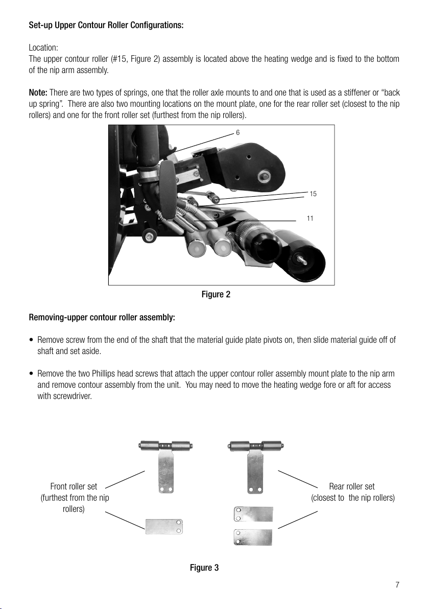
manuals.online logo
Brands
  1. Home
  2. •
  3. Brands
  4. •
  5. WELDY
  6. •
  7. Welding System
  8. •
  9. WELDY WGW 300 User manual

WELDY WGW 300 User manual

1
CN
GB
WGW 300
莱丹塑料焊接技术(上海)有限公司
地址:上海莘庄工业园区元科路155号11幢厂房邮 编 :2 0 1 1 0 9
热 线 电 话 :4 0 0 0076695网址:www.leisterchina.com
2
GB
CN
English Operating Instructions 3
中文 操作手册 13
3
GB
Operating instructions (Translation of the original operating instructions)
Warning
Caution
Please read operating instructions carefully before use
and keep for further reference.
WGW 300
Danger to life: is electrocution risk due to exposure to live components
and connections. Unplug the device from the outlet before opening.. Prior
to operating, check the power cord, the plug, and the extension cable for
electrical and mechanical damage.
Danger of fire and explosion: If the device is used improperly, there is a risk
of fire and/or explosion (e.g., due to the material overheating), particularly in
the vicinity of flammable materials and explosive gases.
Risk of burning: Do not touch heating element tube and/or nozzle/hot wedge
when they are hot. Allow the device to cool down first. Never point the hot air
flow at people or animals.
Connect the device to a socket with a protective conductor. Any interruption
of the protective conductor inside or outside of the device is dangerous. Only
use extension cables with protective conductors.
The nominal voltage specified on the device must match the local supply
voltage. If the line voltage fails, then the main switch and the drive must be
switched off.
If the device is being used on job sites, a GFI protective switch must be used
to protect site personnel.
The device must be supervised at all times during operation. Excess heat
can come into contact with flammable materials that are in proximity of tool.
Device may be operated only by or under their supervision. Children are not
permitted to operate the device under any circumstances.
Protect the device from moisture and wet conditions.
4
General Safety Information
The WGW 300 is a high voltage piece of equipment. Always disconnect the power source before performing
service and maintenance to the unit. Never pull or carry welder by the power cord or electrical connection.
Always keep slack in extension cord while in operation to avoid damage to the power connection. Keep hands
and other body parts clear of heating wedge and elements when hot. Do not operate near flammable materials.
Do not apply flammable liquids to seam area. Allow unit to cool down for at least 5 minutes before putting back
into shipping/storage case. Protect unit from exposure to direct rainfall or standing water. Never attempt to weld
in standing water.
Intended Use
For additional product information please refer to the product data sheet. The WGW 300 has been manufactured
according to the latest technology and current safety regulations. However, improper use or abuse may lead to
hazardous conditions for the user or third party or damage to the unit.
Always have this manual handy at the location where the WGW 300 is being used so that it can be referred to
quickly and easily.
The technician assigned to operate this welder must have read through and become familiar with this manual
before starting work, particularly the section on safety.
Do not make changes or modifications to the WGW 300 relative to safety without contacting the manufacturer for
advice.
Maintenance
Maintenance, inspection and adjustment of the WGW 300 may only be carried out by qualified personnel.
Before removing or installing spare parts or performing other repair operations to the WGW 300, consult the
manufacturer for advice on proper procedures. This will help insure a safe and successful outcome. Always make
sure all screw connections are tight before attempting to operate the unit after maintenance or repair. Also make
sure all covers, guards, and other safety devices have been reinstalled before use.
Power Requirements
The voltage requirement of your WGW 300 hot wedge welder depends on voltage specified when ordered. WGW
300 will operate properly at 208VAC to 240VAC.
Note: The above operating voltage ranges refer to actual voltage at point of welder plug-in. In other words, the
voltage under load at the welder end of the extension cord. To measure voltage under load, connect the welder
to the extension cord and generator that will be used. Start the generator and turn both welder power switches to
the on position. While the number 1 indicator light on the temperature controller is illuminated and the wedge is
heating, separate the plug at the end of the welders power cord just enough to expose the prongs. Using a digital
voltmeter, measure the voltage under load between the hot and neutral prongs.
This procedure should only be performed by a qualified electrician.
Generator Recommendation
If using house power from a building circuit, please contact the manufacturer for advice on plug and cord
5
configuration. In-field generators should be rated for at least 3500 watts; however, a rating of 5000 watts or more
is recommended in order to obtain the best welder performance and temperature control. As a rule, the higher
the wattage of the generator, the better the performance of the welder. Keep in mind that the length and wire
gauge of the extension cord being used, combined with the capacity of the generator, will ultimately determine the
operating voltage reaching the welder.
Extension Cords
Extension cords should be at least 3 x 1.5m2 with ground connections.
Technical Data WGW 300
Voltage V~ 230V
PowerW
1750W
Dimension mm 445 x 323 x 315
Weight kg 15
TemperatureOC~450
Speed m/min
0 ~ 8.5
Weldable materials HD-PE, LD-PE, PP, PE
Technical data and specifications are subject to change without prior notice
Material Set-up
The WGW 300 is designed to weld a wide range of material types and thickness from very thin PE and PP to very
thick materials such as 1.5-2.5mm HDPE. The WGW 300 uses a spring-loaded upper contour roller system and
“floating” wedge design that allows the operator to weld several different thicknesses of material without resetting
the adjustments. However, for best results on all materials, the following set-up procedure can be used.
Important! Unit must be cooled down before attempting adjustments.
Please refer to the parts identification photos as instructed throughout the set up procedure.
Figure 1
6
14
6
Set-up Nip Pressure Adjustment:
Adjustment Location:
The nip pressure adjustment is located between the nip lever and upper nip arm; it is a hex shaped turnbuckle
style nut (#6, Figure 1).
The correct amount of nip pressure is needed to get a good weld. It is also important that the nip rollers are
providing enough traction to keep the WGW 300 from “burning out”. This can happen when the nip rollers lose
traction and spin on the material, causing the WGW 300 to stop in the seam and burn a hole in the material.
Note: Pressure Adjustment for thin material and geotextiles:
These materials require less nip pressure. Too much pressure can cause the material to perforate at the edge of
the seam causing a “zipper” effect.
• Make sure the heating wedge (#14, Figure 1) is in the disengaged position.
• Turn the nip pressure adjustment hex nut clockwise while looking down from above several turns, raising the
nip arm up to give a fresh starting point for this adjustment. (Loosen set screw(s) on hex nut first if present to
avoid damaging threads on eye bolts)
• Place one end (one thickness) of your adjustment material between the nip rollers and into the unit about 1”
inch. Engage nip rollers by pushing down on the nip lever until it has “clicked” into place and is held in position
by the lock pin. At this point the material should move around freely between the nip rollers.
• Turn the hex nut (#6, Figure 1) counter clockwise until the nip rollers begin to pinch down on the material and
you cannot turn the nut by hand anymore. This zeroes the adjustment.
• Disengage nip rollers and turn the hex nut counter clockwise one full rotation.
• Insert the adjustment material (the opposite end of the fold, two thicknesses) between the nip rollers and
engage nip rollers together until the lock pin clicks into its detent as shown on the Figure 1. Check pressure
by attempting to move the material side to side. If you are able to move the material or pull the material
straight out without the nip rollers turning, disengage the nip pressure and turn adjustment nut (#6, Figure 1)
counter clockwise ¼ turn at a time until the desired pressure is reached. Remember to tighten the set screw(s)
on the adjustment nut after you have completed adjustment of the nip pressure to prevent the pressure from
backing off while welding.
Note: When the nip pressure adjustment is set correctly, engaging the nip pressure lever should take some effort
but it should feel like a smooth motion. Again, it is important that you are getting enough traction to avoid burning
out and at the same time providing enough nip pressure to create a good weld. Keep in mind that the thicker the
material being welded and especially textured material, the greater the pressure should be.
7
Set-up Upper Contour Roller Configurations:
Location:
The upper contour roller (#15, Figure 2) assembly is located above the heating wedge and is fixed to the bottom
of the nip arm assembly.
Note: There are two types of springs, one that the roller axle mounts to and one that is used as a stiffener or “back
up spring”. There are also two mounting locations on the mount plate, one for the rear roller set (closest to the nip
rollers) and one for the front roller set (furthest from the nip rollers).
Removing-upper contour roller assembly:
• Remove screw from the end of the shaft that the material guide plate pivots on, then slide material guide off of
shaft and set aside.
• Remove the two Phillips head screws that attach the upper contour roller assembly mount plate to the nip arm
and remove contour assembly from the unit. You may need to move the heating wedge fore or aft for access
with screwdriver.
Figure 2
Front roller set
(furthest from the nip
rollers)
Rear roller set
(closest to the nip rollers)
Figure 3
6
11
15
8
12 13
• With the nip pressure lever in the up position and the wedge in the disengaged position, insert the adjustment
material that you cut earlier from the template into the WGW 300 as shown in Figure 4 above:
• Insert just enough in so that about 70mm of material is protruding out of the nip rollers from the point where
the nip rollers pinch down on the material. Slide the wedge to its engaged position until it locks into its detent.
Then lock the nip pressure lever down on to the material.
• With a Phillips screw driver remove lower frame chain cover (#7, Figure 7) to expose the lockdown bolt for the
front lower contour roller.
Note 1:
• Please pull out rubber plugs before adjusting the both rollers (#12 and #13 in Figure 4) and insert them back to
original position after adjustment finished.
• Using a 6mm Allen wrench, loosen the lockdown bolt and then temporarily adjust the front lower contour roller
down, clockwise, away from the wedge using a 4mm Allen wrench on the end of the roller (this will give you a
fresh starting point and you will make a final adjustment on this roller later).
• Using a 13mm open end wrench, loosen the lockdown bolt (hex head) for the rear lower contour roller (#13,
Figure 4). You can now adjust the height of the wedge by adjusting the rear lower contour roller up or
down with a 4mm Allen wrench at the end of the roller. Once the desired position has been achieved, tighten
the lockdown bolt (hex head) then check the adjustment again to make sure it did not move when tightened.
• The most important adjustment is the positioning of the wedge in relationship to the lower nip roller (#17,
Figure 4). The distance between the lower tip of the heating wedge and the lower nip roller should be
slightly more than the thickness of the material you will be welding. The distance is set by adjusting
the rear lower contour roller (#13, Figure 4) up or down.
Set-up Lower Contour Roller Adjustment
Location:
The lower contour rollers (#12, #13, Figure 4) are located below the heating wedge and are mounted to the lower
frame directly in front of the lower nip roller. For this adjustment you will need a 13mm open end wrench and a
4mm and 6mm Allen wrench.
Figure 4
17
9
Note 2: When adjusting the lower contour rollers (#12) and (#13) rotate them both to the right (counterclockwise)
and up so that in their adjusted positions the rollers are closest to the nip roller (#17). Also because the rear
contour roller (#13) is forcing the wedge up against the upper contour roller spring tension, you may notice the
roller will still spin with your fingers. This is normal. The amount of resistance of the roller when turning it with
your fingers does not matter.
Warning! If the rear lower contour roller is adjusted too high, there will not be enough clearance for the top sheet
to travel through the welder and it will be pinched between the top of the heating wedge and the upper nip frame.
This will result in loss of welding nip pressure and an inconsistent weld.
• Figure 4 until it just comes in contact with the material. The roller should have a slight amount of resistance as
you rotate it. If you adjust it to tight it will rock the wedge and change the rear roller (#13) adjustment.
Note 3: If you are setting up the WGW 300 to weld thin material or in very hot ambient conditions the front
contour roller (#12) adjustment should be set very loose or backed off completely to reduce material dwell time (over
heating material) and minimize the possibility of burn outs.
• Step 4: Set-up Wedge Fore/Aft Adjustment
The fore/aft adjustment sets the limit of travel of the heating wedge in its fully engaged position. In other
words, how close the tip of the wedge is to the nip rollers. If the tip of the wedge is too close to the nip rollers
they will pinch down on the wedge when pressure is engaged, reducing the amount of nip pressure on the
heated material. This can also cause damage to the tip of the wedge when running out of the end of the seam.
Adjustment procedures for lock mount assemblies (Figure 5):
• With the material set-up piece in place and with the nip lever and wedge engaged as shown on Figure 5, use
a 5mm Allen wrench to loosen the wedge mount bolt that connects the wedge hex mount to the wedge slide
lock mount (#18, Figure 5).
• Using a 3mm Allen wrench, loosen the two lock screws that hold the lower piece of the assembly to the upper
piece. You will need to insert the 3mm Allen wrench between the cartridge heater lead wires to access one of
the screws.
• Move the heating wedge forward or backward (left or right) so that there is plenty of clearance between the
tip of the wedge and the upper and lower nip rollers. When adjusting WGW 300 for welding HDPE the
tip of the wedge should have the same clearance as shown in Figure 4.
• Tighten lock screws to set adjustment. Re-check all adjustments to make sure they are correct before
disengaging nip lever and wedge and removing material set-up piece.
Figure 5
18
10
Power Up
Connect the WGW 300 power cord to power source making sure that the voltage is correct for the model of
welder you have.
Flip the main power toggle switch (#1, Figure 6) to the “on” position (up). The main power switch is located on
the right of the control box, below the front handle. After a 3 second delay, the temperature control unit (#5,
Figure 6) located on top of the control box should light up and display current wedge temperature.
Turn on the drive motor with the motor switch (#3, Figure 6), located on the top of the control box. It is
recommended that the drive motor remain on at all times while the welder is plugged in. This helps to eliminate
hot spots on the nip rollers and makes starting a weld quicker and easier.
Setting Wedge Temperature
• OMRON Controller (5 button style)
Temperature controller has a dual display. The current wedge temperature set point is displayed on the right side
of the display. The actual wedge temperature is displayed on the left side of the display.
To adjust the wedge temperature set point, press the up arrow button to increase the set point or the down arrow
button to decrease the set point. Flip the heating switch (#4, Figure 6) to the "on" position, heating start to work
immediately.
Setting Weld Speed
To set weld speed, use the knob directly (#3, Figure 6) located on top of control box, next to temperature control
unit. Please refer the chart on the top of control box to get the correct speed value.
Welding Procedure
Figure 6
5
4
2
3
1
11
Starting a Weld
To start a weld, you must first make sure that the material to be welded is set at the proper overlap. The optimum
overlap is 12.7-15.2cm for field welds.
Start the loading process with the nip lever in the “up” or disengaged position, the heating wedge in the
“forward” or disengaged position (Figure 8), and the motor on with the nip rollers turning.
First, peel back the top sheet to expose the bottom sheet. Load bottom sheet of the material into welder, between
both lower contour rollers and the bottom of heating wedge, then between the two nip rollers.
Second, insert the top sheet into the welder, between the upper contour roller(s) and the top of the heating wedge,
and then between the nip rollers. You may need to roll the welder forward and backward a little for both sheets to
settle into the welder.
Third, pull out on the wedge lock handle and slide wedge toward nip rollers until the lock pin slides off the end on
the slide rail. Make sure wedge is completely engaged before continuing.
Fourth, engage nip rollers by pushing the nip pressure lever down until it “clicks” and is locked in position. At
this time the welder should be moving and welding on its own. If the nip rollers are spinning on the material
and burning a hole, quickly disengage nip rollers, roll the welder down the seam a few more inches, past the
overheated area, and engage again.
Ending a Weld
Just as the welder is about to run out of the end of the seam, disengage nip rollers, slide welder out of the seam,
and then disengage wedge. At this time it is a good idea to tip the WGW 300 up onto the front handle, raising the
back of the unit, to prevent a hole being melted in the material from heat radiating from the wedge.
Shut-Down
To shut down the WGW 300, simply turn main switch to the “off” position or unplug unit. After 5-10 minutes,
place unit in shipping/storage case provided with welder.
12
WGW300Diagram
1 Main Switch 2 Drive Motor Switch 3 Knob Speed Setting
4 Heating Switch 5 Temperature Control Unit 6 Pressure Adjustment Hex Nuf
7 Lower Frane Chain Cover 8 Front Handle 9 Heating Wedge Slide Handle
10 Lock Handle 11 Heating Cartridge 12 Front Lower Contour Roller
13 Rear Lower Contour Roller 14 Heating Wedge 15 Upper Contour Roller
16 Upper Nip Roller 17 Lower Nip Roller 18 Lock Mount
13
12
11
1
10
9
16
15
14
18
17
6
83
2
4
5
7
Figure 8
Figure 7
13
操作手册(基于原文件的翻译)
警告
注意
请在使用设备前仔细阅读操作手册,
并妥善保管以备今后查阅。
WELDY WGW 300
触电风险!
请按照手册操作,在打开机盖,接触外露的电气元件或接头前,
断开设备电源。
火灾风险!
设备会产生高温,在施工和放置设备时,远离可燃物和易爆气体。
烫伤风险!
在设备加热时,切勿接触设备的加热单元和热锲。
为了避免触电,必须依照国家或当地的法规,将设备接地。
使用的电源电压必须和设备的额定电压一致,避免损毁设备。
为了操作人员的人身安全,我们强烈建议将设备连接在带漏电
保护装置的供电设备上。
设备必须处于人员的监控下进行操作,禁止儿童和其他不合规
人员操作设备。
请勿在雨天操作设备,设备的存放保管应注意防水防潮。
CN
14
通用安全说明
WGW 300 是高电压设备,在维护保养设备时必须断开电源。禁止用设备的电源线拖拽焊接机。
焊接时,要保持电源线不受力,避免扯断电线。避免手部或人体其它部位接触热的焊锲。
禁止在易燃物附近操作设备。
在把设备装回包装箱,至少让设备冷却 5 分钟。避免设备暴露在雨水中,并禁止在水中使用
焊接机。
正确使用
更多的产品信息,请见技术参数。
WGW 300 采用最先进的技术生产并符合当代的法规。但是,使用不当会威胁操作者和他人
的人身安全,或者损坏焊接机。
请保管好手册,以便在使用焊接机时快速查阅。
被任命的操作员在工作前,必须通读并熟悉此手册。
为了安全考虑,请不要擅自改装 WGW 300 焊接机。
保养和维修
维护保养须由专人进行,在拆装焊接机前请咨询焊接机生产厂商。维护后,请确保所有的螺
丝安装紧密,安装所有的护罩和机盖。
设备只能由莱丹授权的服务中心维修。服务中心会在 24 小时内提供正确可靠的维修服务,
使用正品备件, 按照电路图和备品表维修。
电源要求
额定电压为 220V 的 WGW 300 焊接机可在 208~240V 间正常工作。
注意:以上的电压范围指焊接机的实际接进电压,或者是电源延长线焊接机端的电压。测量
电压的方法:把焊接机连接延长线和发电机,启动焊接机,打开加热和驱动开关。焊接机温
度指示灯亮,正常加热时,略微拔出焊接机插头,露出电线的插座接头。使用电压表测量插
座接头的电压。
必须由专业人员来测量电压!
发电机的推荐规格
如果将市电接入焊接机,请联系厂家提供电线和插头的规格建议。现场的发电机必须保持
3500W 以上的功率。推荐使用 5000W 或更高功率的发电机,发挥焊接机的最佳性能,实现
更好的温度控制。发电机的功率越高,焊接机的性能越稳定。请注意电线的长度和尺寸,电
线和发电机的配合将决定焊接机的工作电压。
电线
无论长度多少,推荐选用截面积为 3x1.5mm2的带接地线。
15
技术参数WGW 300
电压
 V~ 230V
功率W
1750W
尺寸 mm 445 x 323 x 315
重量
 kg 15
温度
OC~450
速度
 m/min
0 ~ 8.5
焊接材料
HD-PE, LD-PE, PP, PE
更改技术数据和规格恕不另行通知。
按照材料的厚度设定焊接机
WGW 300 采用弹片式上导向轮和“悬浮式”热锲,可用于焊接 1.5~2.5mm 的 HDPE 膜材。
重要!必须在冷却状态下进行调整。
请按照以下步骤进行设定:
压力设定:
调整位置:压力调整零件是位于压力杆和上压力臂之间的压力调节螺柱(6)
需要设定正确的压力,达到高质量的焊接效果。同时,压力轮提供足够的牵引力也是很重要的,
这能避免焊接机烧穿膜材。当压力轮失去牵引力而在膜材上空转时,会发生这种情况。此时
的焊接机会停留在原地,烧穿焊接机下面的膜材。
注意:焊接薄材料的压力调节
此类材料需要较小的压力。压力过大会因为剪切效应而造成材料从焊缝边缘破裂。
6
14
16
• 确认焊锲(14)在待机位置。否则,用手柄把焊锲回拉,后退到待机位置。
• 顺时针方向转动压力调节螺柱(6)数圈,抬起压力臂准备开始调节。(先把螺柱上方的
锁定螺丝松开,避免损毁球头螺丝的螺纹。)
• 取一段待焊接的材料,把一端(一层材料)放入压力轮之间,约 3cm。按住压力杆下压
到正确的位置,扣入锁定销定位。此时,材料可以不受阻力的在压力轮中间移动。
• 逆时针转动螺柱(6),直到压力轮下压接触到材料并且无法再用手转动为止。
这是调节压力的归零步骤。
• 抬起压力臂,脱开压力轮。再按照逆时针转动一整圈。
• 再次在压力轮之间放入待焊接的材料(把材料对折再放入,两层材料厚度),直到
锁定销弹入孔位。拖动膜材,确认压力是否足够。如果能够拖动材料,或者直接把材
料从压力轮中抽出,则需要松开压力轮,把螺柱再沿逆时针方向转动四分之一圈。在设定
好压力之后,记得把锁定螺丝拧紧,防止在焊接时压力轮被顶开而失去压力。
注意:正确地设定压力后,按下压力杆会有些费力但是仍有顺滑的感觉。重申,足够的牵引
力非常必要,以避免烧毁材料。请谨记:材料越厚,尤其是糙面膜材,压力应当越大。
上导轮位置:上膜材导轮(15)位于热锲上方,安装于压力臂的底部。改变弹片的数量,会
改变导轮的松紧度。
注意:WGW 300 出厂配置如下图,适用于 1.5-2.5mm 的 HDPE 膜材焊接。除非需要更换上
导轮,请忽略以下步骤。
设置上膜材导轮:
6
14
15
17
位置:下膜材导轮(12) (13) 位于热锲下方,直接安装在支架上。
需要使用 4mm 内六角扳手,6mm 内六角扳手和 13mm 开口扳手来调节。
• 抬起压力臂,如图放入待焊接的材料。
• 把材料对折后塞入焊接机,放于热锲的上下两端。放入足够的长度(约 7cm):确保把
热 锲向前推送到焊接位置,并把压力轮下压后,膜材完全接触到 2 个下导轮。
• 取下螺丝,移除下链条护盖 (7),露出前侧下导轮 (12) 的固定螺丝。
• 使用内六角扳手松开固定螺丝,把下导轮向下转动,远离压力轮。( 后设定到最佳位
置后再固定)
• 用 13mm 开口扳手松开后侧下导轮(13)的固定螺丝。松开后,可以通过抬高或降
低后侧下导轮来调整热锲的高度。当达到合适的位置时,把固定螺丝锁紧。按下压力臂,
确认螺丝没有松动。
设定下膜材导轮:
把挡板固定轴上的螺丝松开,取下挡板。
松开固定上膜材导轮于压力臂上的 2 颗螺丝,把导轮从焊接机上取下。过程中,需要前后调
整热锲的位置。
拆卸上膜材导轮:
前侧上导轮
(远离压力轮)
后侧上导轮
(靠近压力轮)
12 13
18
• 把前侧下导轮(12)向右上方调整(逆时针方向),直到和膜材接触。此时,转动导轮时
略有阻力。如果拧太紧,前侧下导轮会挡住热锲并改变后侧下导轮的设定位置。
注意:
调整导轮 12 和 13 时请先拔出白色硅胶堵头,调整完毕后再塞回原位置。
最重要的是,热锲和压力轮(16)的相对位置。热锲的尖端和压力轮的距离要比膜材的厚度
略大。通过调整后侧下导轮(13)的上下来调整距离。
当把下导轮(12) (13)同时按逆时针方向转动时,调节下导轮的高度。此时的下
导轮会非常靠近下压轮(16)。又因为后侧下压轮把热锲挺起到上压轮弹片,你会发现能够
转动下压轮。这是正常现象,而转动的阻力大小无关紧要。
警告!如果后侧下导轮 (13) 的位置设定过高,会导致热锲上方的间隙不足,上层膜材被夹住
无法穿过焊接机。这会导致焊接压力下降,焊接不稳定。
如果焊接薄材料,或者高温下作业时,前侧下导轮应该设定得更加松甚至脱离材料。这样可
以减少材料的接触时间(防止材料过热)尽可能避免烧穿材料。
设定热锲的前后位置:
设定热锲在焊接位置时,压力臂下压后的行程限制位置。松开锁定座(18)的螺丝,把热楔
调整到合适位置后重新锁定。换言之,设定热锲尖端和压力轮之间的距离。如果尖端太靠近
压力轮,下压时压力轮会夹住热锲尖端,造成焊接压力下降。另外,焊接结束后,焊接机自
动从膜材中驶出,压轮会把热锲压坏。
18
19
先确认电压、电线规格和长度,再接通焊接机电源。
打开电源开关(1),约 3 秒后,温控仪(5)显示出当前的热锲温度。
打开马达开关(2),推荐在焊接机开机时,马达始终在启动状态。这样做,能避免
压力轮的某一个位置过热,在开始焊接时更加顺畅。
设定热锲温度:
WGW 300 装配的温度控制器在出厂前经过调试。在开机后,通过温控仪的“上︿”和“ 下 ﹀”
按键设定温度。温度控制器能显示设定值和实际值。设定所需的温度后,打开温度开关 (4),
焊接机开始迅速加热。
设定焊接速度:
使用旋钮直接调节速度。请参考在面板正面的速度值对照表,获得合适的速度。
开始焊接
开始焊接前,必须把膜材放入合适的交叠位置。工地现场理想的交叠宽度是 12~15cm。
开始焊接前,压力臂抬起,处于张开状态;热锲处于待机位置;马达打开,压力轮
持续转动。
首先,拨开上层的膜材,露出下层的材料。把下层材料放入焊接机,放在下导轮和热锲底部
之间,并且向前达到压力轮。
焊接过程
5
4
2
3
1
20
然后,把上层材料放入焊接机,放在上导轮和热锲顶部之间,并且向前达到压力轮。需要前
后挪动焊接机,把两层材料放置到位。
第三步,拔出热锲的定位手柄,把热锲滑向压力轮的方向,直到定位手柄在滑轨另一端弹入
定位槽。确认热锲已经固定后,继续下一步。
最后, 把压力臂按下,直到定位销弹入凹槽,压力锁定。此时,焊接机开始自动行走并焊接。
如果压力轮夹住材料,把材料烧穿,请迅速打开压力臂把焊接机向后拖动约 10cm,离开过
热的区域重新按下压力臂,开始焊接。
焊接结束
在焊接机快要从膜材末端驶出时抬起压力臂,把焊接机从焊缝处拖出,再把热锲退回到待机
位置。向上提起前把手,把机器略微抬高,能有效避免热锲把材料熔融。
关机
直接关掉电源主开关 ( 如图 ) 或拔掉电源线插头 ( 仅在紧急情况 )。约 5~10 分钟后,再把设
备放入包装箱。
21
WGW300示意图
1 电源开关 2 驱动开关 3 速度旋钮
4 加热开关 5 温控仪 6 压力调节螺柱
7 链条盖 8 手柄 9 焊锲滑动手柄
10 锁定手柄 11 加热棒 12 前侧下膜材导轮
13 后侧下膜材导轮 14 热锲 15 上膜材导轮
16 上驱动轮 17 下驱动轮 18 固定座
13
12
11
1
10
9
16
15
14
18
17
6
83
2
4
5
7

Other WELDY Welding System manuals

WELDY sealer GW800 User manual

WELDY

WELDY sealer GW800 User manual

WELDY miniwelder geo2 User manual

WELDY

WELDY miniwelder geo2 User manual

WELDY booster EX2 User manual

WELDY

WELDY booster EX2 User manual

WELDY miniwelder tex2 User manual

WELDY

WELDY miniwelder tex2 User manual

WELDY booster EX2 User manual

WELDY

WELDY booster EX2 User manual

WELDY Energy HT1600 User manual

WELDY

WELDY Energy HT1600 User manual

WELDY miniwelder geo2 User manual

WELDY

WELDY miniwelder geo2 User manual

WELDY roofer RW3400 User manual

WELDY

WELDY roofer RW3400 User manual

WELDY booster EX2 User manual

WELDY

WELDY booster EX2 User manual

WELDY foiler User manual

WELDY

WELDY foiler User manual

WELDY miniwelder tex1 User manual

WELDY

WELDY miniwelder tex1 User manual

Popular Welding System manuals by other brands

Lincoln Electric Pro-MIG 140 Operator's manual

Lincoln Electric

Lincoln Electric Pro-MIG 140 Operator's manual

Miller Electric STH 160 owner's manual

Miller Electric

Miller Electric STH 160 owner's manual

Electrex TS 210 AC user manual

Electrex

Electrex TS 210 AC user manual

Migatronic MULTIMOTIVE Duo instruction manual

Migatronic

Migatronic MULTIMOTIVE Duo instruction manual

stayer PLASMA25GE operating instructions

stayer

stayer PLASMA25GE operating instructions

Miller Electric Voltage Interface Control owner's manual

Miller Electric

Miller Electric Voltage Interface Control owner's manual

ESAB PT-31XL instruction manual

ESAB

ESAB PT-31XL instruction manual

Kemppi MLS 2300 ACDC operating manual

Kemppi

Kemppi MLS 2300 ACDC operating manual

widos ASM 160 Working Instructions Translation

widos

widos ASM 160 Working Instructions Translation

ims PRO ARCPULL 350 user manual

ims PRO

ims PRO ARCPULL 350 user manual

Miller Electric SRH-222 owner's manual

Miller Electric

Miller Electric SRH-222 owner's manual

Lincoln Electric POWER WAVE S500 Operator's manual

Lincoln Electric

Lincoln Electric POWER WAVE S500 Operator's manual

Bernard Clean Air CL30 owner's manual

Bernard

Bernard Clean Air CL30 owner's manual

Trafimet PW 180 user manual

Trafimet

Trafimet PW 180 user manual

Miller XPS 350 owner's manual

Miller

Miller XPS 350 owner's manual

LOKERMANN GRAND MIG 400 PULSE user manual

LOKERMANN

LOKERMANN GRAND MIG 400 PULSE user manual

Pro-Weld CD-212 Operation & maintenance manual

Pro-Weld

Pro-Weld CD-212 Operation & maintenance manual

Hobart Welders H200L4-15 Gun owner's manual

Hobart Welders

Hobart Welders H200L4-15 Gun owner's manual

manuals.online logo
manuals.online logoBrands
  • About & Mission
  • Contact us
  • Privacy Policy
  • Terms and Conditions

Copyright 2025 Manuals.Online. All Rights Reserved.