ECJ002S Calibration Check
I.
Disconnect soldering tool
from
the tool receptacle on the power unit and connect
to
the
receptacle
on
th
e
WC
1000 Calibration Reference Unit. Connect the
WC
I000
to
the tool receptacle on the power unit aod select resistor
"8"
.
CAUTION: The power unit should not be turned above 350°F (175
c-
C)
for
more
than l m
inut\!
with the tool connected
to
the WCI000 to prevent damage
to
the
tool heating element.
2.
Rotate temperature set knob fully CCW and
turn
power unit on. Indicator lamps
on
we
I000 should
be
out. Allow 30 minute warm-up before continuing.
3. Rotate temperature
se
t knob fully
ew
, indicator lamps should
be
full
on.
4.
Rotate temperature set knob
cew
until indicator lamps start
fl
as
hing,
note
temperature
se
tting. Continue rotating temperature set knob
cew
until lamps
ju
st
stop flashing. Temperature set should equal 745°F ±
10
(395°C
:!-
6)
a
nd
the
indicator lamps shou
ld
have started flashing approximately 35°F (
19
c-
C) higher.
5. Select resistor "A" on
th
e
We
I
000
Calibration Reference
Uni
t.
6. Rotate temperature set knob
ecw
until indicator la
mp
s just stop
fl
as
hin
g.
Temperature set should equal 395°F ±l0 (200"C ±6).
7. Ifcalib
ra
tion
is
out
of
tolerance, perfonn there-calibration procedure.
ECJ002S
Tip Temperature Calibration Procedure
1.
Monitor the t
ip
temperature with a 30 gauge thermocouple resistance welded
to
the center
of
the wetted area, tinning should be removed before welding.
K-Ill
,
K-121, and
K-131
temperature test kits are recommended: see Replacement parts
and Accessories section.
2.
Se
t the temperature set knob
to
t
he
desired temperature and allow the tip
temperature
to
stabilize.
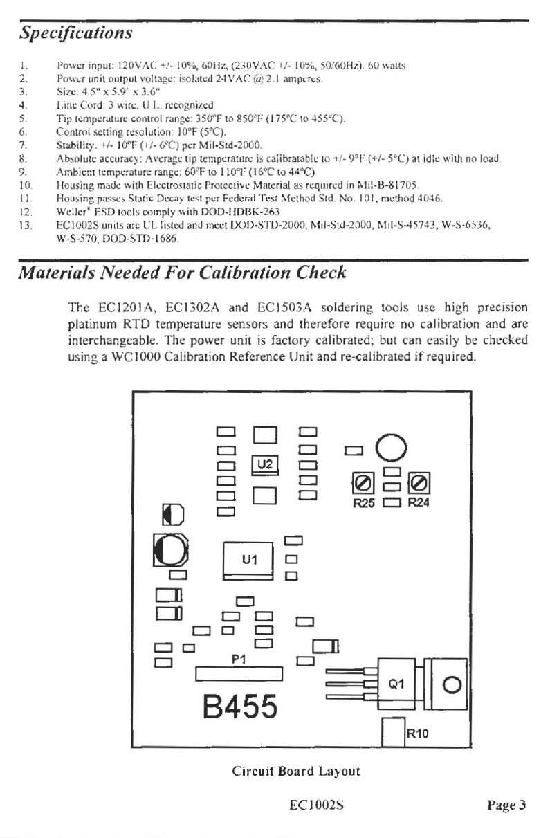
3. Adjust RI
0,
accessible through the hole
in
the station bottom directly
be
l
ow
the
temperature set knob. until the indicated tip temperature matches the
se
t
temperature.
ECJ002S Re-calibration Procedure
Because the power unit must
be
dis-assembled to gain access
to
the calibration
adjustments, this procedure is not recommended unless the Calibration Check
is
performed
and
re-calibration
is
indicated.
CAUTION: Disconnect power cord before
di
s-assembling power unit.
I. Remove 4 rubber feet
and
sc
rews under feet; remo
ve
top cover
from
station.
Page 4 ECI002S