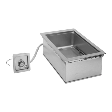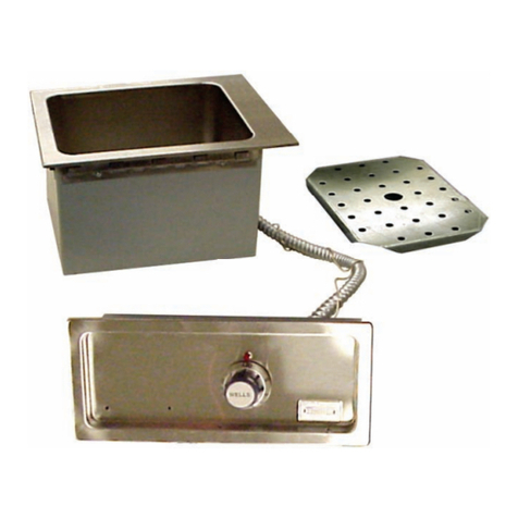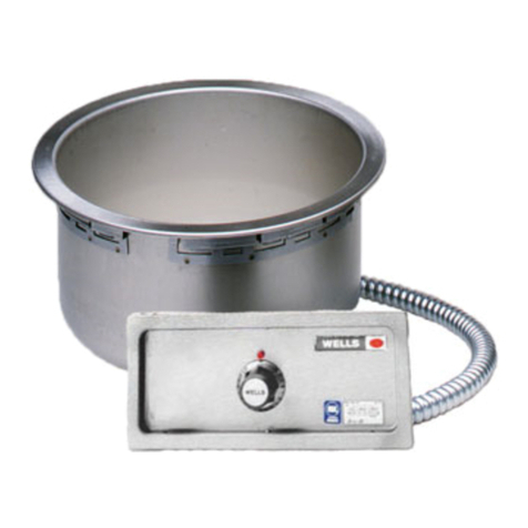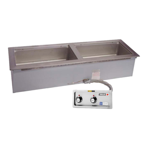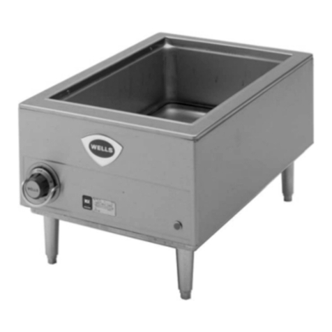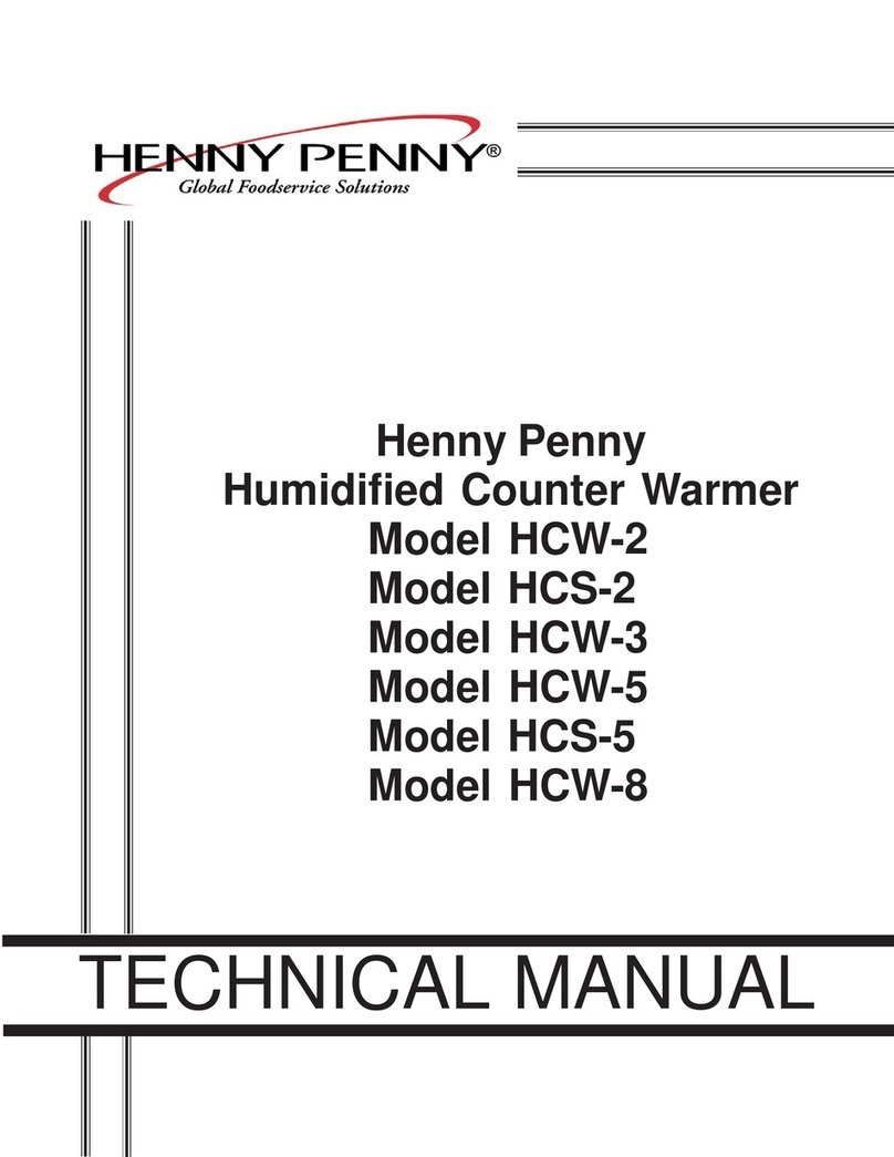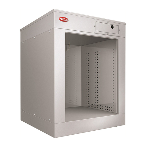
BUILT-IN MODULAR WARMERS
BUILT-IN MODULAR WARMERS
I T E M N O .
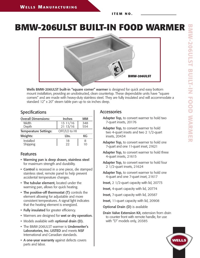
Features
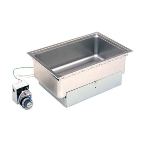
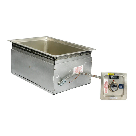
• Individual controls on each well give the warmers
maximum versatility.
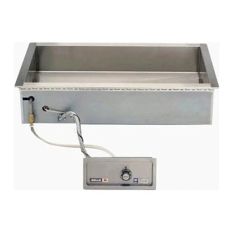
• Wellslok allows for quick and easy installation in stainless
steel countertops.
• Designed for wet or dry operation.
• Fully insulated for greater efficiency.
• Thermostat (T) models with higher wattage provide
more accurate temperature control.
• Each well is one-piece, deep-drawn, stainless steel
construction for maximum strength and durability.
• The MOD series Warmers are Underwriters
Laboratories, Inc. LISTED and meet the National
Sanitation Foundation and Canadian standards.
• A one-year warranty against defects covers
parts and labor.
Accessories / Options
Wellslok Extension Kit, designed for installation in
a variety of countertops up to 1” thick, refer to
installation instructions, 22593
Drain Valve Extension Kit, extension from drain
to counter front with remote handle, for use with
“D” models only, excluding “DM” models, 20385
Drain Screen, 21709
Optional 72” Wiring, infinite or thermostatically
controlled warmers, priced per well
Individual drain (D), for all models
Individual thermostat (T), for all models
Individual drain connected to the manifold (DM),
for all models except MOD-100
Individual thermostat and drain connected to
the manifold(TDM), for all models except MOD-100
Export
The following models are available for export and meet
the standards for CE:
• MOD-100EUT, 220-240V, 1Ø, 1650 watts
• MOD-100EUTD, 220-240V, 1Ø, 1650 watts
WE L L S M A N U F A C T U R I N G
R A I S I N G T H E S T A N D A R D
Specifications
Weights: Lbs. KG
MOD-100 series:
Installed 19 9
Shipping 21 10
MOD-200 series:
Installed 46 21
Shipping 56 25
MOD-300 series:
Installed 64 29
Shipping 78 35
MOD-400 series:
Installed 81 37
Shipping 98 44
MOD-500 series:
Installed 101 46
Shipping 122 55
WELLS MANUFACTURING COMPANY
2 ERIK CIRCLE, PO BOX 280, VERDI, NV 89439 U.S.A. • USA PHONE: (775) 345-0444 • FAX: (775) 345-0569
FOR ORDERS ONLY: (888) 356-5362 • FAX: (800) 356-5142 • www.wellsbloomfield.com
A SPECIALTY EQUIPMENT COMPANY • 2000 WELLS MANUFACTURING • PRINTED IN THE U.S.A. • 7/00 • REV(G) • PART NO. 37099
NOTE: Specifications are subject to change without notice. See installation instruction
sheet prior to installing the unit. This document is not for installation purposes.
The Drain Manifold with Valve (1" internal N.P.T.) is supplied for DM & TDM models only.
WE L L S M A N U F A C T U R I N G
Explanation of Built-In Warmer Suffixes:
D . . . . with drain
T . . . . thermostatically controlled
TD . . . . thermostatically controlled/with drain
DM . . . with drain/connected to drain manifold/
infinite control
TDM . . thermostatically controlled/with drain/
connected to drain manifold
None . . infinite control
MOD-500 208 4500 15.0 11.2 11.2 21.6 NONE
MOD-500 240 6000 17.0 13.0 13.0 25.0 NONE
MOD-500T 208 6200 19.5 14.6 14.6 29.8 NONE
MOD-500T 240 8250 22.1 16.9 16.9 34.4 NONE
MODELS
MOD-500, MOD-500D
MOD-500T, MOD-500TD
MOD-500DM, MOD-500TDM
B U I LT- I N M O D U L A R WA R M E R S
’T’ MODELS
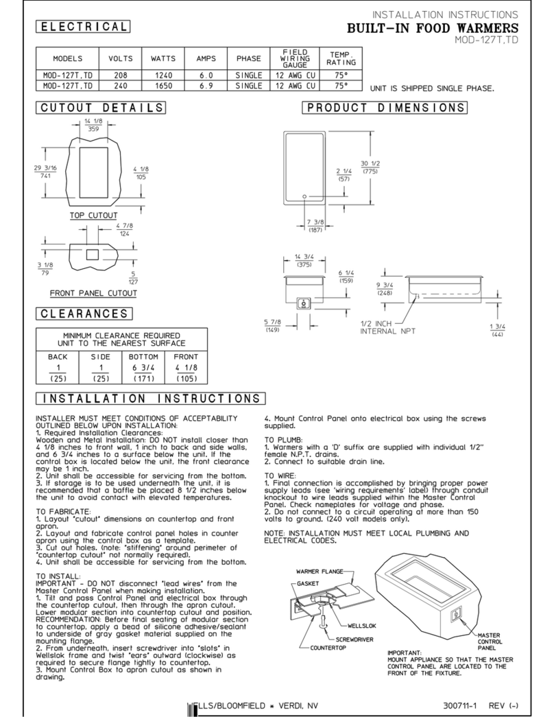
1/2 INCH
INTERNAL N.P.T.
’D’ MODELS ONLY
35
(889)
2 1/4
(57)
23 5/8
(600)
71 1/2
(1816)
18
(457)
6 1/4
(159)
9 3/4
(248)
1 3/4
(44)
7 3/4
(197)
14
(356)
MOD-500, MOD-500D, MOD-500T, MOD-500TD,
M O D - 5 0 0 D M A N D M O D - 5 0 0 T D M E L E C T R I C A L S P E C I F I C AT I O N S :
DIMENSIONS:
LISTED STD.4 E6070
E6070
INCH
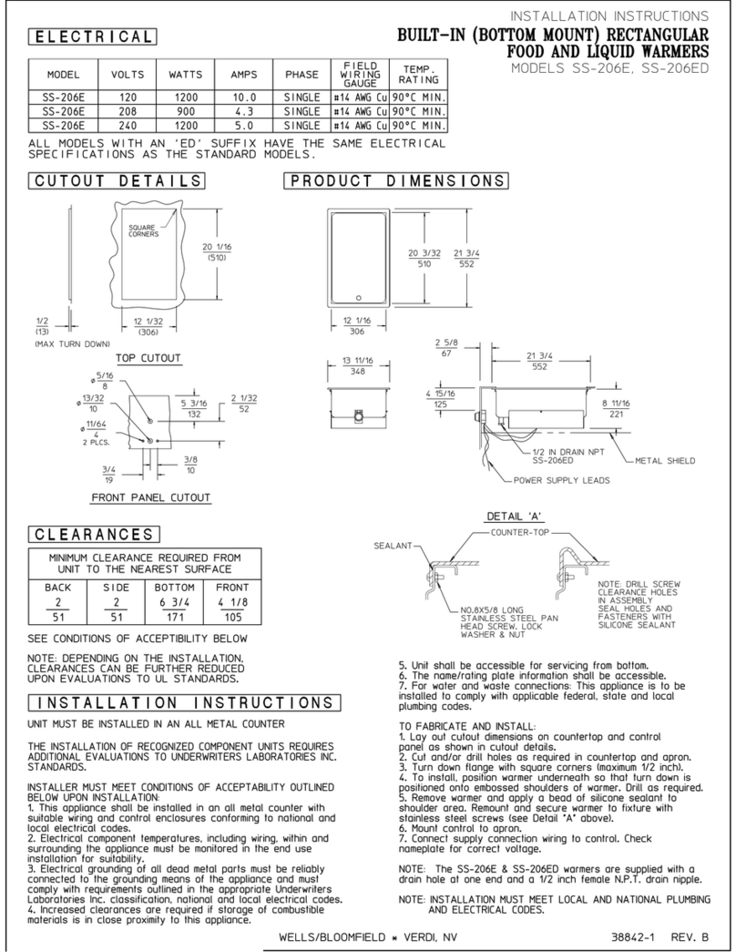
(MM) MINIMUM CLEARANCE REQUIRED FROM UNIT
TO THE NEAREST SURFACE.
BACK SIDE BOTTOM FRONT
1 1 6 3/4 6
(25) (25) (171) (152)
WELLS MANUFACTURING COMPANY
2 ERIK CIRCLE, PO BOX 280, VERDI, NV 89439 U.S.A. • USA PHONE: (775) 689-5700 • FAX: (775) 689-5972
FOR ORDERS ONLY: (888) 356-5362 • FAX: (800) 356-5142 • www.wellsbloomfield.com
A SPECIALTY EQUIPMENT COMPANY • 2000 WELLS MANUFACTURING • PRINTED IN THE U.S.A. • 7/00 • REV(G) • PART NO. 37099
NOTE: Specifications are subject to change without notice. See installation instruction
sheet prior to installing the unit. This document is not for installation purposes.
The Drain Manifold with Valve (1" internal N.P.T.) is supplied for DM & TDM models only.
WE L L S M A N U F A C T U R I N G
MOD-400 208 3600 11.2 11.2 7.5 17.3 NONE
MOD-400 240 4800 13.0 13.0 8.7 20.0 NONE
MOD-400T 208 4960 14.5 14.5 9.8 23.8 NONE
MOD-400T 240 6600 17.8 17.8 11.3 27.5 NONE
MODELS
MOD-400, MOD-400D
MOD-400T, MOD-400TD
MOD-400DM, MOD-400TDM
B U I LT- I N M O D U L A R WA R M E R S
1/2 INCH
INTERNAL N.P.T.
’D’ MODELS ONLY
’T’ MODELS
35
(889)
1 3/4
(44)
9 3/4
(248)
6 1/4
(159)
18
(457)
57 1/2
(1461)
23 5/8
(600)
2 1/4
(57)
7 3/4
(197)
14
(356)
MOD-400, MOD-400D, MOD-400T, MOD-400TD,
M O D - 4 0 0 D M A N D M O D - 4 0 0 T D M E L E C T R I C A L S P E C I F I C AT I O N S :
DIMENSIONS:
LISTED STD.4 E6070
E6070
INCH
(MM) MINIMUM CLEARANCE REQUIRED FROM UNIT
TO THE NEAREST SURFACE.
BACK SIDE BOTTOM FRONT
1 1 6 3/4 6
(25) (25) (171) (152)
All models with a ‘D' or 'DM' suffix have the same electrical specs as the standard MOD-500 or MOD-500T models.
All models with a ‘D' or 'DM' suffix have the same electrical specs as the standard MOD-400 or MOD-400T models.
MOD-200TDM
MOD-400
MODELS VOLTS WATTS AMPS PER LINE PHASE 3 AMPS POWER
SINGLE PHASE SUPPLY CORD
L1 L2 L3
MODELS VOLTS WATTS AMPS PER LINE PHASE 3 AMPS POWER
SINGLE PHASE SUPPLY CORD
L1 L2 L3


